- Table of Contents
-
- H3C Fixed Port Campus Switches Configuration Examples-6W104
- 00-Applicable hardware and software versions
- 01-Login Management Configuration Examples
- 02-RBAC Configuration Examples
- 03-Software Upgrade Examples
- 04-ISSU Configuration Examples
- 05-Software Patching Examples
- 06-Ethernet Link Aggregation Configuration Examples
- 07-Port Isolation Configuration Examples
- 08-Spanning Tree Configuration Examples
- 09-VLAN Configuration Examples
- 10-VLAN Tagging Configuration Examples
- 11-DHCP Snooping Configuration Examples
- 12-Cross-Subnet Dynamic IP Address Allocation Configuration Examples
- 13-IPv6 over IPv4 Tunneling with OSPFv3 Configuration Examples
- 14-IPv6 over IPv4 GRE Tunnel Configuration Examples
- 15-GRE with OSPF Configuration Examples
- 16-OSPF Configuration Examples
- 17-IS-IS Configuration Examples
- 18-BGP Configuration Examples
- 19-Policy-Based Routing Configuration Examples
- 20-OSPFv3 Configuration Examples
- 21-IPv6 IS-IS Configuration Examples
- 22-Routing Policy Configuration Examples
- 23-IGMP Snooping Configuration Examples
- 24-IGMP Configuration Examples
- 25-MLD Snooping Configuration Examples
- 26-IPv6 Multicast VLAN Configuration Examples
- 27-ACL Configuration Examples
- 28-Traffic Policing Configuration Examples
- 29-GTS and Rate Limiting Configuration Examples
- 30-Traffic Filtering Configuration Examples
- 31-AAA Configuration Examples
- 32-Port Security Configuration Examples
- 33-Portal Configuration Examples
- 34-SSH Configuration Examples
- 35-IP Source Guard Configuration Examples
- 36-Ethernet OAM Configuration Examples
- 37-CFD Configuration Examples
- 38-DLDP Configuration Examples
- 39-VRRP Configuration Examples
- 40-BFD Configuration Examples
- 41-NTP Configuration Examples
- 42-SNMP Configuration Examples
- 43-NQA Configuration Examples
- 44-Mirroring Configuration Examples
- 45-sFlow Configuration Examples
- 46-OpenFlow Configuration Examples
- 47-MAC Address Table Configuration Examples
- 48-Static Multicast MAC Address Entry Configuration Examples
- 49-IP Unnumbered Configuration Examples
- 50-MVRP Configuration Examples
- 51-MCE Configuration Examples
- 52-Attack Protection Configuration Examples
- 53-Smart Link Configuration Examples
- 54-RRPP Configuration Examples
- 55-BGP Route Selection Configuration Examples
- 56-IS-IS Route Summarization Configuration Examples
- 57-VXLAN Configuration Examples
- 58-DRNI Configuration Examples
- 59-IRF 3.1 Configuration Examples
- 60-PTP Configuration Examples
- 61-S-MLAG Configuration Examples
- 62-Puppet Configuration Examples
- 63-802.1X Configuration Examples
- 64-MAC Authentication Configuration Examples
- 65-ISATAP Tunnel and 6to4 Tunnel Configuration Examples
- 66-BIDIR-PIM Configuration Examples
- 67-Congestion Avoidance and Queue Scheduling Configuration Examples
- 68-Basic MPLS Configuration Examples
- 69-MPLS L3VPN Configuration Examples
- 70-MPLS OAM Configuration Examples
- 71-EVPN-DCI over an MPLS L3VPN Network Configuration Examples
- 72-DRNI and EVPN Configuration Examples
- 73-Multicast VPN Configuration Examples
- 74-MPLS TE Configuration Examples
- 75-Control Plane-Based QoS Policy Configuration Examples
- 76-Priority Mapping and Queue Scheduling Configuration Examples
- 77-ARP Attack Protection Configuration Examples
- 78-IRF Software Upgrade Configuration Examples
- 79-IRF Member Replacement Configuration Examples
- 80-Layer 3 Multicast on Multicast Source-Side DR System Configuration Examples
- 81-EVPN Multicast Configuration Examples
- Related Documents
-
| Title | Size | Download |
|---|---|---|
| 11-DHCP Snooping Configuration Examples | 111.35 KB |
Introduction
This document provides DHCP snooping configuration examples.
Prerequisites
The configuration examples in this document were created and verified in a lab environment, and all the devices were started with the factory default configuration. When you are working on a live network, make sure you understand the potential impact of every command on your network.
This document assumes that you have basic knowledge of DHCP.
Example: Configuring DHCP snooping
Network configuration
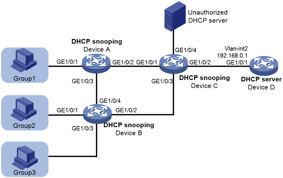
As shown in Figure 1, three groups of hosts are connected to the DHCP server through the DHCP snooping devices. Configure DHCP snooping and DHCP server to meet the following requirements:
· Hosts in each group obtain IP addresses from the address range assigned to the group. Assign address ranges to the groups as follows:
¡ Address range 192.168.0.2 to 192.168.0.39 for Group 1.
¡ Address range 192.168.0.40 to 192.168.0.99 for Group 2.
¡ Address range 192.168.0.100 to 192.168.0.200 for Group 3.
· The hosts can obtain IP addresses only from the authorized DHCP server.
· The hosts cannot access the network through IP addresses that are manually configured.
Analysis
To meet the network requirements, you must perform the following tasks:
· To make sure the hosts in each group obtain IP addresses from the address range assigned to the group, perform the following tasks:
¡ Configure Option 82 on the DHCP snooping devices.
¡ Create DHCP user classes for the groups and configure match rules based on Option 82 to match the groups on the DHCP server.
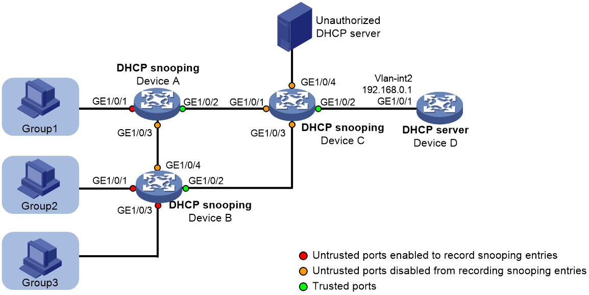
· To make sure the hosts obtain addresses only from the authorized DHCP server, configure ports facing the server as trusted and other ports as untrusted, as shown in Figure 2.
· To prevent illegal users from using manually configured IP addresses to access the network, perform the following tasks:
¡ Enable ARP detection in the VLANs where the groups reside to check user validity based on DHCP snooping entries.
¡ Enable recording of client information in DHCP snooping entries. To save system resources, you can enable only untrusted ports directly connected to hosts to record DHCP snooping entries, as shown in Figure 2.
Figure 2 Trusted and untrusted ports
Applicable hardware and software versions
The following matrix shows the hardware and software versions to which this configuration example is applicable:
|
Hardware |
Software version |
|
S6813 switch series |
Release 6615Pxx, Release 6628Pxx |
|
S6550XE-HI switch series |
Release 6008 and later, Release 8106Pxx |
|
S6525XE-HI switch series |
Release 6008 and later, Release 8106Pxx |
|
S5850 switch series |
Release 8005 and later |
|
S5570S-EI switch series |
Release 11xx |
|
S5560X-EI switch series |
Release 63xx, Release 65xx, and Release 6615Pxx, Release 6628Pxx |
|
S5560X-HI switch series |
Release 63xx, Release 65xx, and Release 6615Pxx, Release 6628Pxx |
|
S5500V2-EI switch series |
Release 63xx, Release 65xx, and Release 6615Pxx, Release 6628Pxx |
|
MS4520V2-30F switch |
Release 63xx and Release 65xx, and Release 6615Pxx, Release 6628Pxx |
|
MS4520V2-30C switch MS4520V2-54C switch |
Release 65xx and Release 6615Pxx, Release 6628Pxx |
|
MS4520V2-28S switch MS4520V2-24TP switch |
Release 63xx |
|
S6520X-HI switch series S6520X-EI switch series |
Release 63xx, Release 65xx, and Release 6615Pxx, Release 6628Pxx |
|
S6520X-SI switch series S6520-SI switch series |
Release 63xx, Release 65xx, and Release 6615Pxx, Release 6628Pxx |
|
S5000-EI switch series |
Release 63xx, Release 65xx, and Release 6615Pxx, Release 6628Pxx |
|
MS4600 switch series |
Release 63xx, Release 65xx, and Release 6615Pxx, Release 6628Pxx |
|
ES5500 switch series |
Release 63xx, Release 65xx, and Release 6615Pxx, Release 6628Pxx |
|
S5560S-EI switch series S5560S-SI switch series |
Release 63xx |
|
S5500V3-24P-SI S5500V3-48P-SI |
Release 63xx |
|
S5500V3-SI switch series (except S5500V3-24P-SI and S5500V3-48P-SI) |
Release 11xx |
|
S5170-EI switch series |
Release 11xx |
|
S5130S-HI switch series S5130S-EI switch series S5130S-SI switch series S5130S-LI switch series |
Release 63xx |
|
S5120V2-SI switch series S5120V2-LI switch series |
Release 63xx |
|
S5120V3-EI switch series |
Release 11xx |
|
S5120V3-36F-SI S5120V3-28P-HPWR-SI S5120V3-54P-PWR-SI |
Release 11xx |
|
S5120V3-SI switch series (except S5120V3-36F-SI, S5120V3-28P-HPWR-SI, and S5120V3-54P-PWR-SI) |
Release 63xx |
|
S5120V3-LI switch series |
Release 63xx |
|
S3600V3-EI switch series |
Release 11xx |
|
S3600V3-SI switch series |
Release 11xx |
|
S3100V3-EI switch series S3100V3-SI switch series |
Release 63xx |
|
S5110V2 switch series |
Release 63xx |
|
S5110V2-SI switch series |
Release 63xx |
|
S5000V3-EI switch series S5000V5-EI switch series |
Release 63xx |
|
S5000E-X switch series S5000X-EI switch series |
Release 63xx |
|
E128C switch E152C switch E500C switch series E500D switch series |
Release 63xx |
|
MS4320V2 switch series MS4320V3 switch series MS4300V2 switch series MS4320 switch series MS4200 switch series |
Release 63xx |
|
WS5850-WiNet switch series |
Release 63xx |
|
WS5820-WiNet switch series WS5810-WiNet switch series |
Release 63xx |
|
WAS6000 switch series |
Release 63xx |
|
IE4300-12P-AC switch IE4300-12P-PWR switch IE4300-M switch series IE4320 switch series |
Release 63xx |
The S5110V2-SI, S5000V3-EI, S5000V5-EI, S5000E-X, and WAS6000 switch series do not support the DHCP server.
Restrictions and guidelines
To ensure correct DHCP address allocation by using Option 82, you must perform Option 82 configuration on the DHCP server and the DHCP snooping devices.
Procedures
Configuring Device A
# Enable DHCP snooping.
<DeviceA> system-view
[DeviceA] dhcp snooping enable
# Enable recording of client information in DHCP snooping entries on interface GigabitEthernet 1/0/1.
[DeviceA] interface gigabitethernet 1/0/1
[DeviceA-GigabitEthernet1/0/1] dhcp snooping binding record
# Enable DHCP snooping to support Option 82 on GigabitEthernet 1/0/1. Configure the padding content for the Circuit ID sub-option as group1.
[DeviceA-GigabitEthernet1/0/1] dhcp snooping information enable
[DeviceA-GigabitEthernet1/0/1] dhcp snooping information circuit-id string group1
[DeviceA-GigabitEthernet1/0/1] quit
# Configure GigabitEthernet 1/0/2 as a trusted port.
[DeviceA] interface gigabitethernet 1/0/2
[DeviceA-GigabitEthernet1/0/2] dhcp snooping trust
[DeviceA-GigabitEthernet1/0/2] quit
# Enable ARP attack detection for user validity check.
[DeviceA] vlan 1
[DeviceA-vlan1] arp detection enable
[DeviceA-vlan1] quit
# Configure GigabitEthernet 1/0/2 as an ARP trusted port. By default, an interface is an ARP untrusted port.
[DeviceA] interface gigabitethernet 1/0/2
[DeviceA-GigabitEthernet1/0/2] arp detection trust
[DeviceA-GigabitEthernet1/0/2] quit
Configuring Device B
# Enable DHCP snooping.
<DeviceB> system-view
[DeviceB] dhcp snooping enable
# Enable recording of client information in DHCP snooping entries on GigabitEthernet 1/0/1.
[DeviceB] interface gigabitethernet 1/0/1
[DeviceB-GigabitEthernet1/0/1] dhcp snooping binding record
# Enable DHCP snooping to support Option 82 on interface GigabitEthernet 1/0/1. Configure the padding content for the Circuit ID sub-option as group2.
[DeviceB-GigabitEthernet1/0/1] dhcp snooping information enable
[DeviceB-GigabitEthernet1/0/1] dhcp snooping information circuit-id string group2
[DeviceB-GigabitEthernet1/0/1] quit
# Configure gigabitethernet 1/0/2 as a trusted port.
[DeviceB] interface GigabitEthernet 1/0/2
[DeviceB-GigabitEthernet1/0/2] dhcp snooping trust
[DeviceB-GigabitEthernet1/0/2] quit
# Enable recording of client information in DHCP snooping entries on GigabitEthernet 1/0/3.
[DeviceB] interface gigabitethernet 1/0/3
[DeviceB-GigabitEthernet1/0/3] dhcp snooping binding record
# Enable DHCP snooping to support Option 82 on GigabitEthernet 1/0/3. Configure the padding content for the Circuit ID sub-option as group3.
[DeviceB-GigabitEthernet1/0/3] dhcp snooping information enable
[DeviceB-GigabitEthernet1/0/3] dhcp snooping information circuit-id string group3
[DeviceB-GigabitEthernet1/0/3] quit
# Enable ARP attack detection for user validity check.
[DeviceB] vlan 1
[DeviceB-vlan1] arp detection enable
[DeviceB-vlan1] quit
# Configure GigabitEthernet 1/0/2 as an ARP trusted port. By default, an interface is an ARP untrusted port.
[DeviceB] interface gigabitethernet 1/0/2
[DeviceB-GigabitEthernet1/0/2] arp detection trust
[DeviceB-GigabitEthernet1/0/2] quit
Configuring Device C
# Enable DHCP snooping.
<DeviceC> system-view
[DeviceC] dhcp snooping enable
# Configure GigabitEthernet 1/0/2 as a trusted port.
[DeviceC] interface gigabitethernet 1/0/2
[DeviceC-GigabitEthernet1/0/2] dhcp snooping trust
[DeviceC-GigabitEthernet1/0/2] quit
Configuring Device D
# Assign GigabitEthernet 1/0/1 to VLAN 2.
<DeviceD> system-view
[DeviceD] vlan 2
[DeviceD-vlan2] port gigabitethernet 1/0/1
[DeviceD-vlan2] quit
# Assign an IP address to VLAN-interface 2.
[DeviceD] interface vlan-interface 2
[DeviceD-Vlan-interface2] ip address 192.168.0.1 24
[DeviceD-Vlan-interface2] quit
# Enable DHCP.
[DeviceD] dhcp enable
# Enable DHCP server on VLAN-interface 2.
[DeviceD] interface vlan-interface 2
[DeviceD-Vlan-interface2] dhcp select server
[DeviceD-Vlan-interface2] quit
# Create DHCP user class group1 for hosts in Group 1. Configure a match rule to match DHCP requests in which the third to eighth bytes of Option 82 is 0x67726F757031. The string 0x67726F757031 indicates that the content of the Circuit ID sub-option is group1.
[DeviceD] dhcp class group1
[DeviceD-dhcp-class-group1] if-match option 82 hex 67726F757031 offset 2 length 6
[DeviceD-dhcp-class-group1] quit
# Create DHCP user class group2 for hosts in Group 2. Configure a match rule to match DHCP requests in which the third to eighth bytes of Option 82 is 0x67726F757032. The string 0x67726F757032 indicates that the content of the Circuit ID sub-option is group2.
[DeviceD] dhcp class group2
[DeviceD-dhcp-class-group2] if-match option 82 hex 67726F757032 offset 2 length 6
[DeviceD-dhcp-class-group2] quit
# Create DHCP user class group3 for hosts in Group 3. Configure a match rule to match DHCP requests in which the third to eighth bytes of Option 82 is 0x67726F757033. The string 0x67726F757033 indicates that the content of the Circuit ID sub-option is group3.
[DeviceD] dhcp class group3
[DeviceD-dhcp-class-group3] if-match option 82 hex 67726F757033 offset 2 length 6
[DeviceD-dhcp-class-group3] quit
# Create a DHCP address pool.
[DeviceD] dhcp server ip-pool 1
# Specify the subnet for dynamic address allocation.
[DeviceD-dhcp-pool-1] network 192.168.0.0 mask 255.255.255.0
# Specify address range 192.168.0.2 to 192.168.0.39 for DHCP user class group1.
[DeviceD-dhcp-pool-1] class group1 range 192.168.0.2 192.168.0.39
# Specify address range 192.168.0.40 to 192.168.0.99 for DHCP user class group2.
[DeviceD-dhcp-pool-1] class group2 range 192.168.0.40 192.168.0.99
# Specify address range 192.168.0.100 to 192.168.0.200 for DHCP user class group3.
[DeviceD-dhcp-pool-1] class group3 range 192.168.0.100 192.168.0.200
# Apply the DHCP address pool to VLAN-interface 2.
[DeviceD] interface vlan-interface 2
[DeviceD-Vlan-interface2] dhcp server apply ip-pool 1
[DeviceD-Vlan-interface2] quit
Verifying the configuration
# Verify that the hosts in each group can obtain IP addresses from the address range assigned to the group. This example uses a host in Group 2 to verify the configuration.
C:\Documents and Settings\Administrator>ipconfig
Windows IP Configuration
Ethernet adapter bb:
Connection-specific DNS Suffix . :
IP Address. . . . . . . . . . . . : 192.168.0.44
Subnet Mask . . . . . . . . . . . : 255.255.255.0
Default Gateway . . . . . . . . . :
# Manually assign IP address 192.168.0.66 to a host in Group 2, and verify that it cannot access the external network. (Details not shown.)
Configuration files
|
|
IMPORTANT: Support for the port link-mode bridge command depends on the device model. |
· Device A:
#
dhcp snooping enable
#
vlan 1
arp detection enable
#
interface GigabitEthernet1/0/1
dhcp snooping binding record
dhcp snooping information enable
dhcp snooping information circuit-id string group1
#
interface GigabitEthernet1/0/2
arp detection trust
dhcp snooping trust
#
· Device B:
#
dhcp snooping enable
#
vlan 1
arp detection enable
#
interface GigabitEthernet1/0/1
dhcp snooping binding record
dhcp snooping information enable
dhcp snooping information circuit-id string group2
#
interface GigabitEthernet1/0/2
arp detection trust
dhcp snooping trust
#
interface GigabitEthernet1/0/3
dhcp snooping binding record
dhcp snooping information enable
dhcp snooping information circuit-id string group3
#
· Device C:
#
dhcp snooping enable
#
interface GigabitEthernet1/0/2
dhcp snooping trust
#
· Device D:
#
dhcp enable
#
vlan 2
#
dhcp class group1
if-match option 82 hex 67726f757031 offset 2 length 6
#
dhcp class group2
if-match option 82 hex 67726f757032 offset 2 length 6
#
dhcp class group3
if-match option 82 hex 67726f757033 offset 2 length 6
#
dhcp server ip-pool 1
network 192.168.0.0 mask 255.255.255.0
class group1 range 192.168.0.2 192.168.0.39
class group2 range 192.168.0.40 192.168.0.99
class group3 range 192.168.0.100 192.168.0.200
#
interface Vlan-interface2
ip address 192.168.0.1 255.255.255.0
dhcp server apply ip-pool 1
