- Table of Contents
-
- H3C Fixed Port Campus Switches Configuration Examples-6W104
- 00-Applicable hardware and software versions
- 01-Login Management Configuration Examples
- 02-RBAC Configuration Examples
- 03-Software Upgrade Examples
- 04-ISSU Configuration Examples
- 05-Software Patching Examples
- 06-Ethernet Link Aggregation Configuration Examples
- 07-Port Isolation Configuration Examples
- 08-Spanning Tree Configuration Examples
- 09-VLAN Configuration Examples
- 10-VLAN Tagging Configuration Examples
- 11-DHCP Snooping Configuration Examples
- 12-Cross-Subnet Dynamic IP Address Allocation Configuration Examples
- 13-IPv6 over IPv4 Tunneling with OSPFv3 Configuration Examples
- 14-IPv6 over IPv4 GRE Tunnel Configuration Examples
- 15-GRE with OSPF Configuration Examples
- 16-OSPF Configuration Examples
- 17-IS-IS Configuration Examples
- 18-BGP Configuration Examples
- 19-Policy-Based Routing Configuration Examples
- 20-OSPFv3 Configuration Examples
- 21-IPv6 IS-IS Configuration Examples
- 22-Routing Policy Configuration Examples
- 23-IGMP Snooping Configuration Examples
- 24-IGMP Configuration Examples
- 25-MLD Snooping Configuration Examples
- 26-IPv6 Multicast VLAN Configuration Examples
- 27-ACL Configuration Examples
- 28-Traffic Policing Configuration Examples
- 29-GTS and Rate Limiting Configuration Examples
- 30-Traffic Filtering Configuration Examples
- 31-AAA Configuration Examples
- 32-Port Security Configuration Examples
- 33-Portal Configuration Examples
- 34-SSH Configuration Examples
- 35-IP Source Guard Configuration Examples
- 36-Ethernet OAM Configuration Examples
- 37-CFD Configuration Examples
- 38-DLDP Configuration Examples
- 39-VRRP Configuration Examples
- 40-BFD Configuration Examples
- 41-NTP Configuration Examples
- 42-SNMP Configuration Examples
- 43-NQA Configuration Examples
- 44-Mirroring Configuration Examples
- 45-sFlow Configuration Examples
- 46-OpenFlow Configuration Examples
- 47-MAC Address Table Configuration Examples
- 48-Static Multicast MAC Address Entry Configuration Examples
- 49-IP Unnumbered Configuration Examples
- 50-MVRP Configuration Examples
- 51-MCE Configuration Examples
- 52-Attack Protection Configuration Examples
- 53-Smart Link Configuration Examples
- 54-RRPP Configuration Examples
- 55-BGP Route Selection Configuration Examples
- 56-IS-IS Route Summarization Configuration Examples
- 57-VXLAN Configuration Examples
- 58-DRNI Configuration Examples
- 59-IRF 3.1 Configuration Examples
- 60-PTP Configuration Examples
- 61-S-MLAG Configuration Examples
- 62-Puppet Configuration Examples
- 63-802.1X Configuration Examples
- 64-MAC Authentication Configuration Examples
- 65-ISATAP Tunnel and 6to4 Tunnel Configuration Examples
- 66-BIDIR-PIM Configuration Examples
- 67-Congestion Avoidance and Queue Scheduling Configuration Examples
- 68-Basic MPLS Configuration Examples
- 69-MPLS L3VPN Configuration Examples
- 70-MPLS OAM Configuration Examples
- 71-EVPN-DCI over an MPLS L3VPN Network Configuration Examples
- 72-DRNI and EVPN Configuration Examples
- 73-Multicast VPN Configuration Examples
- 74-MPLS TE Configuration Examples
- 75-Control Plane-Based QoS Policy Configuration Examples
- 76-Priority Mapping and Queue Scheduling Configuration Examples
- 77-ARP Attack Protection Configuration Examples
- 78-IRF Software Upgrade Configuration Examples
- 79-IRF Member Replacement Configuration Examples
- 80-Layer 3 Multicast on Multicast Source-Side DR System Configuration Examples
- 81-EVPN Multicast Configuration Examples
- Related Documents
-
| Title | Size | Download |
|---|---|---|
| 30-Traffic Filtering Configuration Examples | 102.29 KB |
Introduction
This document provides traffic filtering configuration examples.
Prerequisites
The configuration examples in this document were created and verified in a lab environment, and all the devices were started with the factory default configuration. When you are working on a live network, make sure you understand the potential impact of every command on your network.
This document assumes that you have basic knowledge of traffic filtering.
Example: Configuring traffic filtering
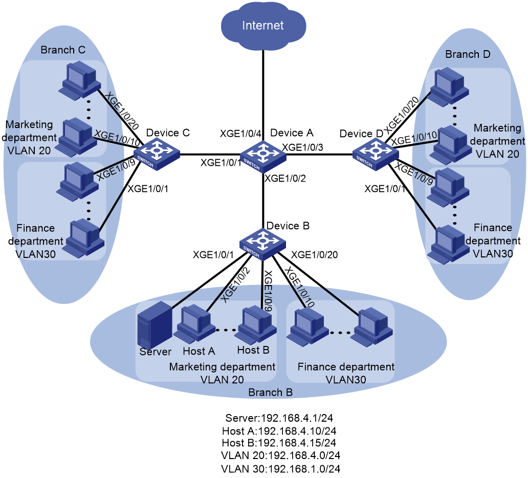
Network configuration
As shown in Figure 1, a company has three branches, each of which has a Marketing department and a Finance department. All Marketing departments belong to VLAN 20. All Finance departments belong to VLAN 30.
Configure traffic filtering to meet the following requirements:
· HTTP traffic from the Marketing department in each branch is denied.
· In Branch B, only Host A and Host B can access the server.
· The Marketing departments in three branches can access one another, and the Finance departments in three branches can access one another.
Analysis
To meet the network requirements, you must perform the following tasks:
· To deny HTTP traffic from the Marketing departments, use one of the following methods:
¡ Filter outgoing traffic from the subnet 192.168.4.0/24 on the interfaces that connect Device B, Device C, and Device D to Device A.
This method has poor scalability, because new branches require the same configuration on their access switches.
¡ Filter outgoing traffic from the subnet 192.168.4.0/24 on interface GigabitEthernet 1/0/4 of Device A.
This method wastes processing capabilities of Device A, because Device A must internally forward all incoming traffic to interface GigabitEthernet 1/0/4.
¡ Configure a QoS policy to deny HTTP traffic from the Marketing departments.
This method can automatically adapt to changing network topologies and also saves hardware resources by denying traffic on the incoming interface. This example uses this method.
· To allow only Host A and Host B to access the server in Branch B, perform the following tasks:
¡ Configure an ACL on GigabitEthernet 1/0/1 to allow packets from 192.168.4.10/24 and 192.168.4.15/24.
¡ Set the default packet filtering action to deny to deny packets that do not match the configured ACL.
· To allow traffic from Marketing departments and Finance departments (except HTTP traffic) to the Internet and to allow access among Marketing departments and among Finance departments, perform the following tasks:
¡ Configure GigabitEthernet 1/0/1 through GigabitEthernet 1/0/4 as trunk ports.
¡ Assign these interfaces to VLAN 20 and VLAN 30.
Applicable hardware and software versions
The following matrix shows the hardware and software versions to which this configuration example is applicable:
|
Hardware |
Software version |
|
S6812 switch series S6813 switch series |
Release 6615Pxx, Release 6628Pxx |
|
S6550XE-HI switch series |
Release 6008 and later, Release 8106Pxx |
|
S6525XE-HI switch series |
Release 6008 and later, Release 8106Pxx |
|
S5850 switch series |
Release 8005 and later |
|
S5570S-EI switch series |
Release 11xx |
|
S5560X-EI switch series |
Release 63xx, Release 65xx, Release 6615Pxx, Release 6628Pxx |
|
S5560X-HI switch series |
Release 63xx, Release 65xx, Release 6615Pxx, Release 6628Pxx |
|
S5500V2-EI switch series |
Release 63xx, Release 65xx, Release 6615Pxx, Release 6628Pxx |
|
MS4520V2-30F switch |
Release 63xx, Release 65xx, Release 6615Pxx, Release 6628Pxx |
|
MS4520V2-30C switch MS4520V2-54C switch |
Release 65xx, Release 6615Pxx, Release 6628Pxx |
|
MS4520V2-28S switch MS4520V2-24TP switch |
Release 63xx |
|
S6520X-HI switch series S6520X-EI switch series |
Release 63xx, Release 65xx, Release 6615Pxx, Release 6628Pxx |
|
S6520X-SI switch series S6520-SI switch series |
Release 63xx, Release 65xx, Release 6615Pxx, Release 6628Pxx |
|
S5000-EI switch series |
Release 63xx, Release 65xx, Release 6615Pxx, Release 6628Pxx |
|
MS4600 switch series |
Release 63xx, Release 65xx, Release 6615Pxx, Release 6628Pxx |
|
ES5500 switch series |
Release 63xx, Release 65xx, Release 6615Pxx, Release 6628Pxx |
|
S5560S-EI switch series S5560S-SI switch series |
Release 63xx |
|
S5500V3-24P-SI S5500V3-48P-SI |
Release 63xx |
|
S5500V3-SI switch series (except S5500V3-24P-SI and S5500V3-48P-SI) |
Release 11xx |
|
S5170-EI switch series |
Release 11xx |
|
S5130S-HI switch series S5130S-EI switch series S5130S-SI switch series S5130S-LI switch series |
Release 63xx |
|
S5120V2-SI switch series S5120V2-LI switch series |
Release 63xx |
|
S5120V3-EI switch series |
Release 11xx |
|
S5120V3-36F-SI S5120V3-28P-HPWR-SI S5120V3-54P-PWR-SI |
Release 11xx |
|
S5120V3-SI switch series (except S5120V3-36F-SI, S5120V3-28P-HPWR-SI, and S5120V3-54P-PWR-SI) |
Release 63xx |
|
S5120V3-LI switch series |
Release 63xx |
|
S3600V3-EI switch series |
Release 11xx |
|
S3600V3-SI switch series |
Release 11xx |
|
S3100V3-EI switch series S3100V3-SI switch series |
Release 63xx |
|
S5110V2 switch series |
Release 63xx |
|
S5110V2-SI switch series |
Release 63xx |
|
S5000V3-EI switch series S5000V5-EI switch series |
Release 63xx |
|
S5000E-X switch series S5000X-EI switch series |
Release 63xx |
|
E128C switch E152C switch E500C switch series E500D switch series |
Release 63xx |
|
MS4320V2 switch series MS4320V3 switch series MS4300V2 switch series MS4320 switch series MS4200 switch series |
Release 63xx |
|
WS5850-WiNet switch series |
Release 63xx |
|
WS5820-WiNet switch series WS5810-WiNet switch series |
Release 63xx |
|
WAS6000 switch series |
Release 63xx |
|
IE4300-12P-AC switch IE4300-12P-PWR switch IE4300-M switch series IE4320 switch series |
Release 63xx |
The port link-mode command is not supported on the following switches and the port link-mode bridge command does not appear in their configuration files.
· S5130S-HI series.
· S5130S-EI series.
· S3100V3-EI series.
· E128C switch.
· E152C switch.
· E500C series.
· E500D series.
· IE4300-12P-AC switch
· IE4300-12P-PWR switch.
· IE4300-M series.
· IE4320 series.
Restrictions and guidelines
If a traffic behavior is configured with the filter deny action, all other actions in the same QoS policy except traffic accounting do not take effect.
Procedures
Configuring Device A
# Create VLAN 20 and VLAN 30.
<DeviceA> system-view
[DeviceA] vlan 20
[DeviceA-vlan20] quit
[DeviceA] vlan 30
[DeviceA-vlan30] quit
# Add GigabitEthernet 1/0/1 through GigabitEthernet 1/0/4 to interface range named myport.
[DeviceA] interface range name myport interface gigabitethernet 1/0/1 to gigabitethernet 1/0/4
# Configures interfaces GigabitEthernet 1/0/1 through GigabitEthernet 1/0/4 as trunk ports, assign them to VLAN 20 and VLAN 30, and remove them from VLAN 1.
[DeviceA-if-range-myport] port link-type trunk
[DeviceA-if-range-myport] port trunk permit vlan 20 30
[DeviceA-if-range-myport] undo port trunk permit vlan 1
[DeviceA-if-range-myport] quit
# Configure advanced IPv4 ACL 3000 to match HTTP traffic from subnet 192.168.4.0/24.
[DeviceA] acl advanced 3000
[DeviceA-acl-ipv4-adv-3000] rule deny tcp source 192.168.4.0 0.0.0.255 source-port eq 80
[DeviceA-acl-ipv4-adv-3000] quit
# Create a class named vlan20_http, and use ACL 3000 as the match criterion.
[DeviceA] traffic classifier vlan20_http
[DeviceA-classifier-vlan20_http] if-match acl 3000
[DeviceA-classifier-vlan20_http] quit
# Create a behavior named vlan20_http, and configure traffic filtering to deny traffic of the class vlan20_http.
[DeviceA] traffic behavior vlan20_http
[DeviceA-behavior-vlan20_http] filter deny
[DeviceA-behavior-vlan20_http] quit
# Create a QoS policy named vlan20_http, and associate the class vlan20_http with the behavior vlan20_http in the QoS policy.
[DeviceA] qos policy vlan20_http
[DeviceA-qospolicy-vlan20_http] classifier vlan20_http behavior vlan20_http
[DeviceA-qospolicy-vlan20_http] quit
# Apply the QoS policy vlan20_http to the inbound direction of VLAN 20 and VLAN 30.
[DeviceA] qos vlan-policy vlan20_http vlan 20 30 inbound
Configuring Device B
# Configure basic IPv4 ACL 2000 to permit traffic from Host A and Host B.
[DeviceB] acl basic 2000
[DeviceB-acl-ipv4-basic-2000] rule permit source 192.168.4.10 0
[DeviceB-acl-ipv4-basic-2000] rule permit source 192.168.4.15 0
[DeviceB-acl-ipv4-basic-2000] quit
# Set the packet filtering default action to deny.
[DeviceB] packet-filter default deny
# Apply ACL 2000 to interface GigabitEthernet 1/0/1 to filter outgoing traffic.
[DeviceB] interface gigabitethernet 1/0/1
[DeviceB-GigabitEthernet1/0/1] packet-filter 2000 outbound
Verifying the configuration
# Verify the QoS policy applied to the inbound direction of VLAN 20 and VLAN 30.
[DeviceA]display qos vlan-policy vlan inbound
Direction: Inbound
Policy: vlan20_http
Classifier: vlan20_http
Operator: AND
Rule(s) :
If-match acl 3000
Behavior: vlan20_http
Filter enable: Deny
Vlan 30
Direction: Inbound
Policy: vlan20_http
Classifier: vlan20_http
Operator: AND
Rule(s) :
If-match acl 3000
Behavior: vlan20_http
Filter enable: Deny
# Display application details of ACLs for incoming packet filtering on GigabitEthernet 1/0/1.
[DeviceB] display packet-filter verbose interface gigabitethernet 1/0/1 outbound
Interface: GigabitEthernet1/0/1
Outbound policy:
IPv4 ACL 2000
rule 0 permit source 192.168.4.10 0
IPv4 default action: Deny
Configuration files
· Device A:
#
vlan 20
#
vlan 30
#
interface range name myport interface GigabitEthernet1/0/1 to GigabitEthernet1/0/4
#
acl advanced 3000
rule 0 deny tcp source 192.168.4.0 0.0.0.255 source-port eq www
#
traffic classifier vlan20_http operator and
if-match acl 3000
#
traffic behavior vlan20_http
filter deny
#
qos policy vlan20_http
classifier vlan20_http behavior vlan20_http
#
qos vlan-policy vlan20_http vlan 20 inbound
qos vlan-policy vlan20_http vlan 30 inbound
#
interface GigabitEthernet1/0/1
port link-mode bridge
port link-type trunk
undo port trunk permit vlan 1
port trunk permit vlan 20 30
#
interface GigabitEthernet1/0/2
port link-mode bridge
port link-type trunk
undo port trunk permit vlan 1
port trunk permit vlan 20 30
#
interface GigabitEthernet1/0/3
port link-mode bridge
port link-type trunk
undo port trunk permit vlan 1
port trunk permit vlan 20 30
#
interface GigabitEthernet1/0/4
port link-mode bridge
port link-type trunk
undo port trunk permit vlan 1
port trunk permit vlan 20 30
· Device B:
#
acl basic 2000
rule 0 permit source 192.168.4.10 0
#
packet-filter default deny
#
interface GigabitEthernet1/0/1
port link-mode bridge
packet-filter 2000 outbound
#
