- Table of Contents
-
- H3C Fixed Port Campus Switches Configuration Examples-6W104
- 00-Applicable hardware and software versions
- 01-Login Management Configuration Examples
- 02-RBAC Configuration Examples
- 03-Software Upgrade Examples
- 04-ISSU Configuration Examples
- 05-Software Patching Examples
- 06-Ethernet Link Aggregation Configuration Examples
- 07-Port Isolation Configuration Examples
- 08-Spanning Tree Configuration Examples
- 09-VLAN Configuration Examples
- 10-VLAN Tagging Configuration Examples
- 11-DHCP Snooping Configuration Examples
- 12-Cross-Subnet Dynamic IP Address Allocation Configuration Examples
- 13-IPv6 over IPv4 Tunneling with OSPFv3 Configuration Examples
- 14-IPv6 over IPv4 GRE Tunnel Configuration Examples
- 15-GRE with OSPF Configuration Examples
- 16-OSPF Configuration Examples
- 17-IS-IS Configuration Examples
- 18-BGP Configuration Examples
- 19-Policy-Based Routing Configuration Examples
- 20-OSPFv3 Configuration Examples
- 21-IPv6 IS-IS Configuration Examples
- 22-Routing Policy Configuration Examples
- 23-IGMP Snooping Configuration Examples
- 24-IGMP Configuration Examples
- 25-MLD Snooping Configuration Examples
- 26-IPv6 Multicast VLAN Configuration Examples
- 27-ACL Configuration Examples
- 28-Traffic Policing Configuration Examples
- 29-GTS and Rate Limiting Configuration Examples
- 30-Traffic Filtering Configuration Examples
- 31-AAA Configuration Examples
- 32-Port Security Configuration Examples
- 33-Portal Configuration Examples
- 34-SSH Configuration Examples
- 35-IP Source Guard Configuration Examples
- 36-Ethernet OAM Configuration Examples
- 37-CFD Configuration Examples
- 38-DLDP Configuration Examples
- 39-VRRP Configuration Examples
- 40-BFD Configuration Examples
- 41-NTP Configuration Examples
- 42-SNMP Configuration Examples
- 43-NQA Configuration Examples
- 44-Mirroring Configuration Examples
- 45-sFlow Configuration Examples
- 46-OpenFlow Configuration Examples
- 47-MAC Address Table Configuration Examples
- 48-Static Multicast MAC Address Entry Configuration Examples
- 49-IP Unnumbered Configuration Examples
- 50-MVRP Configuration Examples
- 51-MCE Configuration Examples
- 52-Attack Protection Configuration Examples
- 53-Smart Link Configuration Examples
- 54-RRPP Configuration Examples
- 55-BGP Route Selection Configuration Examples
- 56-IS-IS Route Summarization Configuration Examples
- 57-VXLAN Configuration Examples
- 58-DRNI Configuration Examples
- 59-IRF 3.1 Configuration Examples
- 60-PTP Configuration Examples
- 61-S-MLAG Configuration Examples
- 62-Puppet Configuration Examples
- 63-802.1X Configuration Examples
- 64-MAC Authentication Configuration Examples
- 65-ISATAP Tunnel and 6to4 Tunnel Configuration Examples
- 66-BIDIR-PIM Configuration Examples
- 67-Congestion Avoidance and Queue Scheduling Configuration Examples
- 68-Basic MPLS Configuration Examples
- 69-MPLS L3VPN Configuration Examples
- 70-MPLS OAM Configuration Examples
- 71-EVPN-DCI over an MPLS L3VPN Network Configuration Examples
- 72-DRNI and EVPN Configuration Examples
- 73-Multicast VPN Configuration Examples
- 74-MPLS TE Configuration Examples
- 75-Control Plane-Based QoS Policy Configuration Examples
- 76-Priority Mapping and Queue Scheduling Configuration Examples
- 77-ARP Attack Protection Configuration Examples
- 78-IRF Software Upgrade Configuration Examples
- 79-IRF Member Replacement Configuration Examples
- 80-Layer 3 Multicast on Multicast Source-Side DR System Configuration Examples
- 81-EVPN Multicast Configuration Examples
- Related Documents
-
| Title | Size | Download |
|---|---|---|
| 49-IP Unnumbered Configuration Examples | 82.77 KB |
Introduction
This document provides IP unnumbered configuration examples.
This feature enables an interface to borrow an IP address from another interface on the device when the borrowing interface does not have any IP addresses. The borrowing interface is called IP unnumbered interface.
Prerequisites
The configuration examples in this document were created and verified in a lab environment, and all the devices were started with the factory default configuration. When you are working on a live network, make sure you understand the potential impact of every command on your network.
This document assumes that you have basic knowledge of IP unnumbered.
Restrictions and guidelines
When you configure IP unnumbered, follow these restrictions and guidelines:
· Loopback interfaces cannot borrow IP addresses of other interfaces.
· An interface cannot borrow an IP address from an unnumbered interface.
Example: Configuring IP unnumbered
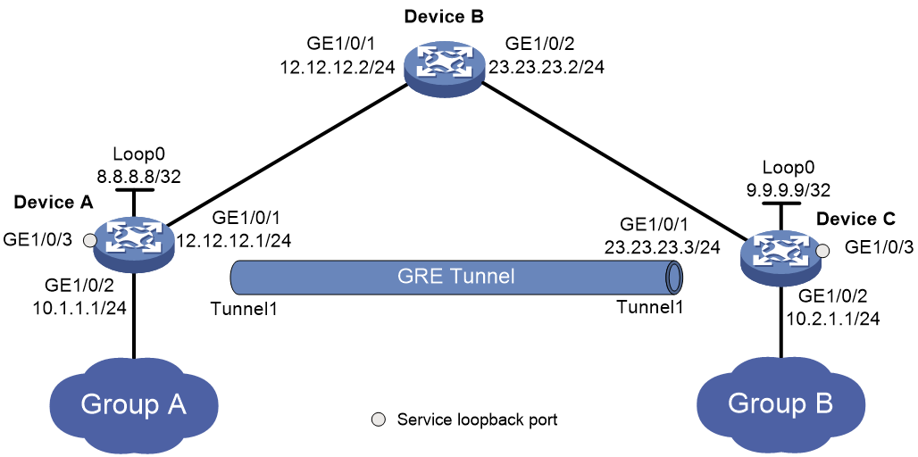
Network configuration
As shown in Figure 1, Group A and Group B are two private IPv4 networks. Device A and Device C will establish a GRE tunnel to interconnect Group 1 and Group 2.
To save IP address space, configure tunnel interface Tunnel 1 to borrow an IP address from the loopback interface loopback 0.
Applicable hardware and software versions
The following matrix shows the hardware and software versions to which this configuration example is applicable:
|
Hardware |
Software version |
|
S6812 switch series S6813 switch series |
Release 6615Pxx, Release 6628Pxx |
|
S6550XE-HI switch series |
Release 6008 and later, Release 8106Pxx |
|
S6525XE-HI switch series |
Release 6008 and later, Release 8106Pxx |
|
S5850 switch series |
Release 8005 and later |
|
S5570S-EI switch series |
Not supported |
|
S5560X-EI switch series |
Release 63xx and Release 65xx, Release 6615Pxx, Release 6628Pxx |
|
S5560X-HI switch series |
Release 63xx and Release 65xx, Release 6615Pxx, Release 6628Pxx |
|
S5500V2-EI switch series |
Release 63xx and Release 65xx, Release 6615Pxx, Release 6628Pxx |
|
MS4520V2-30F switch |
Release 63xx and Release 65xx, Release 6615Pxx, Release 6628Pxx |
|
MS4520V2-30C switch MS4520V2-54C switch |
Release 65xx, Release 6615Pxx, Release 6628Pxx |
|
MS4520V2-28S switch MS4520V2-24TP switch |
Release 63xx |
|
S6520X-HI switch series S6520X-EI switch series |
Release 63xx and Release 65xx, Release 6615Pxx, Release 6628Pxx |
|
S6520X-SI switch series S6520-SI switch series |
Release 63xx and Release 65xx, Release 6615Pxx, Release 6628Pxx |
|
S5000-EI switch series |
Release 63xx and Release 65xx, Release 6615Pxx, Release 6628Pxx |
|
MS4600 switch series |
Release 63xx and Release 65xx, Release 6615Pxx, Release 6628Pxx |
|
ES5500 switch series |
Release 63xx and Release 65xx, Release 6615Pxx, Release 6628Pxx |
|
S5560S-EI switch series S5560S-SI switch series |
Release 63xx |
|
S5500V3-24P-SI switch S5500V3-48P-SI switch |
Release 63xx |
|
S5500V3-SI switch series (except the S5500V3-24P-SI and S5500V3-48P-SI switches) |
Not supported |
|
S5170-EI switch series |
Not supported |
|
S5130S-HI switch series S5130S-EI switch series S5130S-SI switch series S5130S-LI switch series |
GRE tunneling not supported |
|
S5120V2-SI switch series S5120V2-LI switch series |
GRE tunneling not supported |
|
S5120V3-EI switch series |
Not supported |
|
S5120V3-36F-SI switch S5120V3-28P-HPWR-SI switch S5120V3-54P-PWR-SI switch |
Not supported |
|
S5120V3-SI switch series (except the S5120V3-36F-SI, S5120V3-28P-HPWR-SI, and S5120V3-54P-PWR-SI switches) |
GRE tunneling not supported |
|
S5120V3-LI switch series |
GRE tunneling not supported |
|
S3600V3-EI switch series |
Not supported |
|
S3600V3-SI switch series |
Not supported |
|
S3100V3-EI switch series S3100V3-SI switch series |
GRE tunneling not supported |
|
S5110V2 switch series |
GRE tunneling not supported |
|
S5110V2-SI switch series |
GRE tunneling not supported |
|
S5000V3-EI switch series S5000V5-EI switch series |
GRE tunneling not supported |
|
S5000E-X switch series S5000X-EI switch series |
GRE tunneling not supported |
|
E128C switch E152C switch E500C switch series E500D switch series |
GRE tunneling not supported |
|
MS4320V2 switch series MS4320V3 switch series MS4300V2 switch series MS4320 switch series MS4200 switch series |
GRE tunneling not supported |
|
WS5850-WiNet switch series |
Release 63xx |
|
WS5820-WiNet switch series WS5810-WiNet switch series |
GRE tunneling not supported |
|
WAS6000 switch series |
GRE tunneling not supported |
|
IE4300-12P-AC switch IE4300-12P-PWR switch IE4300-M switch series IE4320 switch series |
GRE tunneling not supported |
Procedures
Configuring Device A
1. Assign IP addresses to the interfaces:
# Assign IP addresses to GigabitEthernet 1/0/1 and loopback 0.
<DeviceA> system-view
[DeviceA] interface gigabitethernet 1/0/1
[DeviceA-GigabitEthernet1/0/1] port link-mode route
[DeviceA-GigabitEthernet1/0/1] ip address 12.12.12.1 24
[DeviceA-GigabitEthernet1/0/1] quit
[DeviceA] interface loopback 0
[DeviceA-LoopBack0] ip address 8.8.8.8 32
[DeviceA-LoopBack0] quit
# Assign IP addresses to other interfaces in the same way an IP address is assigned to GigabitEthernet 1/0/1. (Details not shown.)
2. Configure OSPF:
[DeviceA] ospf 1
# Create Area 0 and specify GigabitEthernet 1/0/1 whose IP address is on network 12.12.12.0/24 to run OSPF in Area 0.
[DeviceA-ospf-1] area 0
[DeviceA-ospf-1-area-0.0.0.0] network 12.12.12.0 0.0.0.255
[DeviceA-ospf-1-area-0.0.0.0] quit
[DeviceA-ospf-1] quit
3. Configure a GRE tunnel:
# Create service loopback group 1 and specify the unicast tunnel service for the group.
[DeviceA] service-loopback group 1 type tunnel
# Assign GigabitEthernet 1/0/3 to the service loopback group.
[DeviceA] interface gigabitethernet 1/0/3
[DeviceA-GigabitEthernet1/0/3] port service-loopback group 1
[DeviceA-GigabitEthernet1/0/3] quit
# Create a tunnel interface Tunnel 1, and specify the tunnel mode as GRE/IPv4.
[DeviceA] interface tunnel 1 mode gre
# Specify 12.12.12.1 as the source address of interface Tunnel 1.
[DeviceA-Tunnel1] source 12.12.12.1
# Specify 23.23.23.3 as the destination address of interface Tunnel 1.
[DeviceA-Tunnel1] destination 23.23.23.3
# Configure interface Tunnel 1 to borrow an IP address from loopback 0.
[DeviceA-Tunnel1] ip address unnumbered interface loopback 0
[DeviceA-Tunnel1] quit
# Configure a static route from Device A through the tunnel interface to Group B.
[DeviceA] ip route-static 10.2.1.0 255.255.255.0 tunnel 1
Configuring Device B
1. Assign IP addresses to the interfaces:
# Assign an IP address to GigabitEthernet 1/0/1.
<DeviceB> system-view
[DeviceB] interface gigabitethernet 1/0/1
[DeviceB-GigabitEthernet1/0/1] port link-mode route
[DeviceB-GigabitEthernet1/0/1] ip address 12.12.12.2 24
[DeviceB-GigabitEthernet1/0/1] quit
# Assign an IP address to GigabitEthernet 1/0/2 in the same way an IP address is assigned to GigabitEthernet 1/0/1. (Details not shown.)
2. Configure OSPF:
# Enable OSPF process 1.
[DeviceB] ospf 1
# Create Area 0 and specify GigabitEthernet 1/0/1 whose IP address is on network 12.12.12.0/24 to run OSPF in Area 0.
[DeviceB-ospf-1] area 0
[DeviceB-ospf-1-area-0.0.0.0] network 12.12.12.0 0.0.0.255
# Create Area 0 and specify GigabitEthernet 1/0/2 whose IP address is on network 23.23.23.0/24 to run OSPF in Area 0.
[DeviceB-ospf-1-area-0.0.0.0] network 23.23.23.0 0.0.0.255
[DeviceB-ospf-1-area-0.0.0.0] quit
[DeviceB-ospf-1] quit
Configuring Device C
1. Assign IP addresses to the interfaces:
# Assign IP addresses to GigabitEthernet 1/0/1 and loopback 0.
<DeviceC> system-view
[DeviceC] interface gigabitethernet 1/0/1
[DeviceC-GigabitEthernet1/0/1] port link-mode route
[DeviceC-GigabitEthernet1/0/1] ip address 23.23.23.3 24
[DeviceC-GigabitEthernet1/0/1] quit
[DeviceC] interface loopback 0
[DeviceC-LoopBack0] ip address 9.9.9.9 32
[DeviceC-LoopBack0] quit
# Assign IP addresses to other interfaces in the same way an IP address is assigned to GigabitEthernet 1/0/1. (Details not shown.)
2. Configure OSPF:
# Enable OSPF process 1.
[DeviceC] ospf 1
# Create Area 0 and specify GigabitEthernet 1/0/1 whose IP address is on network 23.23.23.0/24 to run OSPF in Area 0.
[DeviceC-ospf-1] area 0
[DeviceC-ospf-1-area-0.0.0.0] network 23.23.23.0 0.0.0.255
[DeviceC-ospf-1-area-0.0.0.0] quit
[DeviceC-ospf-1] quit
3. Configure a GRE tunnel:
# Create service loopback group 1 and specify the unicast tunnel service for the group.
[DeviceC] service-loopback group 1 type tunnel
# Assign GigabitEthernet 1/0/3 to the service loopback group.
[DeviceC] interface gigabitethernet 1/0/3
[DeviceC-GigabitEthernet1/0/3] port service-loopback group 1
[DeviceC-GigabitEthernet1/0/3] quit
# Create a tunnel interface Tunnel 1, and specify the tunnel mode as GRE/IPv4.
[DeviceC] interface tunnel 1 mode gre
# Specify 23.23.23.3 as the source address of interface Tunnel 1.
[DeviceC-Tunnel1] source 23.23.23.3
# Specify 12.12.12.1 as the destination address of interface Tunnel 1.
[DeviceC-Tunnel1] destination 12.12.12.1
# Configure interface Tunnel 1 to borrow an IP address from loopback 0.
[DeviceC-Tunnel1] ip address unnumbered interface loopback 0
[DeviceC-Tunnel1] quit
# Configure a static route from Device C through the tunnel interface to Group A.
[DeviceC] ip route-static 10.1.1.0 255.255.255.0 tunnel 1
Verifying the configuration
This example uses Device A to verify the configuration.
# Verify that the interface Tunnel 1 has borrowed the IP address 8.8.8.8/32 from loopback 0.
[DeviceA] display interface tunnel 1
Tunnel1
Current state: UP
Line protocol state: UP
Description: Tunnel1 Interface
Bandwidth: 64kbps
Maximum transmission unit: 1476
Internet Address: 8.8.8.8/32 (Unnumbered)
Tunnel source 12.12.12.1, destination 23.23.23.3
Tunnel keepalive disabled
Tunnel TTL 255
Tunnel protocol/transport GRE/IP
GRE key disabled
Checksumming of GRE packets disabled
Last clearing of counters: Never
Last 300 seconds input rate: 0 bytes/sec, 0 bits/sec, 0 packets/sec
Last 300 seconds output rate: 0 bytes/sec, 0 bits/sec, 0 packets/sec
Input: 11 packets, 924 bytes, 0 drops
Output: 10 packets, 840 bytes, 0 drops
# Verify that GigabitEthernet 1/0/2 on Device A can ping the IP address of GigabitEthernet 1/0/2 on Device C.
# Verify that VLAN-interface 10 on Device A can ping the IP address of VLAN-interface 10 on Device C.
[DeviceA] ping -a 10.1.1.1 10.2.1.1
Ping 10.2.1.1 (10.2.1.1) from 10.1.1.1: 56 data bytes, press CTRL_C to break
56 bytes from 10.2.1.1: icmp_seq=0 ttl=255 time=32.641 ms
56 bytes from 10.2.1.1: icmp_seq=1 ttl=255 time=4.881 ms
56 bytes from 10.2.1.1: icmp_seq=2 ttl=255 time=4.816 ms
56 bytes from 10.2.1.1: icmp_seq=3 ttl=255 time=26.393 ms
56 bytes from 10.2.1.1: icmp_seq=4 ttl=255 time=43.003 ms
--- Ping statistics for 10.2.1.1 ---
5 packet(s) transmitted, 5 packet(s) received, 0.0% packet loss
round-trip min/avg/max/std-dev = 4.816/22.347/43.003/15.241 ms
Configuration files
|
|
IMPORTANT: Support for the port link-mode bridge command depends on the device model. |
· Device A:
#
service-loopback group 1 type tunnel
#
ospf 1
area 0.0.0.0
network 12.12.12.0 0.0.0.255
#
vlan 10
#
vlan 12
#
interface LoopBack0
ip address 8.8.8.8 255.255.255.255
#
interface Vlan-interface10
ip address 10.1.1.1 255.255.255.0
#
interface Vlan-interface12
ip address 12.12.12.1 255.255.255.0
#
interface GigabitEthernet1/0/1
port link-mode route
ip address 12.12.12.1 255.255.255.0
#
interface GigabitEthernet1/0/2
port link-mode route
ip address 10.1.1.1 255.255.255.0
#
interface GigabitEthernet1/0/3
port link-mode bridge
port service-loopback group 1
#
interface Tunnel1 mode gre
ip address unnumbered interface LoopBack0
source 12.12.12.1
destination 23.23.23.3
#
ip route-static 10.2.1.0 24 Tunnel1
#
· Device B:
#
ospf 1
area 0.0.0.0
network 12.12.12.0 0.0.0.255
network 23.23.23.0 0.0.0.255
#
vlan 12
#
vlan 23
#
interface Vlan-interface12
ip address 12.12.12.2 255.255.255.0
#
interface Vlan-interface23
ip address 23.23.23.3 255.255.255.0
#
interface GigabitEthernet1/0/1
port link-mode route
ip address 12.12.12.2 255.255.255.0
#
interface GigabitEthernet1/0/2
port link-mode route
ip address 23.23.23.2 255.255.255.0
#
· Device C:
#
service-loopback group 1 type tunnel
#
ospf 1
area 0.0.0.0
network 23.23.23.0 0.0.0.255
#
vlan 10
#
vlan 23
#
interface LoopBack0
ip address 9.9.9.9 255.255.255.255
#
interface Vlan-interface10
ip address 10.2.1.1 255.255.255.0
#
interface Vlan-interface23
ip address 23.23.23.3 255.255.255.0
#
interface GigabitEthernet1/0/1
port link-mode route
ip address 23.23.23.3 255.255.255.0
#
interface GigabitEthernet1/0/2
port link-mode route
ip address 10.2.1.1 255.255.255.0
#
interface GigabitEthernet1/0/3
port link-mode bridge
port service-loopback group 1
#
interface Tunnel1 mode gre
ip address unnumbered interface LoopBack0
source 23.23.23.3
destination 12.12.12.1
#
ip route-static 10.1.1.0 24 Tunnel1
#
