- Table of Contents
-
- H3C Fixed Port Campus Switches Configuration Examples-6W104
- 00-Applicable hardware and software versions
- 01-Login Management Configuration Examples
- 02-RBAC Configuration Examples
- 03-Software Upgrade Examples
- 04-ISSU Configuration Examples
- 05-Software Patching Examples
- 06-Ethernet Link Aggregation Configuration Examples
- 07-Port Isolation Configuration Examples
- 08-Spanning Tree Configuration Examples
- 09-VLAN Configuration Examples
- 10-VLAN Tagging Configuration Examples
- 11-DHCP Snooping Configuration Examples
- 12-Cross-Subnet Dynamic IP Address Allocation Configuration Examples
- 13-IPv6 over IPv4 Tunneling with OSPFv3 Configuration Examples
- 14-IPv6 over IPv4 GRE Tunnel Configuration Examples
- 15-GRE with OSPF Configuration Examples
- 16-OSPF Configuration Examples
- 17-IS-IS Configuration Examples
- 18-BGP Configuration Examples
- 19-Policy-Based Routing Configuration Examples
- 20-OSPFv3 Configuration Examples
- 21-IPv6 IS-IS Configuration Examples
- 22-Routing Policy Configuration Examples
- 23-IGMP Snooping Configuration Examples
- 24-IGMP Configuration Examples
- 25-MLD Snooping Configuration Examples
- 26-IPv6 Multicast VLAN Configuration Examples
- 27-ACL Configuration Examples
- 28-Traffic Policing Configuration Examples
- 29-GTS and Rate Limiting Configuration Examples
- 30-Traffic Filtering Configuration Examples
- 31-AAA Configuration Examples
- 32-Port Security Configuration Examples
- 33-Portal Configuration Examples
- 34-SSH Configuration Examples
- 35-IP Source Guard Configuration Examples
- 36-Ethernet OAM Configuration Examples
- 37-CFD Configuration Examples
- 38-DLDP Configuration Examples
- 39-VRRP Configuration Examples
- 40-BFD Configuration Examples
- 41-NTP Configuration Examples
- 42-SNMP Configuration Examples
- 43-NQA Configuration Examples
- 44-Mirroring Configuration Examples
- 45-sFlow Configuration Examples
- 46-OpenFlow Configuration Examples
- 47-MAC Address Table Configuration Examples
- 48-Static Multicast MAC Address Entry Configuration Examples
- 49-IP Unnumbered Configuration Examples
- 50-MVRP Configuration Examples
- 51-MCE Configuration Examples
- 52-Attack Protection Configuration Examples
- 53-Smart Link Configuration Examples
- 54-RRPP Configuration Examples
- 55-BGP Route Selection Configuration Examples
- 56-IS-IS Route Summarization Configuration Examples
- 57-VXLAN Configuration Examples
- 58-DRNI Configuration Examples
- 59-IRF 3.1 Configuration Examples
- 60-PTP Configuration Examples
- 61-S-MLAG Configuration Examples
- 62-Puppet Configuration Examples
- 63-802.1X Configuration Examples
- 64-MAC Authentication Configuration Examples
- 65-ISATAP Tunnel and 6to4 Tunnel Configuration Examples
- 66-BIDIR-PIM Configuration Examples
- 67-Congestion Avoidance and Queue Scheduling Configuration Examples
- 68-Basic MPLS Configuration Examples
- 69-MPLS L3VPN Configuration Examples
- 70-MPLS OAM Configuration Examples
- 71-EVPN-DCI over an MPLS L3VPN Network Configuration Examples
- 72-DRNI and EVPN Configuration Examples
- 73-Multicast VPN Configuration Examples
- 74-MPLS TE Configuration Examples
- 75-Control Plane-Based QoS Policy Configuration Examples
- 76-Priority Mapping and Queue Scheduling Configuration Examples
- 77-ARP Attack Protection Configuration Examples
- 78-IRF Software Upgrade Configuration Examples
- 79-IRF Member Replacement Configuration Examples
- 80-Layer 3 Multicast on Multicast Source-Side DR System Configuration Examples
- 81-EVPN Multicast Configuration Examples
- Related Documents
-
| Title | Size | Download |
|---|---|---|
| 61-S-MLAG Configuration Examples | 125.62 KB |
Contents
Applicable hardware and software versions
Example: Aggregating server-side links by using S-MLAG
Applicable hardware and software versions
Introduction
This document provides configuration examples for using simple multichassis link aggregation (S-MLAG).
S-MLAG enhances dynamic link aggregation to establish an aggregation that spans multiple standalone devices to a remote device.
Prerequisites
The configuration examples were created and verified in a lab environment, and all the devices were started with the factory default configuration. When you are working on a live network, make sure you understand the potential impact of every command on your network.
The following information is provided based on the assumption that you have basic knowledge of S-MLAG.
Example: Configuring S-MLAG
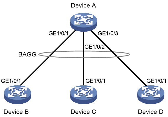
Network configuration
Device B, Device C, and Device D are standalone devices. As shown in Figure 1, configure Device B, Device C, and Device D as S-MLAG devices to establish a multidevice aggregate link with Device A.
Analysis
To establish a multidevice aggregate link with Device A, you must perform the following tasks on Device B, Device C, and Device D:
1. Create a Layer 2 dynamic aggregate interface and assign GigabitEthernet 1/0/1 to its aggregation group.
2. Assign the aggregate interfaces to the same DR group.
Applicable hardware and software versions
The following matrix shows the hardware and software versions to which this configuration example is applicable:
|
Hardware |
Software version |
|
S6812 switch series S6813 switch series |
Release 6615Pxx, Release 6628Pxx |
|
S6550XE-HI switch series |
Release 6008 and later, Release 8106Pxx |
|
S6525XE-HI switch series |
Release 6008 and later, Release 8106Pxx |
|
S5850 switch series |
Release 8005 and later |
|
S5570S-EI switch series |
Release 11xx |
|
S5560X-EI switch series |
Release 63xx, Release 65xx, Release 6615Pxx, Release 6628Pxx |
|
S5560X-HI switch series |
Release 63xx, Release 65xx, Release 6615Pxx, Release 6628Pxx |
|
S5500V2-EI switch series |
Release 63xx, Release 65xx, Release 6615Pxx, Release 6628Pxx |
|
MS4520V2-30F switch |
Release 63xx, Release 65xx, Release 6615Pxx, Release 6628Pxx |
|
MS4520V2-30C switch MS4520V2-54C switch |
Release 65xx, Release 6615Pxx, Release 6628Pxx |
|
MS4520V2-28S switch MS4520V2-24TP switch |
Release 63xx |
|
S6520X-HI switch series S6520X-EI switch series |
Release 63xx, Release 65xx, Release 6615Pxx, Release 6628Pxx |
|
S6520X-SI switch series S6520-SI switch series |
Release 63xx, Release 65xx, Release 6615Pxx, Release 6628Pxx |
|
S5000-EI switch series |
Release 63xx, Release 65xx, Release 6615Pxx, Release 6628Pxx |
|
MS4600 switch series |
Release 63xx, Release 65xx, Release 6615Pxx, Release 6628Pxx |
|
ES5500 switch series |
Release 63xx, Release 65xx, Release 6615Pxx, Release 6628Pxx |
|
S5560S-EI switch series S5560S-SI switch series |
Release 63xx |
|
S5500V3-24P-SI switch S5500V3-48P-SI switch |
Release 63xx |
|
S5500V3-SI switch series (except S5500V3-24P-SI and S5500V3-48P-SI) |
Release 11xx |
|
S5170-EI switch series |
Release 11xx |
|
S5130S-HI switch series S5130S-EI switch series S5130S-SI switch series S5130S-LI switch series |
Release 63xx |
|
S5120V2-SI switch series S5120V2-LI switch series |
Release 63xx |
|
S5120V3-EI switch series |
Release 11xx |
|
S5120V3-36F-SI S5120V3-28P-HPWR-SI S5120V3-54P-PWR-SI |
Release 11xx |
|
S5120V3-SI switch series (except S5120V3-36F-SI, S5120V3-28P-HPWR-SI, and S5120V3-54P-PWR-SI) |
Release 63xx |
|
S5120V3-LI switch series |
Release 63xx |
|
S3600V3-EI switch series |
Release 11xx |
|
S3600V3-SI switch series |
Release 11xx |
|
S5120V3-EI switch series |
Release 11xx |
|
S3100V3-EI switch series S3100V3-SI switch series |
Release 63xx |
|
S5110V2 switch series |
Release 63xx |
|
S5110V2-SI switch series |
Release 63xx |
|
S5000V3-EI switch series S5000V5-EI switch series |
Release 63xx |
|
S5000E-X switch series S5000X-EI switch series |
Release 63xx |
|
E128C switch E152C switch E500C switch series E500D switch series |
Release 63xx |
|
MS4320V2 switch series MS4320V3 switch series MS4300V2 switch series MS4320 switch series MS4200 switch series |
Release 63xx |
|
WS5850-WiNet switch series |
Release 63xx |
|
WS5820-WiNet switch series WS5810-WiNet switch series |
Release 63xx |
|
WAS6000 switch series |
Release 63xx |
|
IE4300-12P-AC switch IE4300-12P-PWR switch IE4300-M switch series IE4320 switch series |
Release 63xx |
Restrictions and guidelines
Before you assign an interface to an aggregation group, use the display this command in interface view to identify whether attribute settings exist, including port isolation, QinQ, VLAN, and VLAN mapping settings. If attribute settings exist, use the corresponding undo commands to remove them.
Configure the link aggregation settings other than S-MLAG settings on each S-MLAG device. Make sure the settings are consistent across the S-MLAG devices.
As a best practice, maintain consistency across S-MLAG devices in service feature configuration.
Procedures
Configuring Device A
# Create Layer 2 aggregate interface Bridge-Aggregation 10, and set the link aggregation mode to dynamic.
<DeviceA> system-view
[DeviceA] interface bridge-aggregation 10
[DeviceA-Bridge-Aggregation10] link-aggregation mode dynamic
[DeviceA-Bridge-Aggregation10] quit
# Assign GigabitEthernet 1/0/1 through GigabitEthernet 1/0/3 to aggregation group 10.
[DeviceA] interface gigabitethernet 1/0/1
[DeviceA-GigabitEthernet1/0/1] port link-aggregation group 10
[DeviceA-GigabitEthernet1/0/1] quit
[DeviceA] interface gigabitethernet 1/0/2
[DeviceA-GigabitEthernet1/0/2] port link-aggregation group 10
[DeviceA-GigabitEthernet1/0/2] quit
[DeviceA] interface gigabitethernet 1/0/3
[DeviceA-GigabitEthernet1/0/3] port link-aggregation group 10
[DeviceA-GigabitEthernet1/0/3] quit
Configuring Device B
# Set the LACP system MAC address to 0001-0001-0001.
<DeviceB> system-view
[DeviceB] lacp system-mac 1-1-1
# Set the LACP system priority to 123.
[DeviceB] lacp system-priority 123
# Set the LACP system number to 1.
[DeviceB] lacp system-number 1
# Create Layer 2 aggregate interface Bridge-Aggregation 2, and set the link aggregation mode to dynamic.
[DeviceB] interface bridge-aggregation 2
[DeviceB-Bridge-Aggregation2] link-aggregation mode dynamic
# Assign Bridge-Aggregation 2 to S-MLAG group 100.
[DeviceB-Bridge-Aggregation2] port s-mlag group 100
[DeviceB-Bridge-Aggregation2] quit
# Assign GigabitEthernet 1/0/1 to aggregation group 2.
[DeviceB] interface gigabitethernet 1/0/1
[DeviceB-GigabitEthernet1/0/1] port link-aggregation group 2
[DeviceB-GigabitEthernet1/0/1] quit
Configuring Device C
# Set the LACP system MAC address to 0001-0001-0001.
<DeviceC> system-view
[DeviceC] lacp system-mac 1-1-1
# Set the LACP system priority to 123.
[DeviceC] lacp system-priority 123
# Set the LACP system number to 2.
[DeviceC] lacp system-number 2
# Create Layer 2 aggregate interface Bridge-Aggregation 3, and set the link aggregation mode to dynamic.
[DeviceC] interface bridge-aggregation 3
[DeviceC-Bridge-Aggregation3] link-aggregation mode dynamic
# Assign Bridge-Aggregation 3 to S-MLAG group 100.
[DeviceC-Bridge-Aggregation3] port s-mlag group 100
# Assign GigabitEthernet 1/0/1 to aggregation group 3.
[DeviceC] interface gigabitethernet 1/0/1
[DeviceC-GigabitEthernet1/0/1] port link-aggregation group 3
[DeviceC-GigabitEthernet1/0/1] quit
Configuring Device D
# Set the LACP system MAC address to 0001-0001-0001.
<DeviceD> system-view
[DeviceD] lacp system-mac 1-1-1
# Set the LACP system priority to 123.
[DeviceD] lacp system-priority 123
# Set the LACP system number to 3.
[DeviceD] lacp system-number 3
# Create Layer 2 aggregate interface Bridge-Aggregation 4, and set the link aggregation mode to dynamic.
[DeviceD] interface bridge-aggregation 4
[DeviceD-Bridge-Aggregation4] link-aggregation mode dynamic
# Assign Bridge-Aggregation 4 to S-MLAG group 100.
[DeviceD-Bridge-Aggregation4] port s-mlag group 100
# Assign GigabitEthernet 1/0/1 to aggregation group 4.
[DeviceD] interface gigabitethernet 1/0/1
[DeviceD-GigabitEthernet1/0/1] port link-aggregation group 4
[DeviceD-GigabitEthernet1/0/1] quit
Verifying the configuration
# Verify that GigabitEthernet 1/0/1 through GigabitEthernet 1/0/3 on Device A are Selected ports.
[DeviceA] display link-aggregation verbose
Loadsharing Type: Shar -- Loadsharing, NonS -- Non-Loadsharing
Port Status: S -- Selected, U -- Unselected, I -- Individual
Port: A -- Auto port, M -- Management port, R -- Reference port
Flags: A -- LACP_Activity, B -- LACP_Timeout, C -- Aggregation,
D -- Synchronization, E -- Collecting, F -- Distributing,
G -- Defaulted, H -- Expired
Aggregate Interface: Bridge-Aggregation10
Creation Mode: Manual
Aggregation Mode: Dynamic
Loadsharing Type: Shar
Management VLANs: None
System ID: 0x8000, a0c7-9afd-0100
Local:
Port Status Priority Index Oper-Key Flag
GE1/0/1 S 32768 1 1 {ACDEF}
GE1/0/2 S 32768 2 1 {ACDEF}
GE1/0/3 S 32768 3 1 {ACDEF}
Remote:
Actor Priority Index Oper-Key SystemID Flag
GE1/0/1(R) 32768 16385 50100 0x7b , 0001-0001-0001 {ACDEF}
GE1/0/2 32768 32769 50100 0x7b , 0001-0001-0001 {ACDEF}
GE1/0/3 32768 49153 50100 0x7b , 0001-0001-0001 {ACDEF}
Configuration files
|
|
IMPORTANT: Support for the port link-mode bridge command depends on the device model. |
· Device A:
#
interface Bridge-Aggregation10
link-aggregation mode dynamic
#
interface GigabitEthernet1/0/1
port link-mode bridge
combo enable fiber
port link-aggregation group 10
#
interface GigabitEthernet1/0/2
port link-mode bridge
combo enable fiber
port link-aggregation group 10
#
interface GigabitEthernet1/0/3
port link-mode bridge
combo enable fiber
port link-aggregation group 10
#
· Device B:
#
lacp system-mac 0001-0001-0001
lacp system-number 1
lacp system-priority 123
#
interface Bridge-Aggregation2
link-aggregation mode dynamic
port s-mlag group 100
#
interface GigabitEthernet1/0/1
port link-mode bridge
combo enable fiber
port link-aggregation group 2
#
· Device C:
#
lacp system-mac 0001-0001-0001
lacp system-number 2
lacp system-priority 123
#
interface Bridge-Aggregation3
link-aggregation mode dynamic
port s-mlag group 100
#
interface GigabitEthernet1/0/1
port link-mode bridge
combo enable fiber
port link-aggregation group 3
#
· Device D:
lacp system-mac 0001-0001-0001
lacp system-number 3
lacp system-priority 123
#
interface Bridge-Aggregation4
link-aggregation mode dynamic
port s-mlag group 100
#
interface GigabitEthernet1/0/1
port link-mode bridge
combo enable fiber
port link-aggregation group 4
#
Example: Aggregating server-side links by using S-MLAG
Network configuration
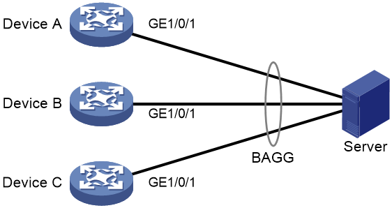
As shown in Figure 2, configure S-MLAG as follows:
· Connect GigabitEthernet 1/0/1 interfaces on Device A, Device B, and Device C to the server, and configure S-MLAG to aggregate the links to the server.
· Configure the server-facing aggregate interfaces on Device A, Device B, and Device C as edge aggregate interfaces for the aggregation member ports to forward traffic correctly before link aggregation is set up on the server.
Analysis
To create a multichassis aggregate link on Device A, Device B, and Device C, perform the following tasks:
· Create server-facing Layer 2 dynamic aggregate interfaces.
· Assign the aggregate interfaces to an S-MLAG group.
Applicable hardware and software versions
The following matrix shows the hardware and software versions to which this configuration example is applicable:
|
Hardware |
Software version |
|
S6812 switch series S6813 switch series |
Release 6615Pxx, Release 6628Pxx |
|
S6550XE-HI switch series |
Release 6008 and later, Release 8106Pxx |
|
S6525XE-HI switch series |
Release 6008 and later, Release 8106Pxx |
|
S5850 switch series |
Release 8005 and later |
|
S5570S-EI switch series |
Release 11xx |
|
S5560X-EI switch series |
Release 63xx , Release 65xx , Release 6615Pxx, Release 6628Pxx |
|
S5560X-HI switch series |
Release 63xx , Release 65xx , Release 6615Pxx, Release 6628Pxx |
|
S5500V2-EI switch series |
Release 63xx , Release 65xx , Release 6615Pxx, Release 6628Pxx |
|
MS4520V2-30F switch |
Release 63xx , Release 65xx , Release 6615Pxx, Release 6628Pxx |
|
MS4520V2-30C switch MS4520V2-54C switch |
Release 65xx , Release 6615Pxx, Release 6628Pxx |
|
MS4520V2-28S switch MS4520V2-24TP switch |
Release 63xx |
|
S6520X-HI switch series S6520X-EI switch series |
Release 63xx , Release 65xx , Release 6615Pxx, Release 6628Pxx |
|
S6520X-SI switch series S6520-SI switch series |
Release 63xx , Release 65xx , Release 6615Pxx, Release 6628Pxx |
|
S5000-EI switch series |
Release 63xx , Release 65xx , Release 6615Pxx, Release 6628Pxx |
|
MS4600 switch series |
Release 63xx , Release 65xx , Release 6615Pxx, Release 6628Pxx |
|
ES5500 switch series |
Release 63xx , Release 65xx , Release 6615Pxx, Release 6628Pxx |
|
S5560S-EI switch series S5560S-SI switch series |
Release 63xx |
|
S5500V3-24P-SI switch S5500V3-48P-SI switch |
Release 63xx |
|
S5500V3-SI switch series (except S5500V3-24P-SI and S5500V3-48P-SI) |
Release 11xx |
|
S5170-EI switch series |
Release 11xx |
|
S5130S-HI switch series S5130S-EI switch series S5130S-SI switch series S5130S-LI switch series |
Release 63xx |
|
S5120V2-SI switch series S5120V2-LI switch series |
Release 63xx |
|
S5120V3-EI switch series |
Release 11xx |
|
S5120V3-36F-SI switch S5120V3-28P-HPWR-SI switch S5120V3-54P-PWR-SI switch |
Release 11xx |
|
S5120V3-SI switch series (except S5120V3-36F-SI, S5120V3-28P-HPWR-SI, and S5120V3-54P-PWR-SI) |
Release 63xx |
|
S5120V3-LI switch series |
Release 63xx |
|
S3600V3-EI switch series |
Release 11xx |
|
S3600V3-SI switch series |
Release 11xx |
|
S3100V3-EI switch series S3100V3-SI switch series |
Release 63xx |
|
S5110V2 switch series |
Release 63xx |
|
S5110V2-SI switch series |
Release 63xx |
|
S5000V3-EI switch series S5000V5-EI switch series |
Release 63xx |
|
S5000E-X switch S5000X-EI switch series |
Release 63xx |
|
E128C switch E152C switch E500C switch series E500D switch series |
Release 63xx |
|
MS4320V2 switch series MS4320V3 switch series MS4300V2 switch series MS4320 switch series MS4200 switch series |
Release 63xx |
|
WS5850-WiNet switch series |
Release 63xx |
|
WS5820-WiNet switch series WS5810-WiNet switch series |
Release 63xx |
|
WAS6000 switch series |
Release 63xx |
|
IE4300-12P-AC switch IE4300-12P-PWR switch IE4300-M switch series IE4320 switch series |
Release 63xx |
Restrictions and guidelines
When you configure S-MLAG, follow these restrictions and guidelines:
· When you assign a port to an aggregation group, the recommended configuration procedure is as follows:
a. Use the display this command in interface view to check the following attribute configurations of the port:
- Port isolation.
- QinQ.
- VLAN.
- VLAN mapping.
b. If any of the above configurations exist, use the undo forms of the corresponding commands to remove these configurations. This enables the port to use the default attribute configurations.
c. Assign the port to the aggregation group.
· Make sure the S-MLAG member devices have consistent link aggregation configuration.
· To ensure correct service traffic forwarding, configure the same service settings on the S-MLAG member devices.
Procedures
Configuring Device A
# Set the LACP system MAC address to 0001-0001-0001.
<DeviceA> system-view
[DeviceA] lacp system-mac 1-1-1
# Set the LACP system priority to 123.
[DeviceA] lacp system-priority 123
# Set the LACP system number to 1.
[DeviceA] lacp system-number 1
# Create Layer 2 aggregate interface Bridge-Aggregation 1, and set the link aggregation mode to dynamic.
[DeviceA] interface bridge-aggregation 1
[DeviceA-Bridge-Aggregation1] link-aggregation mode dynamic
# Configure Bridge-Aggregation 1 as an edge aggregate interface.
[DeviceA-Bridge-Aggregation1] lacp edge-port
# Assign Bridge-Aggregation 1 to S-MLAG group 100.
[DeviceA-Bridge-Aggregation1] port s-mlag group 100
[DeviceA-Bridge-Aggregation1] quit
# Assign GigabitEthernet 1/0/1 to aggregation group 1.
[DeviceA] interface gigabitethernet 1/0/1
[DeviceA-GigabitEthernet1/0/1] port link-aggregation group 1
[DeviceA-GigabitEthernet1/0/1] quit
Configuring Device B
# Set the LACP system MAC address to 0001-0001-0001.
<DeviceB> system-view
[DeviceB] lacp system-mac 1-1-1
# Set the LACP system priority to 123.
[DeviceB] lacp system-priority 123
# Set the LACP system number to 2.
[DeviceB] lacp system-number 2
# Create Layer 2 aggregate interface Bridge-Aggregation 2, and set the link aggregation mode to dynamic.
[DeviceB] interface bridge-aggregation 2
[DeviceC-Bridge-Aggregation2] link-aggregation mode dynamic
# Configure Bridge-Aggregation 2 as an edge aggregate interface.
[DeviceB-Bridge-Aggregation2] lacp edge-port
# Assign Bridge-Aggregation 2 to S-MLAG group 100.
[DeviceB-Bridge-Aggregation2] port s-mlag group 100
# Assign GigabitEthernet 1/0/1 to aggregation group 2.
[DeviceB] interface gigabitethernet 1/0/1
[DeviceB-GigabitEthernet1/0/1] port link-aggregation group 2
[DeviceB-GigabitEthernet1/0/1] quit
Configuring Device C
# Set the LACP system MAC address to 0001-0001-0001.
<DeviceC> system-view
[DeviceC] lacp system-mac 1-1-1
# Set the LACP system priority to 123.
[DeviceC] lacp system-priority 123
# Set the LACP system number to 3.
[DeviceC] lacp system-number 3
# Create Layer 2 aggregate interface Bridge-Aggregation 3, and set the link aggregation mode to dynamic.
[DeviceC] interface bridge-aggregation 3
[DeviceC-Bridge-Aggregation3] link-aggregation mode dynamic
# Configure Bridge-Aggregation 3 as an edge aggregate interface.
[DeviceC-Bridge-Aggregation3] lacp edge-port
# Assign Bridge-Aggregation 3 to S-MLAG group 100.
[DeviceC-Bridge-Aggregation3] port s-mlag group 100
# Assign GigabitEthernet 1/0/1 to aggregation group 3.
[DeviceC] interface gigabitethernet 1/0/1
[DeviceC-GigabitEthernet1/0/1] port link-aggregation group 3
[DeviceC-GigabitEthernet1/0/1] quit
Verifying the configuration
# Before you configure dynamic link aggregation on the server, verify that the aggregation member ports are in individual state on Device A, Device B, and Device C to forward traffic independently.
[DeviceA] display link-aggregation verbose
Loadsharing Type: Shar -- Loadsharing, NonS -- Non-Loadsharing
Port Status: S -- Selected, U -- Unselected, I -- Individual
Port: A -- Auto port, M -- Management port, R -- Reference port
Flags: A -- LACP_Activity, B -- LACP_Timeout, C -- Aggregation,
D -- Synchronization, E -- Collecting, F -- Distributing,
G -- Defaulted, H -- Expired
Aggregate Interface: Bridge-Aggregation1
Creation Mode: Manual
Aggregation Mode: Dynamic
Loadsharing Type: Shar
Management VLANs: None
System ID: 0x7b, 0001-0001-0001
Local:
Port Status Priority Index Oper-Key Flag
GE1/0/1 I 32768 16385 50100 {AG}
Remote:
Actor Priority Index Oper-Key SystemID Flag
GE1/0/1 32768 0 0 0x8000, 0000-0000-0000 {DEF}
[DeviceB] display link-aggregation verbose
Loadsharing Type: Shar -- Loadsharing, NonS -- Non-Loadsharing
Port Status: S -- Selected, U -- Unselected, I -- Individual
Port: A -- Auto port, M -- Management port, R -- Reference port
Flags: A -- LACP_Activity, B -- LACP_Timeout, C -- Aggregation,
D -- Synchronization, E -- Collecting, F -- Distributing,
G -- Defaulted, H -- Expired
Aggregate Interface: Bridge-Aggregation2
Creation Mode: Manual
Aggregation Mode: Dynamic
Loadsharing Type: Shar
Management VLANs: None
System ID: 0x7b, 0001-0001-0001
Local:
Port Status Priority Index Oper-Key Flag
GE1/0/1 I 32768 32769 50100 {AG}
Remote:
Actor Priority Index Oper-Key SystemID Flag
GE1/0/1 32768 0 0 0x8000, 0000-0000-0000 {DEF}
[DeviceC] display link-aggregation verbose
Loadsharing Type: Shar -- Loadsharing, NonS -- Non-Loadsharing
Port Status: S -- Selected, U -- Unselected, I -- Individual
Port: A -- Auto port, M -- Management port, R -- Reference port
Flags: A -- LACP_Activity, B -- LACP_Timeout, C -- Aggregation,
D -- Synchronization, E -- Collecting, F -- Distributing,
G -- Defaulted, H -- Expired
Aggregate Interface: Bridge-Aggregation3
Creation Mode: Manual
Aggregation Mode: Dynamic
Loadsharing Type: Shar
Management VLANs: None
System ID: 0x7b, 0001-0001-0001
Local:
Port Status Priority Index Oper-Key Flag
GE1/0/1 I 32768 49153 50100 {AG}
Remote:
Actor Priority Index Oper-Key SystemID Flag
GE1/0/1 32768 0 0 0x8000, 0000-0000-0000 {DEF}
# After you configure dynamic link aggregation on the server, verify that the aggregation member ports are selected on Device A, Device B, and Device C, which indicates that the multichassis link aggregation has been set up.
[DeviceA] display link-aggregation verbose
Loadsharing Type: Shar -- Loadsharing, NonS -- Non-Loadsharing
Port Status: S -- Selected, U -- Unselected, I -- Individual
Port: A -- Auto port, M -- Management port, R -- Reference port
Flags: A -- LACP_Activity, B -- LACP_Timeout, C -- Aggregation,
D -- Synchronization, E -- Collecting, F -- Distributing,
G -- Defaulted, H -- Expired
Aggregate Interface: Bridge-Aggregation1
Creation Mode: Manual
Aggregation Mode: Dynamic
Loadsharing Type: Shar
Management VLANs: None
System ID: 0x7b, 0001-0001-0001
Local:
Port Status Priority Index Oper-Key Flag
GE1/0/1(R) S 32768 16385 50100 {ACDEF}
Remote:
Actor Priority Index Oper-Key SystemID Flag
GE1/0/1 32768 1 1 0x8000, 5022-e533-0400 {ACDEF}
[DeviceB] display link-aggregation verbose
Loadsharing Type: Shar -- Loadsharing, NonS -- Non-Loadsharing
Port Status: S -- Selected, U -- Unselected, I -- Individual
Port: A -- Auto port, M -- Management port, R -- Reference port
Flags: A -- LACP_Activity, B -- LACP_Timeout, C -- Aggregation,
D -- Synchronization, E -- Collecting, F -- Distributing,
G -- Defaulted, H -- Expired
Aggregate Interface: Bridge-Aggregation2
Creation Mode: Manual
Aggregation Mode: Dynamic
Loadsharing Type: Shar
Management VLANs: None
System ID: 0x7b, 0001-0001-0001
Local:
Port Status Priority Index Oper-Key Flag
GE1/0/1(R) S 32768 32769 50100 {ACDEF}
Remote:
Actor Priority Index Oper-Key SystemID Flag
GE1/0/1 32768 2 1 0x8000, 5022-e533-0400 {ACDEF}
[DeviceC] display link-aggregation verbose
Loadsharing Type: Shar -- Loadsharing, NonS -- Non-Loadsharing
Port Status: S -- Selected, U -- Unselected, I -- Individual
Port: A -- Auto port, M -- Management port, R -- Reference port
Flags: A -- LACP_Activity, B -- LACP_Timeout, C -- Aggregation,
D -- Synchronization, E -- Collecting, F -- Distributing,
G -- Defaulted, H -- Expired
Aggregate Interface: Bridge-Aggregation3
Creation Mode: Manual
Aggregation Mode: Dynamic
Loadsharing Type: Shar
Management VLANs: None
System ID: 0x7b, 0001-0001-0001
Local:
Port Status Priority Index Oper-Key Flag
GE1/0/1(R) S 32768 49153 50100 {ACDEF}
Remote:
Actor Priority Index Oper-Key SystemID Flag
GE1/0/1 32768 3 1 0x8000, 5022-e533-0400 {ACDEF}
Configuration files
|
|
IMPORTANT: Support for the port link-mode bridge command depends on the device model. |
· Device A:
#
lacp system-mac 0001-0001-0001
lacp system-number 1
lacp system-priority 123
#
interface Bridge-Aggregation1
link-aggregation mode dynamic
lacp edge-port
port s-mlag group 100
#
interface GigabitEthernet1/0/1
port link-mode bridge
port link-aggregation group 1
#
· Device B:
#
lacp system-mac 0001-0001-0001
lacp system-number 2
lacp system-priority 123
#
interface Bridge-Aggregation2
link-aggregation mode dynamic
lacp edge-port
port s-mlag group 100
#
interface GigabitEthernet1/0/1
port link-mode bridge
port link-aggregation group 2
#
· Device C:
#
lacp system-mac 0001-0001-0001
lacp system-number 3
lacp system-priority 123
#
interface Bridge-Aggregation3
link-aggregation mode dynamic
lacp edge-port
port s-mlag group 100
#
interface GigabitEthernet1/0/1
port link-mode bridge
port link-aggregation group 3
#
