- Table of Contents
-
- H3C Fixed Port Campus Switches Configuration Examples-6W104
- 00-Applicable hardware and software versions
- 01-Login Management Configuration Examples
- 02-RBAC Configuration Examples
- 03-Software Upgrade Examples
- 04-ISSU Configuration Examples
- 05-Software Patching Examples
- 06-Ethernet Link Aggregation Configuration Examples
- 07-Port Isolation Configuration Examples
- 08-Spanning Tree Configuration Examples
- 09-VLAN Configuration Examples
- 10-VLAN Tagging Configuration Examples
- 11-DHCP Snooping Configuration Examples
- 12-Cross-Subnet Dynamic IP Address Allocation Configuration Examples
- 13-IPv6 over IPv4 Tunneling with OSPFv3 Configuration Examples
- 14-IPv6 over IPv4 GRE Tunnel Configuration Examples
- 15-GRE with OSPF Configuration Examples
- 16-OSPF Configuration Examples
- 17-IS-IS Configuration Examples
- 18-BGP Configuration Examples
- 19-Policy-Based Routing Configuration Examples
- 20-OSPFv3 Configuration Examples
- 21-IPv6 IS-IS Configuration Examples
- 22-Routing Policy Configuration Examples
- 23-IGMP Snooping Configuration Examples
- 24-IGMP Configuration Examples
- 25-MLD Snooping Configuration Examples
- 26-IPv6 Multicast VLAN Configuration Examples
- 27-ACL Configuration Examples
- 28-Traffic Policing Configuration Examples
- 29-GTS and Rate Limiting Configuration Examples
- 30-Traffic Filtering Configuration Examples
- 31-AAA Configuration Examples
- 32-Port Security Configuration Examples
- 33-Portal Configuration Examples
- 34-SSH Configuration Examples
- 35-IP Source Guard Configuration Examples
- 36-Ethernet OAM Configuration Examples
- 37-CFD Configuration Examples
- 38-DLDP Configuration Examples
- 39-VRRP Configuration Examples
- 40-BFD Configuration Examples
- 41-NTP Configuration Examples
- 42-SNMP Configuration Examples
- 43-NQA Configuration Examples
- 44-Mirroring Configuration Examples
- 45-sFlow Configuration Examples
- 46-OpenFlow Configuration Examples
- 47-MAC Address Table Configuration Examples
- 48-Static Multicast MAC Address Entry Configuration Examples
- 49-IP Unnumbered Configuration Examples
- 50-MVRP Configuration Examples
- 51-MCE Configuration Examples
- 52-Attack Protection Configuration Examples
- 53-Smart Link Configuration Examples
- 54-RRPP Configuration Examples
- 55-BGP Route Selection Configuration Examples
- 56-IS-IS Route Summarization Configuration Examples
- 57-VXLAN Configuration Examples
- 58-DRNI Configuration Examples
- 59-IRF 3.1 Configuration Examples
- 60-PTP Configuration Examples
- 61-S-MLAG Configuration Examples
- 62-Puppet Configuration Examples
- 63-802.1X Configuration Examples
- 64-MAC Authentication Configuration Examples
- 65-ISATAP Tunnel and 6to4 Tunnel Configuration Examples
- 66-BIDIR-PIM Configuration Examples
- 67-Congestion Avoidance and Queue Scheduling Configuration Examples
- 68-Basic MPLS Configuration Examples
- 69-MPLS L3VPN Configuration Examples
- 70-MPLS OAM Configuration Examples
- 71-EVPN-DCI over an MPLS L3VPN Network Configuration Examples
- 72-DRNI and EVPN Configuration Examples
- 73-Multicast VPN Configuration Examples
- 74-MPLS TE Configuration Examples
- 75-Control Plane-Based QoS Policy Configuration Examples
- 76-Priority Mapping and Queue Scheduling Configuration Examples
- 77-ARP Attack Protection Configuration Examples
- 78-IRF Software Upgrade Configuration Examples
- 79-IRF Member Replacement Configuration Examples
- 80-Layer 3 Multicast on Multicast Source-Side DR System Configuration Examples
- 81-EVPN Multicast Configuration Examples
- Related Documents
-
| Title | Size | Download |
|---|---|---|
| 73-Multicast VPN Configuration Examples | 228.80 KB |
Example: Configuring intra-AS MDT-based MVPN
Applicable hardware and software versions
Example: Configuring inter-AS option A MDT-based MVPN
Applicable hardware and software versions
Example: Configuring inter-AS option C MDT-based MVPN
Introduction
This document provides multicast VPN configuration examples.
Prerequisites
The configuration examples in this document were created and verified in a lab environment, and all the devices were started with the factory default configuration. When you are working on a live network, make sure you understand the potential impact of every command on your network.
This document assumes that you have basic knowledge of multicast VPN.
Example: Configuring intra-AS MDT-based MVPN
Network configuration
· Customer A has two branches that connect to the MPLS L3VPN network of a service provider.
· PIM-SM runs within the two branches.
· The multicast source and the receiver host are in different branches.
Configure intra-AS MDT-based MVPN so that the receiver host can receive the multicast data from the source.
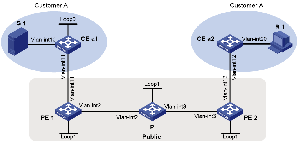
Table 1 Interface and IP address assignment
|
Device |
Interface |
IP address |
Device |
Interface |
IP address |
|
S 1 |
— |
10.11.3.2/24 |
PE 2 |
Vlan-int3 |
192.168.2.2/24 |
|
PE 1 |
Vlan-int2 |
192.168.1.2/24 |
PE 2 |
Vlan-int12 |
10.11.2.1/24 |
|
PE 1 |
Vlan-int11 |
10.11.1.1/24 |
PE 2 |
Loop1 |
1.1.1.2/32 |
|
PE 1 |
Loop1 |
1.1.1.1/32 |
CE a1 |
Vlan-int10 |
10.11.3.1/24 |
|
P |
Vlan-int2 |
192.168.1.1/24 |
CE a1 |
Vlan-int11 |
10.11.1.2/24 |
|
P |
Vlan-int3 |
192.168.2.1/24 |
CE a1 |
Loop0 |
2.2.2.2/32 |
|
P |
Loop1 |
3.3.3.3/32 |
CE a2 |
Vlan-int20 |
10.11.4.1/24 |
|
R 1 |
— |
10.11.4.2/24 |
CE a2 |
Vlan-int12 |
10.11.2.2/24 |
Analysis
To meet the network requirement, you must run PIM on the devices of the public network, and configure MDT-based MVPN on each PE. In addition, make sure the PIM protocol on the public network is independent from the PIM protocol for the VPN instance.
Applicable hardware and software versions
The following matrix shows the hardware and software versions to which this configuration example is applicable:
|
Hardware |
Software version |
|
S6812 switch series S6813 switch series |
Not supported |
|
S6550XE-HI switch series |
Release 6008 and later, Release 8106Pxx |
|
S6525XE-HI switch series |
Release 6008 and later, Release 8106Pxx |
|
S5850 switch series |
Not supported |
|
S5570S-EI switch series |
Not supported |
|
S5560X-EI switch series |
Not supported |
|
S5560X-HI switch series |
Not supported |
|
S5500V2-EI switch series |
Not supported |
|
MS4520V2-30F switch |
Not supported |
|
MS4520V2-30C switch MS4520V2-54C switch |
Not supported |
|
MS4520V2-28S switch MS4520V2-24TP switch |
Not supported |
|
S6520X-HI switch series S6520X-EI switch series |
Not supported |
|
S6520X-SI switch series S6520-SI switch series |
Not supported |
|
S5000-EI switch series |
Not supported |
|
MS4600 switch series |
Not supported |
|
ES5500 switch series |
Not supported |
|
S5560S-EI switch series S5560S-SI switch series |
Not supported |
|
S5500V3-24P-SI S5500V3-48P-SI |
Not supported |
|
S5500V3-SI switch series (except S5500V3-24P-SI and S5500V3-48P-SI) |
Not supported |
|
S5170-EI switch series |
Not supported |
|
S5130S-HI switch series S5130S-EI switch series S5130S-SI switch series S5130S-LI switch series |
Not supported |
|
S5120V2-SI switch series S5120V2-LI switch series |
Not supported |
|
S5120V3-EI switch series |
Not supported |
|
S5120V3-36F-SI S5120V3-28P-HPWR-SI S5120V3-54P-PWR-SI |
Not supported |
|
S5120V3-SI switch series (except S5120V3-36F-SI, S5120V3-28P-HPWR-SI, and S5120V3-54P-PWR-SI) |
Not supported |
|
S5120V3-LI switch series |
Not supported |
|
S3600V3-EI switch series |
Not supported |
|
S3600V3-SI switch series |
Not supported |
|
S3100V3-EI switch series S3100V3-SI switch series |
Not supported |
|
S5110V2 switch series |
Not supported |
|
S5110V2-SI switch series |
Not supported |
|
S5000V3-EI switch series S5000V5-EI switch series |
Not supported |
|
S5000E-X switch series S5000X-EI switch series |
Not supported |
|
E128C switch E152C switch E500C switch series E500D switch series |
Not supported |
|
MS4320V2 switch series MS4320V3 switch series MS4300V2 switch series MS4320 switch series MS4200 switch series |
Not supported |
|
WS5850-WiNet switch series |
Not supported |
|
WS5820-WiNet switch series WS5810-WiNet switch series |
Not supported |
|
WAS6000 switch series |
Not supported |
|
IE4300-12P-AC switch IE4300-12P-PWR switch IE4300-M switch series IE4320 switch series |
Not supported |
Restrictions and guidelines
When you configure the intra-AS MDT-based MVPN, follow these restrictions and guidelines:
· The MTI interfaces take effect only after the default-group and the MVPN source interface are specified and the MVPN source interface obtains the public IP address.
· To ensure correct MTI forwarding, you must create a service loopback group and specify the multicast tunnel service type by using the service-loopback group command. For more information about this command, see Layer 2—LAN Switching Command Reference.
· You must enable the same PIM mode on all interfaces that belong to the same VPN instance (including the interfaces associated with the VPN instance on the PEs).
· You must specify the same default-group for the same VPN instance on different PEs.
· The IP address of the MVPN source interface must be the same as the source address used for establishing BGP peer relationship. Otherwise, correct routing information cannot be obtained.
Procedures
1. Assign an IP address and subnet mask to each interface on CE a1, as shown in Table 1.
<CEa1> system-view
[CEa1] interface vlan-interface 10
[CEa1-Vlan-interface10] ip address 10.11.3.1 24
[CEa1-Vlan-interface10] quit
[CEa1] interface loopback 0
[CEa1-LoopBack0] ip address 2.2.2.2 32
[CEa1-LoopBack0] quit
[CEa1] interface vlan-interface 11
[CEa1-Vlan-interface11] ip address 10.11.1.2 24
[CEa1-Vlan-interface11] quit
# Configure PE 1, P, PE 2, and CE a2 in the same way CE a1 is configured. (Details not shown.)
2. Configure a unicast routing protocol and basic MPLS VPN on all devices so that all devices are interoperable at the network layer. (Details not shown.)
For more information about configuring basic MPLS VPN, see MPLS Configuration Guide.
3. Enable IP multicast routing on the public network, and enable PIM-SM on the public network interfaces (including Loopback interfaces):
# On PE 1, enable IP multicast routing, and enable PIM-SM on the public network interfaces.
[PE1] multicast routing
[PE1-mrib] quit
[PE1] interface vlan-interface 2
[PE1-Vlan-interface2] pim sm
[PE1-Vlan-interface2] quit
[PE1] interface loopback 1
[PE1-LoopBack1] pim sm
[PE1-LoopBack1] quit
# On P, enable IP multicast routing, and enable PIM-SM on the public network interfaces.
[P] multicast routing
[P-mrib] quit
[P] interface vlan-interface 2
[P-Vlan-interface2] pim sm
[P-Vlan-interface2] quit
[P] interface vlan-interface 3
[P-Vlan-interface3] pim sm
[P-Vlan-interface3] quit
[P] interface loopback 1
[P-LoopBack1] pim sm
[P-LoopBack1] quit
# Configure Loopback 1 as a C-BSR and a C-RP.
[P] pim
[P-pim] c-bsr 3.3.3.3
[P-pim] c-rp 3.3.3.3
[P-pim] quit
# On PE 2, enable IP multicast routing, and enable PIM-SM on the public network interfaces.
[PE2] multicast routing
[PE2-mrib] quit
[PE2] interface vlan-interface 3
[PE2-Vlan-interface3] pim sm
[PE2-Vlan-interface3] quit
[PE2] interface loopback 1
[PE2-LoopBack1] pim sm
[PE2-LoopBack1] quit
4. Enable IP multicast routing for the VPN instance, enable PIM-SM on the private network interfaces, and enable IGMP on interfaces that have receiver hosts attached:
# On CE a1, enable IP multicast routing, and enable PIM-SM on each interface.
[CEa1] multicast routing
[CEa1-mrib] quit
[CEa1] interface vlan-interface 10
[CEa1-Vlan-interface10] pim sm
[CEa1-Vlan-interface10] quit
[CEa1] interface vlan-interface 11
[CEa1-Vlan-interface11] pim sm
[CEa1-Vlan-interface11] quit
[CEa1] interface loopback 0
[CEa1-LoopBack0] pim sm
[CEa1-LoopBack0] quit
# Configure Loopback 0 as a C-BSR and a C-RP.
[CEa1] pim
[CEa1-pim] c-bsr 2.2.2.2
[CEa1-pim] c-rp 2.2.2.2
[CEa1-pim] quit
# On CE a2, enable IP multicast routing, enable PIM-SM on VLAN-interface 12, and enable IGMP on the receiver-side interface VLAN-interface 20.
[CEa2] multicast routing
[CEa2-mrib] quit
[CEa2] interface vlan-interface 12
[CEa2-Vlan-interface12] pim sm
[CEa2-Vlan-interface12] quit
[CEa2] interface vlan-interface 20
[CEa2-Vlan-interface20] igmp enable
[CEa2-Vlan-interface20] quit
# On PE 1, create a VPN instance named customerA.
[PE1] ip vpn-instance customerA
[PE1-vpn-instance-customerA] route-distinguisher 100:1
[PE1-vpn-instance-customerA] vpn-target 111:1
[PE1-vpn-instance-customerA] quit
# Associate VLAN-interface 11 with VPN instance customerA.
[PE1] interface vlan-interface 11
[PE1-Vlan-interface11] ip binding vpn-instance customerA
[PE1-Vlan-interface11] quit
# Enable IP multicast routing for VPN instance customerA.
[PE1] multicast routing vpn-instance customerA
[PE1-mrib-customerA] quit
# Enable PIM-SM on VLAN-interface 11.
[PE1] interface vlan-interface 11
[PE1-Vlan-interface11] pim sm
[PE1-Vlan-interface11] quit
# On PE 2, create a VPN instance named customerA.
[PE2] ip vpn-instance customerA
[PE2-vpn-instance-customerA] route-distinguisher 100:1
[PE2-vpn-instance-customerA] vpn-target 111:1
[PE2-vpn-instance-customerA] quit
# Associate VLAN-interface 12 with VPN instance customerA.
[PE2] interface vlan-interface 12
[PE2-Vlan-interface12] ip binding vpn-instance customerA
[PE2-Vlan-interface12] quit
# Enable IP multicast routing for VPN instance customerA.
[PE2] multicast routing vpn-instance customerA
[PE2-mrib-customerA] quit
# Enable PIM-SM on VLAN-interface 12.
[PE2] interface vlan-interface 12
[PE2-Vlan-interface12] pim sm
[PE2-Vlan-interface12] quit
5. Configure the MVPN for the VPN instance:
# On PE 1, create service loopback group 1 and specify the multicast tunnel service.
[PE1] service-loopback group 1 type multicast-tunnel
# Assign Ten-GigabitEthernet 1/0/4 to service loopback group 1.
[PE1] interface ten-gigabitethernet 1/0/4
[PE1-Ten-GigabitEthernet1/0/4] port service-loopback group 1
[PE1-Ten-GigabitEthernet1/0/4] quit
# Create an MDT-based MVPN for VPN instance customerA.
[PE1] multicast-vpn vpn-instance customerA mode mdt
# Create an MVPN IPv4 address family for VPN instance customerA.
[PE1-mvpn-customerA] address-family ipv4
# Specify the default group, MVPN source interface, and data group range for VPN instance customerA.
[PE1-mvpn-customerA-ipv4] default-group 239.1.1.1
[PE1-mvpn-customerA-ipv4] source loopback 1
[PE1-mvpn-customerA-ipv4] data-group 225.2.2.0 28
[PE1-mvpn-customerA-ipv4] quit
[PE1-mvpn-customerA] quit
# On PE 2, create service loopback group 1 and specify the multicast tunnel service.
[PE2] service-loopback group 1 type multicast-tunnel
# Assign Ten-GigabitEthernet 1/0/4 to service loopback group 1.
[PE2] interface ten-gigabitethernet 1/0/4
[PE2-Ten-GigabitEthernet1/0/4] port service-loopback group 1
[PE2-Ten-GigabitEthernet1/0/4] quit
# Create an MDT-based MVPN for VPN instance customerA.
[PE2] multicast-vpn vpn-instance customerA mode mdt
# Create an MVPN IPv4 address family for VPN instance customerA.
[PE2-mvpn-customerA] address-family ipv4
# Specify the default group, MVPN source interface, and data group range for VPN instance customerA.
[PE2-mvpn-customerA-ipv4] default-group 239.1.1.1
[PE2-mvpn-customerA-ipv4] source loopback 1
[PE2-mvpn-customerA-ipv4] data-group 225.2.2.0 28
[PE2-mvpn-customerA-ipv4] quit
[PE2-mvpn-customerA] quit
Verifying the configuration
# Verify the establishment of the default-MDT for the public network on PEs and P. The following example shows PIM routing table for the public network on P.
[P] display pim routing-table
Total 1 (*, G) entries; 2 (S, G) entries
(*, 239.1.1.1)
RP: 3.3.3.3 (local)
Protocol: pim-sm, Flag: SPT LOC ACT
UpTime: 02:54:43
Upstream interface: Register
Upstream neighbor: NULL
RPF prime neighbor: NULL
Downstream interface(s) information:
Total number of downstreams: 2
1: Vlan-interface2
Protocol: pim-sm, UpTime: 02:54:43, Expires: -
2: Vlan-interface3
Protocol: pim-sm, UpTime: 02:33:57, Expires: -
(1.1.1.1, 239.1.1.1)
RP: 3.3.3.3 (local)
Protocol: pim-sm, Flag: SPT LOC ACT
UpTime: 01:57:13
Upstream interface: Vlan-interface2
Upstream neighbor: 192.168.1.2
RPF prime neighbor: 192.168.1.2
Downstream interface(s) information: None
(1.1.1.2, 239.1.1.1)
RP: 3.3.3.3 (local)
Protocol: pim-sm, Flag: SPT LOC ACT
UpTime: 01:57:13
Upstream interface: Vlan-interface3
Upstream neighbor: 192.168.2.2
RPF prime neighbor: 192.168.2.2
Downstream interface(s) information: None
The output shows that an RPT for (*, 239.1.1.1), an SPT for (1.1.1.1, 239.1.1.1), and an SPT for (1.1.1.2, 239.1.1.1) have been established on the public network. The RPT and SPTs constitute the default-MDT for the public network.
Configuration files
· PE 1:
#
ip vpn-instance customerA
route-distinguisher 100:1
vpn-target 111:1 import-extcommunity
vpn-target 111:1 export-extcommunity
#
service-loopback group 1 type multicast-tunnel
#
vlan 2
#
vlan 11
#
interface LoopBack1
ip address 1.1.1.1 255.255.255.255
pim sm
#
interface Vlan-interface2
ip address 192.168.1.2 255.255.255.0
pim sm
#
interface Vlan-interface11
ip binding vpn-instance customerA
ip address 10.11.1.1 255.255.255.0
pim sm
#
interface Ten-GigabitEthernet1/0/4
port link-mode bridge
port service-loopback group 1
#
multicast routing
#
multicast routing vpn-instance customerA
#
multicast-vpn vpn-instance customerA mode mdt
address-family ipv4
source LoopBack1
default-group 239.1.1.1
data-group 225.2.2.0 255.255.255.240
#
· PE 2:
#
ip vpn-instance customerA
route-distinguisher 100:1
vpn-target 111:1 import-extcommunity
vpn-target 111:1 export-extcommunity
#
service-loopback group 1 type multicast-tunnel
#
vlan 3
#
vlan 12
#
interface LoopBack1
ip address 1.1.1.2 255.255.255.255
pim sm
#
interface Vlan-interface3
ip address 192.168.2.2 255.255.255.0
pim sm
#
interface Vlan-interface12
ip binding vpn-instance customerA
ip address 10.11.2.1 255.255.255.0
pim sm
#
interface Ten-GigabitEthernet1/0/4
port link-mode bridge
port service-loopback group 1
#
multicast routing
#
multicast routing vpn-instance customerA
#
multicast-vpn vpn-instance customerA mode mdt
address-family ipv4
source LoopBack1
default-group 239.1.1.1
data-group 225.2.2.0 255.255.255.240
#
· P:
#
vlan 2 to 3
#
interface LoopBack1
ip address 3.3.3.3 255.255.255.255
pim sm
#
interface Vlan-interface2
ip address 192.168.1.1 255.255.255.0
pim sm
#
interface Vlan-interface3
ip address 192.168.2.1 255.255.255.0
pim sm
#
multicast routing
#
pim
c-bsr 3.3.3.3
c-rp 3.3.3.3
#
· CE a1:
#
vlan 10 to 11
#
interface LoopBack0
ip address 2.2.2.2 255.255.255.255
pim sm
#
interface Vlan-interface10
ip address 10.11.3.1 255.255.255.0
pim sm
#
interface Vlan-interface11
ip address 10.11.1.2 255.255.255.0
pim sm
#
multicast routing
#
pim
c-bsr 2.2.2.2
c-rp 2.2.2.2
#
· CE a2:
#
vlan 12
#
vlan 20
#
interface Vlan-interface12
ip address 10.11.2.2 255.255.255.0
pim sm
#
interface Vlan-interface20
ip address 10.11.4.1 255.255.255.0
igmp enable
#
multicast routing
#
Example: Configuring inter-AS option A MDT-based MVPN
Network configuration
As shown in Figure 2:
· Customer A has two branches that separately connect to AS 100 and AS 200.
· ASBR-PE 1 and ASBR-PE 2 are interconnected by using the inter-AS option A solution.
· PIM-SM runs within the two branches.
· The multicast source and the receiver host are in different branches.
Configure inter-AS option A MDT-based MVPN so that the receiver host can receive the multicast data from the source.
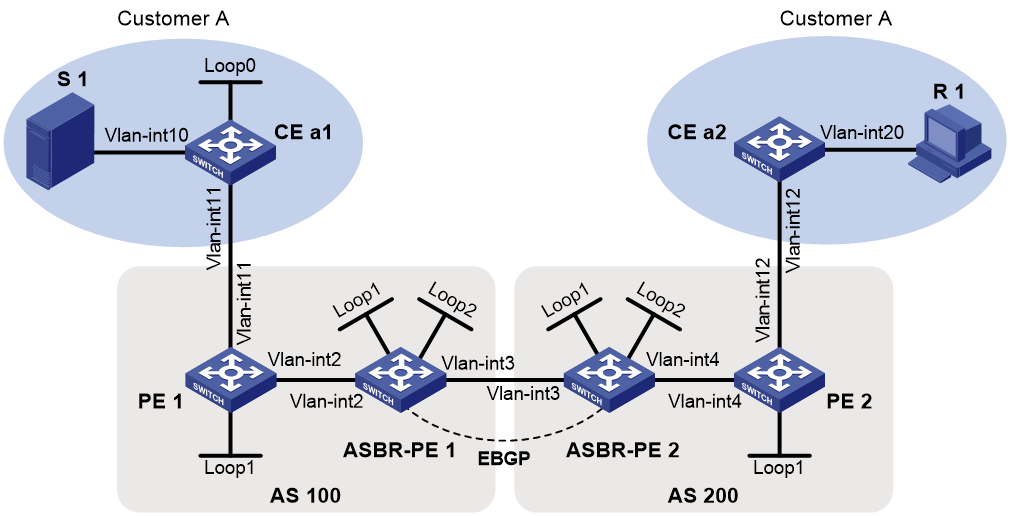
Table 2 Interface and IP address assignment
|
Device |
Interface |
IP address |
Device |
Interface |
IP address |
|
S 1 |
— |
10.11.3.2/24 |
R 1 |
— |
10.11.4.2/24 |
|
PE 1 |
Vlan-int2 |
192.168.1.2/24 |
ASBR-PE 2 |
Vlan-int4 |
192.168.3.2/24 |
|
PE 1 |
Vlan-int11 |
10.11.1.1/24 |
ASBR-PE 2 |
Vlan-int3 |
192.168.2.2/24 |
|
PE 1 |
Loop1 |
1.1.1.1/32 |
ASBR-PE 2 |
Loop1 |
1.1.1.3/32 |
|
ASBR-PE 1 |
Vlan-int2 |
192.168.1.1/24 |
ASBR-PE 2 |
Loop2 |
22.22.22.22/32 |
|
ASBR-PE 1 |
Vlan-int3 |
192.168.2.1/24 |
PE 2 |
Vlan-int4 |
192.168.3.1/24 |
|
ASBR-PE 1 |
Loop1 |
1.1.1.2/32 |
PE 2 |
Vlan-int12 |
10.11.2.1/24 |
|
ASBR-PE 1 |
Loop2 |
11.11.11.11/32 |
PE 2 |
Loop1 |
1.1.1.4/32 |
|
CE a1 |
Vlan-int10 |
10.11.3.1/24 |
CE a2 |
Vlan-int20 |
10.11.4.1/24 |
|
CE a1 |
Vlan-int11 |
10.11.1.2/24 |
CE a2 |
Vlan-int12 |
10.11.2.2/24 |
|
CE a1 |
Loopback 0 |
2.2.2.2/32 |
|
|
|
Analysis
To meet the network requirement, you must create a separate MDT-based MVPN for each AS.
Applicable hardware and software versions
The following matrix shows the hardware and software versions to which this configuration example is applicable:
|
Hardware |
Software version |
|
S6812 switch series S6813 switch series |
Not supported |
|
S6550XE-HI switch series |
Release 6008 and later, Release 8106Pxx |
|
S6525XE-HI switch series |
Release 6008 and later, Release 8106Pxx |
|
S5850 switch series |
Not supported |
|
S5570S-EI switch series |
Not supported |
|
S5560X-EI switch series |
Not supported |
|
S5560X-HI switch series |
Not supported |
|
S5500V2-EI switch series |
Not supported |
|
MS4520V2-30F switch |
Not supported |
|
MS4520V2-30C switch MS4520V2-54C switch |
Not supported |
|
MS4520V2-28S switch MS4520V2-24TP switch |
Not supported |
|
S6520X-HI switch series S6520X-EI switch series |
Not supported |
|
S6520X-SI switch series S6520-SI switch series |
Not supported |
|
S5000-EI switch series |
Not supported |
|
MS4600 switch series |
Not supported |
|
ES5500 switch series |
Not supported |
|
S5560S-EI switch series S5560S-SI switch series |
Not supported |
|
S5500V3-24P-SI S5500V3-48P-SI |
Not supported |
|
S5500V3-SI switch series (except S5500V3-24P-SI and S5500V3-48P-SI) |
Not supported |
|
S5170-EI switch series |
Not supported |
|
S5130S-HI switch series S5130S-EI switch series S5130S-SI switch series S5130S-LI switch series |
Not supported |
|
S5120V2-SI switch series S5120V2-LI switch series |
Not supported |
|
S5120V3-EI switch series |
Not supported |
|
S5120V3-36F-SI S5120V3-28P-HPWR-SI S5120V3-54P-PWR-SI |
Not supported |
|
S5120V3-SI switch series (except S5120V3-36F-SI, S5120V3-28P-HPWR-SI, and S5120V3-54P-PWR-SI) |
Not supported |
|
S5120V3-LI switch series |
Not supported |
|
S3600V3-EI switch series |
Not supported |
|
S3600V3-SI switch series |
Not supported |
|
S3100V3-EI switch series S3100V3-SI switch series |
Not supported |
|
S5110V2 switch series |
Not supported |
|
S5110V2-SI switch series |
Not supported |
|
S5000V3-EI switch series S5000V5-EI switch series |
Not supported |
|
S5000E-X switch series S5000X-EI switch series |
Not supported |
|
E128C switch E152C switch E500C switch series E500D switch series |
Not supported |
|
MS4320V2 switch series MS4320V3 switch series MS4300V2 switch series MS4320 switch series MS4200 switch series |
Not supported |
|
WS5850-WiNet switch series |
Not supported |
|
WS5820-WiNet switch series WS5810-WiNet switch series |
Not supported |
|
WAS6000 switch series |
Not supported |
|
IE4300-12P-AC switch IE4300-12P-PWR switch IE4300-M switch series IE4320 switch series |
Not supported |
Restrictions and guidelines
When you configure the inter-AS option A MDT-based MVPN, follow these restrictions and guidelines:
· You must enable the same PIM mode for all interfaces that belong to the same VPN instance (including the interface associated with the VPN instance). You may enable different PIM modes for the public network in different ASs.
· You must specify the same default-group for the same VPN instance in the same AS. You may specify different default-groups for the same VPN instance in different ASs.
Procedures
1. Assign an IP address and subnet mask to each interface on CE a1, as shown in Table 2.
<CEa1> system-view
[CEa1] interface vlan-interface 10
[CEa1-Vlan-interface10] ip address 10.11.3.1 24
[CEa1-Vlan-interface10] quit
[CEa1] interface loopback 0
[CEa1-LoopBack0] ip address 2.2.2.2 32
[CEa1-LoopBack0] quit
[CEa1] interface vlan-interface 11
[CEa1-Vlan-interface11] ip address 10.11.1.2 24
[CEa1-Vlan-interface11] quit
# Configure PE 1, ASBR-PE 1, ASBR-PE2, PE 2, and CE a2 in the same way CE a1 is configured. (Details not shown.)
2. Configure a unicast routing protocol and MPLS L3VPN inter-AS option A on all devices so that all devices in the ASs are interoperable at the network layer. (Details not shown)
For more information about configuring basic MPLS VPN, see MPLS Configuration Guide.
3. Enable IP multicast routing on the public network, and enable PIM-SM on the public network interfaces (including Loopback interfaces):
# On PE 1, enable IP multicast routing, and enable PIM-SM on the public network interfaces.
[PE1] multicast routing
[PE1-mrib] quit
[PE1] interface vlan-interface 2
[PE1-Vlan-interface2] pim sm
[PE1-Vlan-interface2] quit
[PE1] interface loopback 1
[PE1-LoopBack1] pim sm
[PE1-LoopBack1] quit
# On ASBR-PE 1, enable IP multicast routing, and enable PIM-SM on the public network interfaces.
[ASBR-PE1] multicast routing
[ASBR-PE1-mrib] quit
[ASBR-PE1] interface vlan-interface 2
[ASBR-PE1-Vlan-interface2] pim sm
[ASBR-PE1-Vlan-interface2] quit
[ASBR-PE1] interface loopback 1
[ASBR-PE1-LoopBack1] pim sm
[ASBR-PE1-LoopBack1] quit
[ASBR-PE1] interface loopback 2
[ASBR-PE1-LoopBack2] pim sm
[ASBR-PE1-LoopBack2] quit
# Configure Loopback 2 as a C-BSR and a C-RP.
[ASBR-PE1] pim
[ASBR-PE1-pim] c-bsr 11.11.11.11
[ASBR-PE1-pim] c-rp 11.11.11.11
[ASBR-PE1-pim] quit
# On PE 2, enable IP multicast routing, and enable PIM-SM on the public network interfaces.
[PE2] multicast routing
[PE2-mrib] quit
[PE2] interface vlan-interface 4
[PE2-Vlan-interface4] pim sm
[PE2-Vlan-interface4] quit
[PE2] interface loopback 1
[PE2-LoopBack1] pim sm
[PE2-LoopBack1] quit
# On ASBR-PE 2, enable IP multicast routing, and enable PIM-SM on the public network interfaces.
[ASBR-PE2] multicast routing
[ASBR-PE2-mrib] quit
[ASBR-PE2] interface vlan-interface 4
[ASBR-PE2-Vlan-interface4] pim sm
[ASBR-PE2-Vlan-interface4] quit
[ASBR-PE2] interface loopback 1
[ASBR-PE2-LoopBack1] pim sm
[ASBR-PE2-LoopBack1] quit
[ASBR-PE2] interface loopback 2
[ASBR-PE2-LoopBack2] pim sm
[ASBR-PE2-LoopBack2] quit
# Configure Loopback 2 as a C-BSR and a C-RP.
[ASBR-PE2] pim
[ASBR-PE2-pim] c-bsr 22.22.22.22
[ASBR-PE2-pim] c-rp 22.22.22.22
[ASBR-PE2-pim] quit
4. Enable IP multicast routing for the VPN instances, enable PIM-SM on the VPN instance interfaces, and enable IGMP on the interfaces that have receiver hosts attached:
|
|
NOTE: The route targets for the same VPN instance on the ASBRs and PEs within the same AS must match. Those within different ASs do not need to match. |
# On CE a1, enable IP multicast routing, enable PIM-SM on each interface.
[CEa1] multicast routing
[CEa1-mrib] quit
[CEa1] interface vlan-interface 10
[CEa1-Vlan-interface10] pim sm
[CEa1-Vlan-interface10] quit
[CEa1] interface vlan-interface 11
[CEa1-Vlan-interface11] pim sm
[CEa1-Vlan-interface11] quit
[CEa1] interface loopback 0
[CEa1-LoopBack0] pim sm
[CEa1-LoopBack0] quit
# Configure Loopback 0 as a C-BSR and a C-RP.
[CEa1] pim
[CEa1-pim] c-bsr 2.2.2.2
[CEa1-pim] c-rp 2.2.2.2
[CEa1-pim] quit
# On CE a2, enable IP multicast routing, enable PIM-SM on VLAN-interface 12, and enable IGMP on VLAN-interface 20.
[CEa2] multicast routing
[CEa2-mrib] quit
[CEa2] interface vlan-interface 12
[CEa2-Vlan-interface12] pim sm
[CEa2-Vlan-interface12] quit
[CEa2] interface vlan-interface 20
[CEa2-Vlan-interface20] igmp enable
[CEa2-Vlan-interface20] quit
# On PE 1, create a VPN instance named customerA.
[PE1] ip vpn-instance customerA
[PE1-vpn-instance-customerA] route-distinguisher 100:1
[PE1-vpn-instance-customerA] vpn-target 100:1 both
[PE1-vpn-instance-customerA] quit
# Associate VLAN-interface 11 with VPN instance customerA.
[PE1] interface vlan-interface 11
[PE1-Vlan-interface11] ip binding vpn-instance customerA
[PE1-Vlan-interface11] quit
# Enable IP multicast routing for VPN instance customerA, and enable PIM-SM on VLAN-interface 11.
[PE1] multicast routing vpn-instance customerA
[PE1-mrib-customerA] quit
[PE1] interface vlan-interface 11
[PE1-Vlan-interface11] pim sm
[PE1-Vlan-interface11] quit
# On PE 2, create a VPN instance named customerA.
[PE2] ip vpn-instance customerA
[PE2-vpn-instance-customerA] route-distinguisher 12:12
[PE2-vpn-instance-customerA] vpn-target 3:3 import-extcommunity
[PE2-vpn-instance-customerA] vpn-target 3:3 export-extcommunity
[PE2-vpn-instance] quit
# Associate VLAN-interface 12 with VPN instance customerA.
[PE2] interface vlan-interface 12
[PE2-Vlan-interface12] ip binding vpn-instance customerA
[PE2-Vlan-interface12] quit
# Enable IP multicast routing for VPN instance customerA, and enable PIM-SM on VLAN-interface 12.
[PE2] multicast routing vpn-instance customerA
[PE2-mrib-customerA] quit
[PE2] interface vlan-interface 12
[PE2-Vlan-interface12] pim sm
[PE2-Vlan-interface12] quit
# On ASBR-PE 1, create a VPN instance named customerA.
[ASBR-PE1] ip vpn-instance customerA
[ASBR-PE1-vpn-instance-customerA] route-distinguisher 100:1
[ASBR-PE1-vpn-instance-customerA] vpn-target 100:1 both
[ASBR-PE1-vpn-instance-customerA] quit
# Associate VLAN-interface 3 with VPN instance customerA.
[ASBR-PE1] interface vlan-interface 3
[ASBR-PE1-Vlan-interface3] ip binding vpn-instance customerA
[ASBR-PE1-Vlan-interface3] quit
# Enable IP multicast routing for VPN instance customerA, and enable PIM-SM on VLAN-interface 3.
[ASBR-PE1] multicast routing vpn-instance customerA
[ASBR-PE1-mrib-customerA] quit
[ASBR-PE1] interface vlan-interface 3
[ASBR-PE1-Vlan-interface3] pim sm
[ASBR-PE1-Vlan-interface3] quit
# On ASBR-PE 2, create a VPN instance named customerA.
[ASBR-PE2] ip vpn-instance customerA
[ASBR-PE2-vpn-vpn-customerA] route-distinguisher 200:1
[ASBR-PE2-vpn-vpn-customerA] vpn-target 200:1 both
[ASBR-PE2-vpn-vpn-customerA] quit
# Associate VLAN-interface 3 with VPN instance customerA.
[ASBR-PE2] interface vlan-interface 3
[ASBR-PE2-Vlan-interface3] ip binding vpn-instance customerA
[ASBR-PE2-Vlan-interface3] quit
# Enable IP multicast routing for VPN instance customerA, and enable PIM-SM on VLAN-interface 3.
[ASBR-PE2] multicast routing vpn-instance customerA
[ASBR-PE2-mrib-customerA] quit
[ASBR-PE2] interface vlan-interface 3
[ASBR-PE2-Vlan-interface3] pim sm
[ASBR-PE2-Vlan-interface3] quit
5. Configure the MDT-based MVPN for the VPN instance:
# On PE 1, create service loopback group 1 and specify the multicast tunnel service.
[PE1] service-loopback group 1 type multicast-tunnel
# Assign Ten-GigabitEthernet 1/0/4 to service loopback group 1.
[PE1] interface ten-gigabitethernet 1/0/4
[PE1-Ten-GigabitEthernet1/0/4] port service-loopback group 1
[PE1-Ten-GigabitEthernet1/0/4] quit
# Create an MDT-based MVPN for VPN instance customerA.
[PE1] multicast-vpn vpn-instance customerA mode mdt
# Create an MVPN IPv4 address family for VPN instance customerA.
[PE1-mvpn-customerA] address-family ipv4
# Specify the default group, MVPN source interface, and data group range for VPN instance customerA.
[PE1-mvpn-customerA-ipv4] default-group 239.1.1.1
[PE1-mvpn-customerA-ipv4] source loopback 1
[PE1-mvpn-customerA-ipv4] data-group 225.2.2.0 28
[PE1-mvpn-customerA-ipv4] quit
[PE1-mvpn-customerA] quit
# On ASBR-PE 1, create service loopback group 1 and specify the multicast tunnel service.
[ASBR-PE1] service-loopback group 1 type multicast-tunnel
# Assign Ten-GigabitEthernet 1/0/4 to service loopback group 1.
[ASBR-PE1] interface ten-gigabitethernet 1/0/4
[ASBR-PE1-Ten-GigabitEthernet1/0/4] port service-loopback group 1
[ASBR-PE1-Ten-GigabitEthernet1/0/4] quit
# Create an MDT-based MVPN for VPN instance customerA.
[ASBR-PE1] multicast-vpn vpn-instance customerA mode mdt
# Create an MVPN IPv4 address family for VPN instance customerA.
[ASBR-PE1-mvpn-customerA] address-family ipv4
# Specify the default group, MVPN source interface, and data group range for VPN instance customerA.
[ASBR-PE1-mvpn-customerA-ipv4] default-group 239.1.1.1
[ASBR-PE1-mvpn-customerA-ipv4] source loopback 1
[ASBR-PE1-mvpn-customerA-ipv4] data-group 225.2.2.0 28
[ASBR-PE1-mvpn-customerA-ipv4] quit
[ASBR-PE1-mvpn-customerA] quit
# On PE 2, create service loopback group 1 and specify the multicast tunnel service.
[PE2] service-loopback group 1 type multicast-tunnel
# Assign Ten-GigabitEthernet 1/0/4 to service loopback group 1.
[PE2] interface ten-gigabitethernet 1/0/4
[PE2-Ten-GigabitEthernet1/0/4] port service-loopback group 1
[PE2-Ten-GigabitEthernet1/0/4] quit
# Create an MDT-based MVPN for VPN instance customerA.
[PE2] multicast-vpn vpn-instance customerA mode mdt
# Create an MVPN IPv4 address family for VPN instance customerA.
[PE2-mvpn-customerA] address-family ipv4
# Specify the default group, MVPN source interface, and data group range for VPN instance customerA.
[PE2-mvpn-customerA-ipv4] default-group 239.1.1.1
[PE2-mvpn-customerA-ipv4] source loopback 1
[PE2-mvpn-customerA-ipv4] data-group 225.2.2.0 28
[PE2-mvpn-customerA-ipv4] quit
[PE2-mvpn-customerA] quit
# On ASBR-PE 2, create service loopback group 1 and specify the multicast tunnel service.
[ASBR-PE2] service-loopback group 1 type multicast-tunnel
# Assign Ten-GigabitEthernet 1/0/4 to service loopback group 1.
[ASBR-PE2] interface ten-gigabitethernet 1/0/4
[ASBR-PE2-Ten-GigabitEthernet1/0/4] port service-loopback group 1
[ASBR-PE2-Ten-GigabitEthernet1/0/4] quit
# Create an MDT-based MVPN for VPN instance customerA.
[ASBR-PE2] multicast-vpn vpn-instance customerA mode mdt
# Create an MVPN IPv4 address family for VPN instance customerA.
[ASBR-PE2-mvpn-customerA] address-family ipv4
# Specify the default group, MVPN source interface, and data group range for VPN instance customerA.
[ASBR-PE2-mvpn-customerA-ipv4] default-group 239.1.1.1
[ASBR-PE2-mvpn-customerA-ipv4] source loopback 1
[ASBR-PE2-mvpn-customerA-ipv4] data-group 225.2.2.0 28
[ASBR-PE2-mvpn-customerA-ipv4] quit
[ASBR-PE2-mvpn-customerA] quit
Verifying the configuration
# Verify that the default-MDT has been established on the public network in each AS on PEs and ASBR-PEs. The following example shows PIM routing table for the public network on ASBR-PE 1.
[ASBR-PE1]display pim routing-table
Total 1 (*, G) entries; 1 (S, G) entries
(*, 239.1.1.1)
RP: 11.11.11.11 (local)
Protocol: pim-sm, Flag: SPT LOC ACT
UpTime: 02:54:43
Upstream interface: Register
Upstream neighbor: NULL
RPF prime neighbor: NULL
Downstream interface(s) information:
Total number of downstreams: 1
1: Vlan-interface2
Protocol: pim-sm, UpTime: 02:54:43, Expires: -
(1.1.1.1, 239.1.1.1)
RP: 11.11.11.11 (local)
Protocol: pim-sm, Flag: SPT LOC ACT
UpTime: 01:57:13
Upstream interface: Vlan-interface2
Upstream neighbor: 192.168.1.2
RPF prime neighbor: 192.168.1.2
Downstream interface(s) information: None
The output shows that an RPT for (*, 239.1.1.1) and an SPT for (1.1.1.1, 239.1.1.1) have been established on the public network. The RPT and SPT constitute the default-MDT for the public network.
Configuration files
· PE 1:
#
ip vpn-instance customerA
route-distinguisher 100:1
vpn-target 100:1 import-extcommunity
vpn-target 100:1 export-extcommunity
#
service-loopback group 1 type multicast-tunnel
#
vlan 2
#
vlan 11
#
interface LoopBack1
ip address 1.1.1.1 255.255.255.255
pim sm
#
interface Vlan-interface2
ip address 192.168.1.2 255.255.255.0
pim sm
#
interface Vlan-interface11
ip binding vpn-instance customerA
ip address 10.11.1.1 255.255.255.0
pim sm
#
interface Ten-GigabitEthernet1/0/4
port link-mode bridge
port service-loopback group 1
#
multicast routing
#
multicast routing vpn-instance customerA
#
multicast-vpn vpn-instance customerA mode mdt
address-family ipv4
source LoopBack1
default-group 239.1.1.1
data-group 225.2.2.0 255.255.255.240
#
· PE 2:
#
ip vpn-instance customerA
route-distinguisher 200:2
vpn-target 200:2 import-extcommunity
vpn-target 200:2 export-extcommunity
#
service-loopback group 1 type multicast-tunnel
#
vlan 4
#
vlan 12
#
interface LoopBack1
ip address 1.1.1.4 255.255.255.255
pim sm
#
interface Vlan-interface4
ip address 192.168.3.1 255.255.255.0
pim sm
#
interface Vlan-interface12
ip binding vpn-instance customerA
ip address 10.11.2.1 255.255.255.0
pim sm
#
interface Ten-GigabitEthernet1/0/4
port link-mode bridge
port service-loopback group 1
#
multicast routing
#
multicast routing vpn-instance customerA
#
multicast-vpn vpn-instance customerA mode mdt
address-family ipv4
source LoopBack1
default-group 239.1.1.1
data-group 225.2.2.0 255.255.255.240
#
· ASBR-PE 1:
#
ip vpn-instance customerA
route-distinguisher 100:1
vpn-target 100:1 import-extcommunity
vpn-target 100:1 export-extcommunity
#
service-loopback group 1 type multicast-tunnel
#
vlan 2 to 3
#
interface LoopBack1
ip address 1.1.1.2 255.255.255.255
pim sm
#
interface LoopBack2
ip address 11.11.11.11 255.255.255.255
pim sm
#
interface Vlan-interface2
ip address 192.168.1.1 255.255.255.0
pim sm
#
interface Vlan-interface3
ip binding vpn-instance customerA
ip address 192.168.2.1 255.255.255.0
pim sm
#
interface Ten-GigabitEthernet1/0/4
port link-mode bridge
port service-loopback group 1
#
multicast routing
#
multicast routing vpn-instance customerA
#
pim
c-bsr 11.11.11.11
c-rp 11.11.11.11
#
multicast-vpn vpn-instance customerA mode mdt
address-family ipv4
source LoopBack1
default-group 239.1.1.1
data-group 225.2.2.0 255.255.255.240
#
· ASBR-PE 2:
#
ip vpn-instance customerA
route-distinguisher 200:1
vpn-target 200:1 import-extcommunity
vpn-target 200:1 export-extcommunity
#
service-loopback group 1 type multicast-tunnel
#
vlan 3 to 4
#
interface LoopBack1
ip address 1.1.1.3 255.255.255.255
pim sm
#
interface LoopBack2
ip address 22.22.22.22 255.255.255.255
pim sm
#
interface Vlan-interface3
ip binding vpn-instance customerA
ip address 192.168.2.2 255.255.255.0
pim sm
#
interface Vlan-interface4
ip address 192.168.3.2 255.255.255.0
pim sm
#
interface Ten-GigabitEthernet1/0/4
port link-mode bridge
port service-loopback group 1
#
multicast routing
#
multicast routing vpn-instance customerA
#
pim
c-bsr 22.22.22.22
c-rp 22.22.22.22
#
multicast-vpn vpn-instance customerA mode mdt
address-family ipv4
source LoopBack1
default-group 239.1.1.1
data-group 225.2.2.0 255.255.255.240
#
· CE a1:
#
vlan 10 to 11
#
interface LoopBack0
ip address 2.2.2.2 255.255.255.255
pim sm
#
interface Vlan-interface10
ip address 10.11.3.1 255.255.255.0
pim sm
#
interface Vlan-interface11
ip address 10.11.1.2 255.255.255.0
pim sm
#
multicast routing
#
pim
c-bsr 2.2.2.2
c-rp 2.2.2.2
#
· CE a2:
#
vlan 12
#
vlan 20
#
interface Vlan-interface12
ip address 10.11.2.2 255.255.255.0
pim sm
#
interface Vlan-interface20
ip address 10.11.4.1 255.255.255.0
igmp enable
#
multicast routing
#
Example: Configuring inter-AS option C MDT-based MVPN
Network configuration
As shown in Figure 3:
· Customer A has two branches that separately connect to AS 100 and AS 200.
· ASBR-PE 1 and ASBR-PE 2 are interconnected by using the inter-AS option C solution.
· PIM-SM runs within the two branches.
· The multicast source and the receiver host are in different branches.
Configure inter-AS option C MDT-based MVPN so that the receiver host can receive the multicast data from the source.
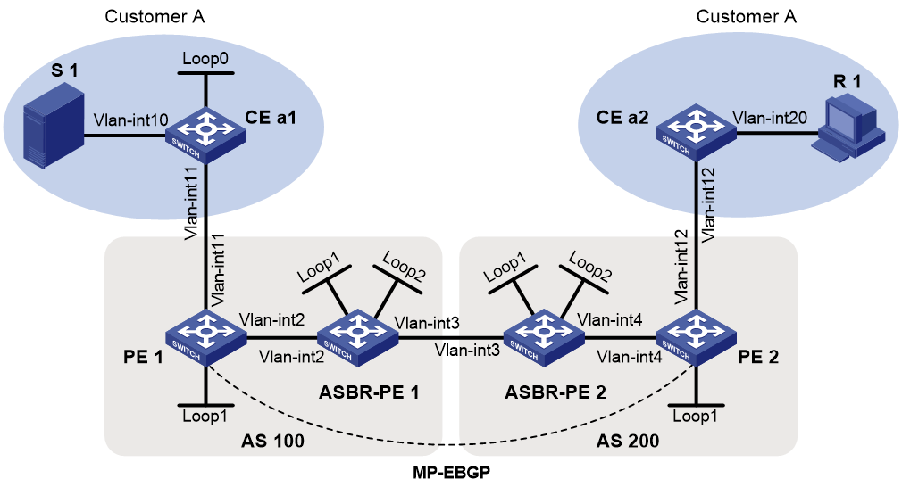
Table 3 Interface and IP address assignment
|
Device |
Interface |
IP address |
Device |
Interface |
IP address |
|
S 1 |
— |
10.11.3.2/24 |
R 1 |
— |
10.11.4.2/24 |
|
PE 1 |
Vlan-int2 |
192.168.1.2/24 |
ASBR-PE2 |
Vlan-int4 |
192.168.3.2/24 |
|
PE 1 |
Vlan-int11 |
10.11.1.1/24 |
ASBR-PE2 |
Vlan-int3 |
192.168.2.2/24 |
|
PE 1 |
Loop1 |
1.1.1.1/32 |
ASBR-PE2 |
Loop1 |
1.1.1.3/32 |
|
ASBR-PE1 |
Vlan-int2 |
192.168.1.1/24 |
ASBR-PE2 |
Loop2 |
22.22.22.22/32 |
|
ASBR-PE1 |
Vlan-int3 |
192.168.2.1/24 |
PE 2 |
Vlan-int4 |
192.168.3.1/24 |
|
ASBR-PE1 |
Loop1 |
1.1.1.2/32 |
PE 2 |
Vlan-int12 |
10.11.2.1/24 |
|
ASBR-PE1 |
Loop2 |
11.11.11.11/32 |
PE 2 |
Loop1 |
1.1.1.4/32 |
|
CE a1 |
Vlan-int10 |
10.11.3.1/24 |
CE a2 |
Vlan-int20 |
10.11.4.1/24 |
|
CE a1 |
Vlan-int11 |
10.11.1.2/24 |
CE a2 |
Vlan-int12 |
10.11.2.2/24 |
|
CE a1 |
Loop0 |
2.2.2.2/32 |
|
|
|
Analysis
To meet the network requirement, you must perform the following tasks:
· Create the same MDT-based MVPN for each AS.
· Establish MSDP peering relationships between the RPs in the ASs to share the multicast source information in different PIM-SM domains.
Applicable hardware and software versions
The following matrix shows the hardware and software versions to which this configuration example is applicable:
|
Hardware |
Software version |
|
S6812 switch series S6813 switch series |
Not supported |
|
S6550XE-HI switch series |
Release 6008 and later, Release 8106Pxx |
|
S6525XE-HI switch series |
Release 6008 and later, Release 8106Pxx |
|
S5850 switch series |
Not supported |
|
S5570S-EI switch series |
Not supported |
|
S5560X-EI switch series |
Not supported |
|
S5560X-HI switch series |
Not supported |
|
S5500V2-EI switch series |
Not supported |
|
MS4520V2-30F switch |
Not supported |
|
MS4520V2-30C switch MS4520V2-54C switch |
Not supported |
|
MS4520V2-28S switch MS4520V2-24TP switch |
Not supported |
|
S6520X-HI switch series S6520X-EI switch series |
Not supported |
|
S6520X-SI switch series S6520-SI switch series |
Not supported |
|
S5000-EI switch series |
Not supported |
|
MS4600 switch series |
Not supported |
|
ES5500 switch series |
Not supported |
|
S5560S-EI switch series S5560S-SI switch series |
Not supported |
|
S5500V3-24P-SI S5500V3-48P-SI |
Not supported |
|
S5500V3-SI switch series (except S5500V3-24P-SI and S5500V3-48P-SI) |
Not supported |
|
S5170-EI switch series |
Not supported |
|
S5130S-HI switch series S5130S-EI switch series S5130S-SI switch series S5130S-LI switch series |
Not supported |
|
S5120V2-SI switch series S5120V2-LI switch series |
Not supported |
|
S5120V3-EI switch series |
Not supported |
|
S5120V3-36F-SI S5120V3-28P-HPWR-SI S5120V3-54P-PWR-SI |
Not supported |
|
S5120V3-SI switch series (except S5120V3-36F-SI, S5120V3-28P-HPWR-SI, and S5120V3-54P-PWR-SI) |
Not supported |
|
S5120V3-LI switch series |
Not supported |
|
S3600V3-EI switch series |
Not supported |
|
S3600V3-SI switch series |
Not supported |
|
S3100V3-EI switch series S3100V3-SI switch series |
Not supported |
|
S5110V2 switch series |
Not supported |
|
S5110V2-SI switch series |
Not supported |
|
S5000V3-EI switch series S5000V5-EI switch series |
Not supported |
|
S5000E-X switch series S5000X-EI switch series |
Not supported |
|
E128C switch E152C switch E500C switch series E500D switch series |
Not supported |
|
MS4320V2 switch series MS4320V3 switch series MS4300V2 switch series MS4320 switch series MS4200 switch series |
Not supported |
|
WS5850-WiNet switch series |
Not supported |
|
WS5820-WiNet switch series WS5810-WiNet switch series |
Not supported |
|
WAS6000 switch series |
Not supported |
|
IE4300-12P-AC switch IE4300-12P-PWR switch IE4300-M switch series IE4320 switch series |
Not supported |
Procedures
1. Assign an IP address and subnet mask to each interface on CE a1, as shown in Table 3.
<CEa1> system-view
[CEa1] interface vlan-interface 10
[CEa1-Vlan-interface10] ip address 10.11.3.1 24
[CEa1-Vlan-interface10] quit
[CEa1] interface loopback 0
[CEa1-LoopBack0] ip address 2.2.2.2 32
[CEa1-LoopBack0] quit
[CEa1] interface vlan-interface 11
[CEa1-Vlan-interface11] ip address 10.11.1.2 24
[CEa1-Vlan-interface11] quit
# Configure PE 1, ASBR-PE 1, ASBR-PE 2, PE 2, and CE a2 in the same way CE a1 is configured. (Details not shown.)
2. Configure a unicast routing protocol and basic MPLS VPN on all devices so that all devices are interoperable at the network layer. (Details not shown)
For more information about configuring basic MPLS VPN, see MPLS Configuration Guide.
3. Enable IP multicast routing on the public network in each AS, enable PIM-SM on the public network interfaces (including Loopback interfaces), and configure PIM-SM domain boarders:
# On PE 1, enable IP multicast routing, and enable PIM-SM on the public network interfaces.
[PE1] multicast routing
[PE1-mrib] quit
[PE1] interface vlan-interface 2
[PE1-Vlan-interface2] pim sm
[PE1-Vlan-interface2] quit
[PE1] interface loopback 1
[PE1-LoopBack1] pim sm
[PE1-LoopBack1] quit
# On ASBR-PE 1, enable IP multicast routing, and enable PIM-SM on the public network interfaces.
[ASBR-PE1] multicast routing
[ASBR-PE1-mrib] quit
[ASBR-PE1] interface vlan-interface 2
[ASBR-PE1-Vlan-interface2] pim sm
[ASBR-PE1-Vlan-interface2] quit
[ASBR-PE1] interface vlan-interface 3
[ASBR-PE1-Vlan-interface3] pim sm
[ASBR-PE1-Vlan-interface3] quit
[ASBR-PE1] interface loopback 1
[ASBR-PE1-LoopBack1] pim sm
[ASBR-PE1-LoopBack1] quit
[ASBR-PE1] interface loopback 2
[ASBR-PE1-LoopBack2] pim sm
[ASBR-PE1-LoopBack2] quit
# Configure Loopback 2 as a C-BSR and a C-RP.
[ASBR-PE1] pim
[ASBR-PE1-pim] c-bsr 11.11.11.11
[ASBR-PE1-pim] c-rp 11.11.11.11
[ASBR-PE1-pim] quit
# Configure VLAN-interface 3 as a PIM-SM domain boarder.
[ASBR-PE1] interface vlan-interface 3
[ASBR-PE1-Vlan-interface3] pim bsr-boundary
[ASBR-PE1-Vlan-interface3] quit
# On PE 2, enable IP multicast routing, and enable PIM-SM on the public network interfaces.
[PE2] multicast routing
[PE2-mrib] quit
[PE2] interface vlan-interface 4
[PE2-Vlan-interface4] pim sm
[PE2-Vlan-interface4] quit
[PE2] interface loopback 1
[PE2-LoopBack1] pim sm
[PE2-LoopBack1] quit
# On ASBR-PE 2, enable IP multicast routing, and enable PIM-SM on the public network interfaces.
[ASBR-PE2] multicast routing
[ASBR-PE2-mrib] quit
[ASBR-PE2] interface vlan-interface 3
[ASBR-PE2-Vlan-interface3] pim sm
[ASBR-PE2-Vlan-interface3] quit
[ASBR-PE2] interface vlan-interface 4
[ASBR-PE2-Vlan-interface4] pim sm
[ASBR-PE2-Vlan-interface4] quit
[ASBR-PE2] interface loopback 1
[ASBR-PE2-LoopBack1] pim sm
[ASBR-PE2-LoopBack1] quit
[ASBR-PE2] interface loopback 2
[ASBR-PE2-LoopBack2] pim sm
[ASBR-PE2-LoopBack2] quit
# Configure Loopback 2 as a C-BSR and a C-RP.
[ASBR-PE2] pim
[ASBR-PE2-pim] c-bsr 22.22.22.22
[ASBR-PE2-pim] c-rp 22.22.22.22
[ASBR-PE2-pim] quit
# Configure VLAN-interface 3 as a PIM-SM domain boarder.
[ASBR-PE2] interface vlan-interface 3
[ASBR-PE2-Vlan-interface3] pim bsr-boundary
[ASBR-PE2-Vlan-interface3] quit
4. Establish MSDP peering relationships between the RPs on the public network in the ASs:
# On ASBR-PE 1, specify an MSDP peer.
[ASBR-PE1] msdp
[ASBR-PE1-msdp] encap-data-enable
[ASBR-PE1-msdp] peer 192.168.2.2 connect-interface vlan-interface 3
# On ASBR-PE 2, specify an MSDP peer.
[ASBR-PE2] msdp
[ASBR-PE2-msdp] encap-data-enable
[ASBR-PE2-msdp] peer 192.168.2.1 connect-interface vlan-interface 3
5. Enable IP multicast routing for the VPN instance, enable PIM-SM on the private network interfaces, and enable IGMP on the interfaces that have receiver hosts attached:
|
|
NOTE: The route targets for the same VPN instance on the ASBRs and PEs within the same AS must match. Those within different ASs do not need to match. |
# On CE a1, enable IP multicast routing, and enable PIM-SM on each interface.
[CEa1] multicast routing
[CEa1-mrib] quit
[CEa1] interface vlan-interface 10
[CEa1-Vlan-interface10] pim sm
[CEa1-Vlan-interface10] quit
[CEa1] interface vlan-interface 11
[CEa1-Vlan-interface11] pim sm
[CEa1-Vlan-interface11] quit
[CEa1] interface loopback 0
[CEa1-LoopBack0] pim sm
[CEa1-LoopBack0] quit
# Configure Loopback 0 as a C-BSR and a C-RP.
[CEa1] pim
[CEa1-pim] c-bsr 2.2.2.2
[CEa1-pim] c-rp 2.2.2.2
[CEa1-pim] quit
# On CE a2, enable IP multicast routing, enable PIM-SM on VLAN-interface 12, and enable IGMP on VLAN-interface 20.
[CEa2] multicast routing
[CEa2-mrib] quit
[CEa2] interface vlan-interface 12
[CEa2-Vlan-interface12] pim sm
[CEa2-Vlan-interface12] quit
[CEa2] interface vlan-interface 20
[CEa2-Vlan-interface20] igmp enable
[CEa2-Vlan-interface20] quit
# On PE 1, create a VPN instance named customerA.
[PE1] ip vpn-instance customerA
[PE1-vpn-instance-customerA] route-distinguisher 11:11
[PE1-vpn-instance-customerA] vpn-target 3:3 import-extcommunity
[PE1-vpn-instance-customerA] vpn-target 3:3 export-extcommunity
[PE1-vpn-instance-customerA] quit
# Associate VLAN-interface 11 with VPN instance customerA.
[PE1] interface vlan-interface 11
[PE1-Vlan-interface11] ip binding vpn-instance customerA
[PE1-Vlan-interface11] quit
# Enable IP multicast routing for VPN instance customerA, and enable PIM-SM on VLAN-interface 11.
[PE1] multicast routing vpn-instance customerA
[PE1-mrib-customerA] quit
[PE1] interface vlan-interface 11
[PE1-Vlan-interface11] pim sm
[PE1-Vlan-interface11] quit
# On PE 2, create a VPN instance named customerA.
[PE2] ip vpn-instance customerA
[PE2-vpn-instance-customerA] route-distinguisher 12:12
[PE2-vpn-instance-customerA] vpn-target 3:3 import-extcommunity
[PE2-vpn-instance-customerA] vpn-target 3:3 export-extcommunity
[PE2-vpn-instance] quit
# Associate VLAN-interface 12 with VPN instance customerA.
[PE2] interface vlan-interface 12
[PE2-Vlan-interface12] ip binding vpn-instance customerA
[PE2-Vlan-interface12] quit
# Enable IP multicast routing for VPN instance customerA, and enable PIM-SM on VLAN-interface 12.
[PE2] multicast routing vpn-instance customerA
[PE2-mrib-customerA] quit
[PE2] interface vlan-interface 12
[PE2-Vlan-interface12] pim sm
[PE2-Vlan-interface12] quit
6. Create the same MDT-based MVPN for the ASs, and specify the default-group, MVPN source interface, and data-group for the MVPN:
# On PE 1, create service loopback group 1 and specify the multicast tunnel service.
[PE1] service-loopback group 1 type multicast-tunnel
# Assign Ten-GigabitEthernet 1/0/4 to service loopback group 1.
[PE1] interface ten-gigabitethernet 1/0/4
[PE1-Ten-GigabitEthernet1/0/4] port service-loopback group 1
[PE1-Ten-GigabitEthernet1/0/4] quit
# Create an MDT-based MVPN for VPN instance customerA.
[PE1] multicast-vpn vpn-instance customerA mode mdt
# Create an MVPN IPv4 address family for VPN instance customerA.
[PE1-mvpn-customerA] address-family ipv4
# Specify the default group, MVPN source interface, and data group range for VPN instance customerA.
[PE1-mvpn-customerA-ipv4] default-group 239.1.1.1
[PE1-mvpn-customerA-ipv4] source loopback 1
[PE1-mvpn-customerA-ipv4] data-group 225.2.2.0 28
[PE2-mvpn-customerA-ipv4] quit
[PE1-mvpn-customerA] quit
# On PE 2, create service loopback group 1 and specify the multicast tunnel service.
[PE2] service-loopback group 1 type multicast-tunnel
# Assign Ten-GigabitEthernet 1/0/4 to service loopback group 1.
[PE2] interface ten-gigabitethernet 1/0/4
[PE2-Ten-GigabitEthernet1/0/4] port service-loopback group 1
[PE2-Ten-GigabitEthernet1/0/4] quit
# Create an MDT-based MVPN for VPN instance customerA.
[PE2] multicast-vpn vpn-instance customerA mode mdt
# Create an MVPN IPv4 address family for VPN instance customerA.
[PE2-mvpn-customerA] address-family ipv4
# Specify the default group, MVPN source interface, and data group range for VPN instance customerA.
[PE2-mvpn-customerA-ipv4] default-group 239.1.1.1
[PE2-mvpn-customerA-ipv4] source loopback 1
[PE2-mvpn-customerA-ipv4] data-group 225.2.2.0 28
[PE2-mvpn-customerA-ipv4] quit
[PE2-mvpn-customerA] quit
Verifying the configuration
# Verify that the default-MDT has been established on the public network in each AS on PEs and ASBR-PEs. The following example shows PIM routing table for the public network on ASBR-PE 1.
[ASBR-PE1]display pim routing-table
Total 1 (*, G) entries; 2 (S, G) entries
(*, 239.1.1.1)
RP: 3.3.3.3 (local)
Protocol: pim-sm, Flag: SPT LOC ACT
UpTime: 02:54:43
Upstream interface: Register
Upstream neighbor: NULL
RPF prime neighbor: NULL
Downstream interface(s) information:
Total number of downstreams: 1
1: Vlan-interface2
Protocol: pim-sm, UpTime: 02:54:43, Expires: -
(1.1.1.1, 239.1.1.1)
RP: 3.3.3.3 (local)
Protocol: pim-sm, Flag: SPT LOC ACT
UpTime: 01:57:13
Upstream interface: Vlan-interface2
Upstream neighbor: 192.168.1.2
RPF prime neighbor: 192.168.1.2
Downstream interface(s) information: None
(1.1.1.4, 239.1.1.1)
RP: 3.3.3.3 (local)
Protocol: pim-sm, Flag: SPT LOC ACT
UpTime: 01:57:13
Upstream interface: Vlan-interface3
Upstream neighbor: 192.168.2.2
RPF prime neighbor: 192.168.2.2
Downstream interface(s) information: None
The output shows that an RPT for (*, 239.1.1.1), an SPT for (1.1.1.1, 239.1.1.1), and an SPT for (1.1.1.4, 239.1.1.1) have been established on the public network. The RPT and SPTs constitute the default-MDT for the public network.
Configuration files
· PE 1:
#
ip vpn-instance customerA
route-distinguisher 11:11
vpn-target 3:3 import-extcommunity
vpn-target 3:3 export-extcommunity
#
service-loopback group 1 type multicast-tunnel
#
vlan 2
#
vlan 11
#
interface LoopBack1
ip address 1.1.1.1 255.255.255.255
pim sm
#
interface Vlan-interface2
ip address 192.168.1.2 255.255.255.0
pim sm
#
interface Vlan-interface11
ip binding vpn-instance customerA
ip address 10.11.1.1 255.255.255.0
pim sm
#
interface Ten-GigabitEthernet1/0/4
port link-mode bridge
port service-loopback group 1
#
multicast routing
#
multicast routing vpn-instance customerA
#
multicast-vpn vpn-instance customerA mode mdt
address-family ipv4
source LoopBack1
default-group 239.1.1.1
data-group 225.2.2.0 255.255.255.240
#
· PE 2:
#
ip vpn-instance customerA
route-distinguisher 12:12
vpn-target 3:3 import-extcommunity
vpn-target 3:3 export-extcommunity
#
service-loopback group 1 type multicast-tunnel
#
vlan 4
#
vlan 12
#
interface LoopBack1
ip address 1.1.1.4 255.255.255.255
pim sm
#
interface Vlan-interface4
ip address 192.168.3.1 255.255.255.0
pim sm
#
interface Vlan-interface12
ip binding vpn-instance customerA
ip address 10.11.2.1 255.255.255.0
pim sm
#
interface Ten-GigabitEthernet1/0/4
port link-mode bridge
port service-loopback group 1
#
multicast routing
#
multicast routing vpn-instance customerA
#
multicast-vpn vpn-instance customerA mode mdt
address-family ipv4
source LoopBack1
default-group 239.1.1.1
data-group 225.2.2.0 255.255.255.240
#
· ASBR-PE 1:
#
vlan 2 to 3
#
interface LoopBack1
ip address 1.1.1.2 255.255.255.255
pim sm
#
interface LoopBack2
ip address 11.11.11.11 255.255.255.255
pim sm
#
interface Vlan-interface2
ip address 192.168.1.1 255.255.255.0
pim sm
#
interface Vlan-interface3
ip address 192.168.2.1 255.255.255.0
pim sm
pim bsr-boundary
#
multicast routing
#
pim
c-bsr 11.11.11.11
c-rp 11.11.11.11
#
msdp
encap-data-enable
peer 192.168.2.2 connect-interface Vlan-interface3
#
· ASBR-PE 2:
#
vlan 3 to 4
#
interface LoopBack1
ip address 1.1.1.3 255.255.255.255
pim sm
#
interface LoopBack2
ip address 22.22.22.22 255.255.255.255
pim sm
#
interface Vlan-interface3
ip address 192.168.2.2 255.255.255.0
pim sm
pim bsr-boundary
#
interface Vlan-interface4
ip address 192.168.3.2 255.255.255.0
pim sm
#
multicast routing
#
pim
c-bsr 22.22.22.22
c-rp 22.22.22.22
#
msdp
encap-data-enable
peer 192.168.2.1 connect-interface Vlan-interface3
#
· CE a1:
#
vlan 10 to 11
#
interface LoopBack0
ip address 2.2.2.2 255.255.255.255
pim sm
#
interface Vlan-interface10
ip address 10.11.3.1 255.255.255.0
pim sm
#
interface Vlan-interface11
ip address 10.11.1.2 255.255.255.0
pim sm
#
multicast routing
#
pim
c-bsr 2.2.2.2
c-rp 2.2.2.2
#
· CE a2:
#
vlan 12
#
vlan 20
#
interface Vlan-interface12
ip address 10.11.2.2 255.255.255.0
pim sm
#
interface Vlan-interface20
ip address 10.11.4.1 255.255.255.0
igmp enable
#
multicast routing
#
