- Table of Contents
-
- H3C Low-End Ethernet Switches Configuration Guide(V1.01)
- 01-Login Configuration Guide
- 02-VLAN Configuration Guide
- 03-IP Address Configuration Guide
- 04-Voice VLAN Configuration Guide
- 05-GVRP Configuration Guide
- 06-Ethernet Interface Basic Configuration Guide
- 07-Link Aggregation Configuration Guide
- 08-Port Isolation Configuration Guide
- 09-Port Security Configuration Guide
- 10-Port Binding Configuration Guide
- 11-MAC Address Table Management Configuration Guide
- 12-DLDP Configuration Guide
- 13-Auto Detect Configuration Guide
- 14-MSTP Configuration Guide
- 15-Routing Configuration Guide
- 16-Multicast Configuration Guide
- 17-802.1x Configuration Guide
- 18-AAA Configuration Guide
- 19-MAC Authentication Configuration Guide
- 20-VRRP Configuration Guide
- 21-ARP Configuration Guide
- 22-DHCP Configuration Guide
- 23-ACL Configuration Guide
- 24-QoS-QoS Profile Configuration Guide
- 25-Web Cache Redirection Configuration Guide
- 26-Mirroring Configuration Guide
- 27-IRF Configuration Guide
- 28-Cluster Configuration Guide
- 29-PoE-PoE Profile Configuration Guide
- 30-UDP Helper Configuration Guide
- 31-SNMP-RMON Configuration Guide
- 32-NTP Configuration Guide
- 33-SSH Configuration Guide
- 34-FTP and TFTP Configuration Guide
- 35-Information Center Configuration Guide
- 36-VLAN-VPN Configuration Guide
- 37-HWPing Configuration Guide
- 38-DNS Configuration Guide
- 39-Access Management Configuration Guide
- 40-Web Authentication Configuration Guide
- 41-IPv6 Management Configuration Guide
- 42-Smart link - Monitor Link Configuration Guide
- 43-VLAN Mapping Configuration Guide
- Related Documents
-
| Title | Size | Download |
|---|---|---|
| 43-VLAN Mapping Configuration Guide | 97.53 KB |
1 VLAN Mapping Configuration Guide·
Networking and Configuration Requirements
Configuration Example (Using ACLs for Traffic Classification)
Configuration Example (Configuring VLAN Mapping Rules Manually)
Configuring VLAN Mapping
Network Diagram
Figure 1-1 Network diagram for configuring VLAN Mapping
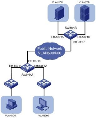
Networking and Configuration Requirements
Two customer networks are connected to the public network through Switch A and Switch B. Configure the VLAN mapping function to enable packets to be exchanged between the two networks through the public network VLANs.
l Switch A provides network access for terminal devices in VLAN 100 and VLAN 200 through Ethernet 1/0/11 and Ethernet 1/0/12. On the other side of the public network, Switch B provides network access for servers in VLAN 100 and VLAN 200 through Ethernet 1/0/15 and Ethernet 1/0/16.
l Ethernet 1/0/10 of Switch A connects the customer network to the public network, and so does Ethernet 1/0/17 of Switch B.
l It is required that packets of VLAN 100 and the packets of VLAN 200 of the two customer networks are transmitted in the public network carrying the tag of VLAN 500 and the tag of VLAN 600.
Applicable Product Matrix
On different low-end series Ethernet switches, VLAN mapping may be implemented in different ways. VLAN mapping may be implemented in one of the following two ways:
Using ACLs for traffic classification
Use ACLs to match packets carrying the specified VLAN ID and then map the VLAN ID to the specified VLAN ID. You can configure VLAN mapping on a switch connecting the customer network to the service provider network. VLAN mapping can satisfy the service provider network’s planning requirements by mapping the specified customer VLAN ID to the specified service VLAN ID.
|
Product series |
Software version |
Hardware version |
|
S5600 series |
Release 1510, Release 1602 |
All versions |
|
S5100-EI series |
Release 2200, Release 2201 |
All versions |
|
S3600-SI/EI series |
Release 1510, Release 1602 |
All versions |
|
S3100-52P |
Release 1500, Release 1602 |
S3100-52P |
Configuring VLAN mapping rules manually
Another approach to VLAN mapping is creating mappings of customer VLANs and service VLANs manually.
|
Product series |
Software version |
Hardware version |
|
S3100-EI series |
Release 2104, Release 2107 |
All versions |
Configuration Example (Using ACLs for Traffic Classification)
Configuration procedure
# Create customer VLANs VLAN 100 and VLAN 200 and service VLANs VLAN 500 and VLAN 600 on Switch A.
<SwitchA> system-view
[SwitchA] vlan 100
[SwitchA-vlan100] quit
[SwitchA] vlan 200
[SwitchA-vlan200] quit
[SwitchA] vlan 500
[SwitchA-vlan500] quit
[SwitchA] vlan 600
[SwitchA-vlan600] quit
# Configure Ethernet 1/0/11 of Switch A as a trunk port and configure its default VLAN as VLAN 100. Assign Ethernet 1/0/11 to VLAN 100 and VLAN 500. Configure Ethernet 1/0/12 in the same way.
[SwitchA] interface Ethernet 1/0/11
[SwitchA-Ethernet1/0/11] port link-type trunk
[SwitchA-Ethernet1/0/11] port trunk pvid vlan 100
[SwitchA-Ethernet1/0/11] port trunk permit vlan 100 500
[SwitchA-Ethernet1/0/11] quit
[SwitchA] interface Ethernet 1/0/12
[SwitchA-Ethernet1/0/12] port link-type trunk
[SwitchA-Ethernet1/0/12] port trunk pvid vlan 200
[SwitchA-Ethernet1/0/12] port trunk permit vlan 200 600
[SwitchA-Ethernet1/0/12] quit
# Configure Ethernet 1/0/10 of Switch A as a trunk port, and assign it to VLAN 100, VLAN 200, VLAN 500, and VLAN 600.
[SwitchA] interface Ethernet 1/0/10
[SwitchA-Ethernet1/0/10] port link-type trunk
[SwitchA-Ethernet1/0/10] port trunk permit vlan 100 200 500 600
[SwitchA-Ethernet1/0/10] quit
# Configure Layer-2 ACLs on Switch A. Configure ACL 4000 to permit packets from VLAN 100, ACL 4001 to permit packets from VLAN 200, ACL 4002 to permit packets from VLAN 500, and ACL 4003 to permit packets from VLAN 600.
[SwitchA] acl number 4000
[SwitchA-acl-ethernetframe-4000] rule permit source 100
[SwitchA] quit
[SwitchA] acl number 4001
[SwitchA-acl-ethernetframe-4001] rule permit source 200
[SwitchA] quit
[SwitchA] acl number 4002
[SwitchA-acl-ethernetframe-4002] rule permit source 500
[SwitchA] quit
[SwitchA] acl number 4003
[SwitchA-acl-ethernetframe-4003] rule permit source 600
[SwitchA] quit
# Configure VLAN mapping on Ethernet 1/0/11 to replace VLAN tag 100 with VLAN tag 500.
[SwitchA] interface Ethernet 1/0/11
[SwitchA-Ethernet1/0/11] traffic-remark-vlanid inbound link-group 4000 remark-vlan 500
[SwitchA-Ethernet1/0/11] quit
# Configure VLAN mapping on Ethernet 1/0/12 to replace VLAN tag 200 with VLAN tag 600.
[SwitchA] interface Ethernet 1/0/12
[SwitchA-Ethernet1/0/12] traffic-remark-vlanid inbound link-group 4001 remark-vlan 600
[SwitchA-Ethernet1/0/12] quit
# Configure VLAN mapping on Ethernet 1/0/10 to replace VLAN tag 500 with VLAN tag 100 and replace VLAN tag 600 with VLAN tag 200.
[SwitchA] interface Ethernet 1/0/10
[SwitchA-Ethernet1/0/10] traffic-remark-vlanid inbound link-group 4002 remark-vlan 100
[SwitchA-Ethernet1/0/10] traffic-remark-vlanid inbound link-group 4003 remark-vlan 200
[SwitchA-Ethernet1/0/10] quit
Define the same VLAN mapping rules on Switch B. The detailed configuration procedure is similar to that of Switch A and thus is omitted here.
Complete Configuration
#
acl number 4000
rule 0 permit source 100
acl number 4001
rule 0 permit source 200
acl number 4002
rule 0 permit source 500
acl number 4003
rule 0 permit source 600
#
vlan 100
#
vlan 200
#
vlan 500
#
vlan 600
#
interface Ethernet1/0/10
port link-type trunk
port trunk permit vlan 1 100 200 500 600
traffic-remark-vlanid inbound link-group 4002 rule 0 remark-vlan 100
traffic-remark-vlanid inbound link-group 4003 rule 0 remark-vlan 200
#
interface Ethernet1/0/11
port link-type trunk
port trunk permit vlan 1 100 500
port trunk pvid vlan 100
traffic-remark-vlanid inbound link-group 4000 rule 0 remark-vlan 500
#
interface Ethernet1/0/12
port link-type trunk
port trunk permit vlan 1 200 600
port trunk pvid vlan 200
traffic-remark-vlanid inbound link-group 4001 rule 0 remark-vlan 600
Configuration Example (Configuring VLAN Mapping Rules Manually)
![]()
To achieve VLAN mapping on an S3100-EI switch, you can use global or port-level VLAN mapping rules. In this example, port-level VLAN mapping rules are used.
Configuration procedure
# Create customer VLANs VLAN 100 and VLAN 200 and service VLANs VLAN 500 and VLAN 600 on Switch A.
<SwitchA> system-view
[SwitchA] vlan 100
[SwitchA-vlan100] quit
[SwitchA] vlan 200
[SwitchA-vlan200] quit
[SwitchA] vlan 500
[SwitchA-vlan500] quit
[SwitchA] vlan 600
[SwitchA-vlan600] quit
# As Ethernet 1/0/11 of Switch A not only receives packets of the customer VLAN but also forward packets from the service provider network, you need to configure the port as a trunk port or hybrid port. In the following part, configure Ethernet 1/0/11 as a hybrid port and configure the port to permit the packets of VLAN 100 and VLAN 500 to pass through with VLAN tags.
[SwitchA] interface Ethernet 1/0/11
[SwitchA-Ethernet1/0/11] port link-type hybrid
[SwitchA-Ethernet1/0/11] port hybrid vlan 100 tagged
[SwitchA-Ethernet1/0/11] port hybrid vlan 500 tagged
[SwitchA-Ethernet1/0/11] quit
# Add Ethernet 1/0/12 to VLAN 200 and VLAN 600 in the same way.
[SwitchA] interface Ethernet 1/0/12
[SwitchA-Ethernet1/0/12] port link-type hybrid
[SwitchA-Ethernet1/0/12] port hybrid vlan 200 tagged
[SwitchA-Ethernet1/0/12] port hybrid vlan 600 tagged
[SwitchA-Ethernet1/0/12] quit
![]()
l If you configure Ethernet 1/0/11 and Ethernet 1/0/12 as trunk ports, you also need to add the two ports to the corresponding customer VLANs and service VLANs.
l In the above example, VLAN 1 is the default VLAN and permitted to pass through all the ports by default. If you have changed default VLAN of a port, you need to configure the port to permit the default VLAN to pass through.
# Configure Ethernet 1/0/10 of Switch A as a trunk port capable of transmitting packets of VLAN 500 and VLAN 600.
[SwitchA] interface Ethernet 1/0/10
[SwitchA-Ethernet1/0/10] port link-type trunk
[SwitchA-Ethernet1/0/10] port trunk permit vlan 500 600
[SwitchA-Ethernet1/0/10] quit
# Define a VLAN mapping rule on Ethernet 1/0/11 that maps VLAN 100 to VLAN 500 and enable the VLAN mapping function on Ethernet 1/0/11.
[SwitchA] interface Ethernet 1/0/11
[SwitchA-Ethernet1/0/11] vlan-mapping vlan 100 remark 500
[SwitchA-Ethernet1/0/11] quit
# Define a VLAN mapping rule on Ethernet 1/0/12 that maps VLAN 200 to VLAN 600 and enable the VLAN mapping function on Ethernet 1/0/12.
[SwitchA] interface Ethernet 1/0/12
[SwitchA-Ethernet1/0/12] vlan-mapping vlan 200 remark 600
After the above configurations, Switch A maps the VLAN tags of the customer packets received through Ethernet 1/0/11 and Ethernet 1/0/12 to the corresponding public network VLAN tags as defined in the VLAN mapping rules and then forwards the packet to public network for transmission. In order that the customer packets can be exchanged properly between the two customer networks, you need to define the same VLAN mapping rules on Switch B on the other end of the public network. The detailed configuration procedure is similar to that of Switch A and thus is omitted here.
Compelete configuraion
#
vlan 100
#
vlan 200
#
vlan 500
#
vlan 600
#
interface Ethernet1/0/10
poe enable
port link-type trunk
port trunk permit vlan 1 500 600
#
interface Ethernet1/0/11
poe enable
port link-type hybrid
port hybrid vlan 100 500 tagged
port hybrid vlan 1 untagged
vlan-mapping 100 remark 500
#
interface Ethernet1/0/12
poe enable
port link-type hybrid
port hybrid vlan 200 600 tagged
port hybrid vlan 1 untagged
vlan-mapping 200 remark 600
#
Precautions
l A port that is in a link aggregation port group cannot have the VLAN Mapping feature enabled.
l When configuring a VLAN mapping rule, make sure that the mapping relationship between private network VLANs and public network VLANs is one-to-one.
l Enabling the VLAN mapping function based on a global VLAN mapping rule for a port also enables the selective QinQ function on the port.
l The VLAN mapping function based on global VLAN mapping rules is mutually exclusive with the VLAN mapping function based on port-level VLAN mapping rules.
l To use the VLAN mapping function together with the ARP detection function, you need to enable ARP detection in both the initial VLAN and the mapped VLAN. For detailed description of the ARP detection function, refer to the ARP part of the manual.
l You are not allowed to configure both the VLAN mapping function and the IP filtering function on the device. For description of the IP filter function, refer to the DHCP Configuration Guide part of the manual.