- Table of Contents
-
- H3C Low-End Ethernet Switches Configuration Guide(V1.01)
- 01-Login Configuration Guide
- 02-VLAN Configuration Guide
- 03-IP Address Configuration Guide
- 04-Voice VLAN Configuration Guide
- 05-GVRP Configuration Guide
- 06-Ethernet Interface Basic Configuration Guide
- 07-Link Aggregation Configuration Guide
- 08-Port Isolation Configuration Guide
- 09-Port Security Configuration Guide
- 10-Port Binding Configuration Guide
- 11-MAC Address Table Management Configuration Guide
- 12-DLDP Configuration Guide
- 13-Auto Detect Configuration Guide
- 14-MSTP Configuration Guide
- 15-Routing Configuration Guide
- 16-Multicast Configuration Guide
- 17-802.1x Configuration Guide
- 18-AAA Configuration Guide
- 19-MAC Authentication Configuration Guide
- 20-VRRP Configuration Guide
- 21-ARP Configuration Guide
- 22-DHCP Configuration Guide
- 23-ACL Configuration Guide
- 24-QoS-QoS Profile Configuration Guide
- 25-Web Cache Redirection Configuration Guide
- 26-Mirroring Configuration Guide
- 27-IRF Configuration Guide
- 28-Cluster Configuration Guide
- 29-PoE-PoE Profile Configuration Guide
- 30-UDP Helper Configuration Guide
- 31-SNMP-RMON Configuration Guide
- 32-NTP Configuration Guide
- 33-SSH Configuration Guide
- 34-FTP and TFTP Configuration Guide
- 35-Information Center Configuration Guide
- 36-VLAN-VPN Configuration Guide
- 37-HWPing Configuration Guide
- 38-DNS Configuration Guide
- 39-Access Management Configuration Guide
- 40-Web Authentication Configuration Guide
- 41-IPv6 Management Configuration Guide
- 42-Smart link - Monitor Link Configuration Guide
- 43-VLAN Mapping Configuration Guide
- Related Documents
-
| Title | Size | Download |
|---|---|---|
| 29-PoE-PoE Profile Configuration Guide | 98.26 KB |
1 PoE/PoE Profile Configuration Guide
Networking and Configuration Requirements
Networking and Configuration Requirements
PoE Configuration
Power over Ethernet (PoE)-enabled devices use 10BASE-T, 100BASE-TX and 1000BASE-T twisted pair cables to supply power to powered devices (PD) and implement power supply and data transmission simultaneously.
Network Diagram
Figure 1-1 Network diagram for PoE configuration
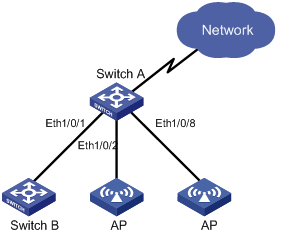
Networking and Configuration Requirements
l Switch A is an S3600 Ethernet switch supporting PoE and Switch B can be PoE powered.
l The Ethernet 1/0/1 and Ethernet 1/0/2 ports of Switch A are connected to Switch B and an Access Point (AP) respectively; the Ethernet 1/0/8 port is intended to be connected with an important AP.
l The PSE processing software of Switch A is first upgraded online. The remotely accessed PDs are powered by Switch A.
l The power consumption of the accessed AP is 2,500 milliwatts, and the maximum power consumption of Switch B is 12,000 milliwatts.
Applicable Product Matrix
|
Product series |
Software version |
Hardware version |
|
S5600 series |
Release 1510, Release1602 |
S5600 series PoE switches |
|
S5100-EI series |
Release 2200, Release2201 |
S5100-EI series PoE switches |
|
S3600-SI/EI series |
Release 1510, Release1602 |
S3600-SI/EI series PoE switches |
|
S3100-EI series |
Release 2104, Release 2107 |
S3100-EI series PoE switches |
Configuration Procedure
# Upgrade the power processing software.
<SwitchA> system-view
[SwitchA] poe update refresh 0290_021.s19
Update PoE board successfully
# Enable the PoE feature on ports Ethernet 1/0/1, Ethernet 1/0/2 and Ethernet 1/0/8.
[SwitchA] interface Ethernet 1/0/1
[SwitchA-Ethernet1/0/1] poe enable
[SwitchA-Ethernet1/0/1] quit
[SwitchA]interface Ethernet 1/0/2
[SwitchA-Ethernet1/0/2] poe enable
[SwitchA-Ethernet1/0/2] quit
[SwitchA] interface Ethernet 1/0/8
[SwitchA-Ethernet1/0/8] poe enable
[SwitchA-Ethernet1/0/8] quit
# Set the maximum power that Ethernet 1/0/1 and Ethernet 1/0/2 can provide for all PDs to 12000 and 2500 milliwatts respectively.
[SwitchA] interface Ethernet 1/0/1
[SwitchA-Ethernet1/0/1] poe max-power 12000
[SwitchA-Ethernet1/0/1] quit
[SwitchA] interface Ethernet 1/0/2
[SwitchA-Ethernet1/0/2] poe max-power 2500
[SwitchA-Ethernet1/0/2] quit
# Set the PoE priority of Ethernet 1/0/8 to critical to guarantee power supply to the device connected to Ethernet 1/0/8.
[SwitchA] interface Ethernet 1/0/8
[SwitchA-Ethernet1/0/8] poe priority critical
[SwitchA-Ethernet1/0/8] quit
# Set the power supply management mode of the switch to auto (The default power supply management mode is auto, and this step can be omitted.).
[SwitchA] poe power-management auto
# Enable the PD compatibility detection function to allow the switch to supply power to the PDs not compliant with the 802.3af standard.
[SwitchA] poe legacy enable
# View the power supply status of all the ports on the switch after the configuration.
[SwitchA] display poe interface
PORT INDEX POWER ENABLE MODE PRIORITY STATUS
Ethernet1/0/1 on enable signal low Standard PD was detected
Ethernet1/0/2 on enable signal low Standard PD was detected
Ethernet1/0/3 off enable signal low detection is in process
Ethernet1/0/4 off enable signal low detection is in process
Ethernet1/0/5 off enable signal low detection is in process
Ethernet1/0/6 off enable signal low detection is in process
Ethernet1/0/7 off enable signal low detection is in process
Ethernet1/0/8 on enable signal critical Standard PD was detected
……
# View the PoE power information of all the ports on the switch.
<SwitchA> display poe interface power
PORT INDEX POWER (mW) PORT INDEX POWER (mW)
Ethernet1/0/1 11500 Ethernet1/0/2 2300
Ethernet1/0/3 0 Ethernet1/0/4 0
Ethernet1/0/5 0 Ethernet1/0/6 0
Ethernet1/0/7 0 Ethernet1/0/8 2400
Complete Configuration
#
poe legacy enable
#
interface Ethernet1/0/1
poe enable
poe max-power 12000
#
interface Ethernet1/0/2
poe enable
poe max-power 2500
#
interface Ethernet1/0/8
poe enable
poe priority critical
Precautions
PoE Profile Configuration
A PoE profile is a set of PoE configurations, including multiple PoE features.
Features of PoE profile:
l When users connect a PD to a PoE-profile-enabled port, the PoE configurations in the PoE profile will be enabled on the port.
Network Diagram
Figure 1-2 Network diagram for PoE profile configuration
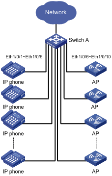
Networking and Configuration Requirements
Switch A is an S3600 Ethernet switch supporting PoE. Ethernet 1/0/1 through Ethernet 1/0/10 of Switch A are used by users of group A, whom have the following requirements:
l The PoE function can be enabled on all ports in use.
l Signal mode is used to supply power.
l The PoE priority for Ethernet 1/0/1 through Ethernet 1/0/5 is critical, whereas the PoE priority for Ethernet 1/0/6 through Ethernet 1/0/10 is high.
l The maximum power for Ethernet 1/0/1 through Ethernet 1/0/5 is 3000 milliwatts, whereas the maximum power for Ethernet 1/0/6 through Ethernet 1/0/10 is 15400 milliwatts.
Based on the above requirements, two PoE profiles are made for users of group A.
l Apply PoE profile 1 for Ethernet 1/0/1 through Ethernet 1/0/5;
l Apply PoE profile 2 for Ethernet 1/0/6 through Ethernet 1/0/10.
Applicable Product Matrix
|
Product series |
Software version |
Hardware version |
|
S5600 series |
Release 1510, Release1602 |
S5600 series PoE switches |
|
S5100-EI series |
Release 2200, Release2201 |
S5100-EI series PoE switches |
|
S3600-SI/EI series |
Release 1510, Release1602 |
S3600-SI/EI series PoE switches |
|
S3100-EI series |
Release 2104, Release 2107 |
S3100-EI series PoE switches |
Configuration Procedure
# Create Profile1 and enter PoE profile view.
<SwitchA> system-view
[SwitchA] poe-profile Profile1
# In Profile1, add the PoE policy configuration applicable to Ethernet 1/0/1 through Ethernet 1/0/5 for users of group A.
[SwitchA-poe-profile-Profile1] poe enable
[SwitchA-poe-profile-Profile1] poe mode signal
[SwitchA-poe-profile-Profile1] poe priority critical
[SwitchA-poe-profile-Profile1] poe max-power 3000
[SwitchA-poe-profile-Profile1] quit
# Create Profile2 and enter PoE profile view.
[SwitchA] poe-profile Profile2
# In Profile2, add the PoE policy configuration applicable to Ethernet 1/0/6 through Ethernet 1/0/10 for users of group A.
[SwitchA-poe-profile-Profile2] poe enable
[SwitchA-poe-profile-Profile2] poe mode signal
[SwitchA-poe-profile-Profile2] poe priority high
[SwitchA-poe-profile-Profile2] poe max-power 15400
[SwitchA-poe-profile-Profile2] quit
# Apply the configured Profile1 to Ethernet 1/0/1 through Ethernet 1/0/5.
[SwitchA] apply poe-profile Profile1 interface Ethernet1/0/1 to Ethernet1/0/5
# Apply the configured Profile2 to Ethernet 1/0/6 through Ethernet 1/0/10.
[SwitchA] apply poe-profile Profile2 interface Ethernet1/0/6 to Ethernet1/0/10
Complete Configuration
#
poe-profile Profile1
poe enable
poe max-power 3000
poe priority critical
poe-profile Profile2
poe enable
poe priority high
#
interface Ethernet1/0/1
apply poe-profile Profile1
#
interface Ethernet1/0/2
apply poe-profile Profile1
#
interface Ethernet1/0/3
apply poe-profile Profile1
#
interface Ethernet1/0/4
apply poe-profile Profile1
#
interface Ethernet1/0/5
apply poe-profile Profile1
#
interface Ethernet1/0/6
apply poe-profile Profile2
#
interface Ethernet1/0/7
apply poe-profile Profile2
#
interface Ethernet1/0/8
apply poe-profile Profile2
#
interface Ethernet1/0/9
apply poe-profile Profile2
#
interface Ethernet1/0/10
apply poe-profile Profile2
Precautions
1) When the apply poe-profile command is used to apply a PoE profile to a port, some PoE features can be applied successfully while some cannot. PoE profiles are applied to H3C low-end PoE switches according to the following rules:
l When the apply poe-profile command is used to apply a PoE profile to a port, the PoE profile is applied successfully as long as one PoE feature in the PoE profile is applied properly. When the display current-configuration command is used for query, it is displayed that the PoE profile is applied properly to the port.
l If one or more features in the PoE profile are not applied properly on a port, the switch will prompt explicitly which PoE features in the PoE profile are not applied properly on which ports.
2) If you cannot apply a PoE profile to a PoE port, it may be due to the following reasons:
l Some of the PoE features in the PoE profile have been configured through other modes;
l Some of the PoE features in the PoE profile are not compliant with the configuration requirements for PoE ports;
l Another PoE profile has been applied to this PoE port.
You can solve the problem in the following ways:
l In the first case, you can solve the problem by removing the original configurations.
l In the second case, you need to modify some configurations in the PoE profile.
In the third case, you need to remove the application of the undesired PoE profile from the PoE port.