- Table of Contents
-
- H3C Low-End Ethernet Switches Configuration Guide(V1.01)
- 01-Login Configuration Guide
- 02-VLAN Configuration Guide
- 03-IP Address Configuration Guide
- 04-Voice VLAN Configuration Guide
- 05-GVRP Configuration Guide
- 06-Ethernet Interface Basic Configuration Guide
- 07-Link Aggregation Configuration Guide
- 08-Port Isolation Configuration Guide
- 09-Port Security Configuration Guide
- 10-Port Binding Configuration Guide
- 11-MAC Address Table Management Configuration Guide
- 12-DLDP Configuration Guide
- 13-Auto Detect Configuration Guide
- 14-MSTP Configuration Guide
- 15-Routing Configuration Guide
- 16-Multicast Configuration Guide
- 17-802.1x Configuration Guide
- 18-AAA Configuration Guide
- 19-MAC Authentication Configuration Guide
- 20-VRRP Configuration Guide
- 21-ARP Configuration Guide
- 22-DHCP Configuration Guide
- 23-ACL Configuration Guide
- 24-QoS-QoS Profile Configuration Guide
- 25-Web Cache Redirection Configuration Guide
- 26-Mirroring Configuration Guide
- 27-IRF Configuration Guide
- 28-Cluster Configuration Guide
- 29-PoE-PoE Profile Configuration Guide
- 30-UDP Helper Configuration Guide
- 31-SNMP-RMON Configuration Guide
- 32-NTP Configuration Guide
- 33-SSH Configuration Guide
- 34-FTP and TFTP Configuration Guide
- 35-Information Center Configuration Guide
- 36-VLAN-VPN Configuration Guide
- 37-HWPing Configuration Guide
- 38-DNS Configuration Guide
- 39-Access Management Configuration Guide
- 40-Web Authentication Configuration Guide
- 41-IPv6 Management Configuration Guide
- 42-Smart link - Monitor Link Configuration Guide
- 43-VLAN Mapping Configuration Guide
- Related Documents
-
| Title | Size | Download |
|---|---|---|
| 28-Cluster Configuration Guide | 123.07 KB |
1 Cluster Configuration Guide·
Networking and Configuration Requirements
Network Management Interface Configuration
Networking and Configuration Requirements
Cluster Configuration in Real Networking
Networking and Configuration Requirements
Cluster Configuration
Network Diagram
Figure 1-1 Network diagram for cluster
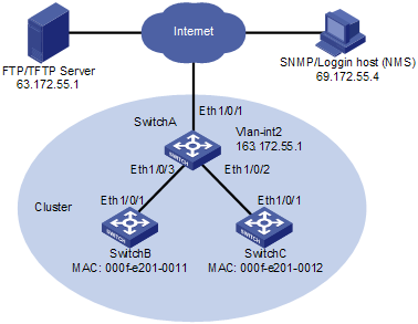
Networking and Configuration Requirements
Three switches form a cluster, where:
l Switch A serves as the management device.
l The other two switches are member devices.
Serving as the management device, Switch A manages the two member devices. The configurations for the cluster are as follows:
l The two member devices are connected to Ethernet 1/0/2 and Ethernet 1/0/3 of the management device.
l The management device connects to the Internet through Ethernet 1/0/1.
l Ethernet 1/0/1 belongs to VLAN 2, whose interface IP address is 163.172.55.1.
l All the devices in the cluster share the same FTP/TFTP server.
l The FTP/TFTP server uses IP address 63.172.55.1.
l The NMS/logging host uses IP address 69.172.55.4.
Applicable Product Matrix
|
Product series |
Software version |
Hardware version |
|
S5600 series |
Release 1510, Release1602 |
All versions |
|
S5100-SI/EI series |
Release 2200, Release2201 |
All versions |
|
S3600-SI/EI series |
Release 1510, Release1602 |
All versions |
|
S3100-EI series |
Release 2104, Release 2107 |
All versions |
|
S3100-C-SI series S3100-T-SI series |
Release 0011, Release 2102, Release 2107 |
All versions |
|
S3100-52P |
Release 1500, Release 1602 |
S3100-52P |
Configuration Procedure
1) Configure the member devices (taking one member as an example, and the configuration on the other member is the same as that in the example)
# Enable NDP globally and on Ethernet 1/0/1.
<SwitchB> system-view
[SwitchB] ndp enable
[SwitchB] interface Ethernet 1/0/1
[SwitchB-Ethernet1/0/1] ndp enable
[SwitchB-Ethernet1/0/1] quit
# Enable NTDP globally and on Ethernet 1/0/1.
[SwitchB] ntdp enable
[SwitchB] interface Ethernet 1/0/1
[SwitchB-Ethernet1/0/1] ntdp enable
[SwitchB-Ethernet1/0/1] quit
# Enable the cluster function.
[SwitchA] cluster enable
2) Configure the management device
# Create VLAN 2 and add port Ethernet 1/0/1 to VLAN 2.
<SwitchA> system-view
[SwitchA] vlan 2
[SwitchA-vlan2] port Ethernet 1/0/1
[SwitchA-vlan2] quit
# Configure the IP address for VLAN-interface 2 as 163.172.55.1.
[SwitchA] interface Vlan-interface 2
[SwitchA-Vlan-interface2] ip address 163.172.55.1 255.255.255.0
[SwitchA-Vlan-interface2] quit
# Disable NDP on Ethernet 1/0/1 of the management device.
[SwitchA] ndp enable
[SwitchA] undo ndp enable intferface Ethernet 1/0/1
[SwitchA] interface Ethernet 1/0/1
[SwitchA-Ethernet1/0/1] undo ntdp enable
[SwitchA-Ethernet1/0/1] quit
# Enable NDP on Ethernet 1/0/2 and Ethernet 1/0/3.
[SwitchA] interface Ethernet 1/0/2
[SwitchA-Ethernet1/0/2] ndp enable
[SwitchA-Ethernet1/0/2] quit
[SwitchA] interface Ethernet 1/0/3
[SwitchA-Ethernet1/0/3] ndp enable
[SwitchA-Ethernet1/0/3] quit
# Set the holdtime of NDP information to 200 seconds.
[SwitchA] ndp timer aging 200
# Set the interval between sending NDP packets to 70 seconds.
[SwitchA] ndp timer hello 70
# Enable NTDP globally and on Ethernet 1/0/2 and Ethernet 1/0/3.
[SwitchA] ntdp enable
[SwitchA] interface Ethernet 1/0/2
[SwitchA-Ethernet1/0/2] ntdp enable
[SwitchA-Ethernet1/0/2] quit
[SwitchA] interface Ethernet 1/0/3
[SwitchA-Ethernet1/0/3] ntdp enable
[SwitchA-Ethernet1/0/3] quit
# Set the topology collection range to two hops.
[SwitchA] ntdp hop 2
# Set the delay for a member device to forward topology collection request to 150 ms.
[SwitchA] ntdp timer hop-delay 150
# Set the delay for a port of a member device to forward topology collection request to 15 ms.
[SwitchA] ntdp timer port-delay 15
# Set the topology collection interval to three minutes.
[SwitchA] ntdp timer 3
# Enable the cluster function.
[SwitchA] cluster enable
# Enter cluster view.
[SwitchA] cluster
[SwitchA-cluster]
# Configure a private IP address pool for a cluster. The IP address pool contains six IP addresses, starting from 172.16.0.1.
[SwitchA-cluster] ip-pool 172.16.0.1 255.255.255.248
# Name and build a cluster.
[SwitchA-cluster] build aaa
[aaa_0.SwitchA-cluster]
# Add the two switches attached to the management device to the cluster.
[aaa_0.SwitchA-cluster] add-member 1 mac-address 00e0-fc01-0011
[aaa_0.SwitchA-cluster] add-member 17 mac-address 00e0-fc01-0012
# Set the holdtime of member device information to 100 seconds.
[aaa_0.SwitchA-cluster] holdtime 100
# Set the interval between sending handshake packets to 10 seconds.
[aaa_0.SwitchA-cluster] timer 10
# Configure VLAN-interface 2 as the network management interface.
[aaa_0. SwitchA-cluster] nm-interface Vlan-interface 2
# Configure the shared FTP server, TFTP server, logging host and SNMP host for the cluster.
[aaa_0.SwitchA-cluster] ftp-server 63.172.55.1
[aaa_0.SwitchA-cluster] tftp-server 63.172.55.1
[aaa_0.SwitchA-cluster] logging-host 69.172.55.4
[aaa_0.SwitchA-cluster] snmp-host 69.172.55.4
3) Perform the following operations on the member devices (taking Switch B as an example)
After the devices attached to the management device are added to the cluster, perform the following operations on the member devices.
# Connect the member device to the remote FTP server shared by the cluster.
<aaa_1.SwitchB> ftp cluster
# Download file aaa.txt from the shared TFTP server to the member device.
<aaa_1.SwitchB> tftp cluster get aaa.txt
# Upload file bbb.txt from the member device to the shared TFTP server.
<aaa_1.SwitchB> tftp cluster put bbb.txt
Complete Configuration
1) Configurations on the management device
#
interface Vlan-interface2
ip address 163.172.55.1 255.255.255.0
#
ntdp hop 2
ntdp timer port-delay 15
ntdp timer hop-delay 150
ntdp timer 3
#
ndp timer hello 70
ndp timer aging 200
#
cluster
ip-pool 172.16.0.1 255.255.255.248
build aaa
holdtime 100
nm-interface Vlan-interface2
ftp-server 63.172.55.1
tftp-server 63.172.55.1
logging-host 69.172.55.4
snmp-host 69.172.55.4
#
2) Configurations on the member devices
Functions configured on the member devices are enabled by default and thus are not in the configuration file.
Precautions
l After the above configuration, you can execute the cluster switch-to { member-number | mac-address H-H-H } command on the management device to switch to the view of a member device to maintain and manage the member device, and then use the cluster switch-to administrator command to return to the view of the management device.
l On the management device, you can use the reboot member command to reboot a member device.
l After the above configuration, you can receive logs and SNMP trap messages of all the cluster members on the NMS.
l The switches cannot be used as TFTP servers.
l It is recommended not to transmit data packets in the management VLAN.
Network Management Interface Configuration
Network Diagram
Figure 1-2 Network diagram for network management interface configuration
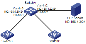
Networking and Configuration Requirements
l Configure VLAN-interface 2 as the network management interface.
l Configure VLAN 3 as the management VLAN.
l The IP address of the FTP server is 192.168.4.3.
l Switch A is the management switch.
l Switches B and C are the member switches.
Table 1-1 Connection information of the management switch
|
VLAN |
IP address |
Connection port |
|
VLAN 3, connecting Switch B or Switch C) |
192.168.5.30/24 |
Ethernet 1/0/1 |
|
VLAN 2, connecting the FTP Sever) |
192.168.4.22/24 |
Ethernet 1/0/2 |
Applicable Product Matrix
|
Product series |
Software version |
Hardware version |
|
S5600 series |
Release 1510, Release 1602 |
All versions |
|
S3600-SI/EI series |
Release 1510, Release 1602 |
All versions |
Configuration Procedure
Perform the following configurations on Switch A.
# Enter system view, create VLAN 3 and add Ethernet 1/0/1 to VLAN 3.
<SwitchA> system-view
[SwitchA] vlan 3
[SwitchA-vlan3] port Ethernet 1/0/1
[SwitchA-vlan3] quit
# Configure VLAN 3 as the management VLAN.
[SwitchA] management-vlan 3
# Configure the IP address of VLAN-interface 3 as 192.168.5.30.
[SwitchA] interface Vlan-interface 3
[SwitchA-Vlan-interface3] ip address 192.168.5.30 255.255.255.0
[SwitchA-Vlan-interface3] quit
# Add Ethernet 1/0/2 to VLAN 2.
[SwitchA] vlan 2
[SwitchA-vlan2] port Ethernet 1/0/2
[SwitchA-vlan2] quit
# Configure the IP address of VLAN-interface 2 as 192.168.4.22.
[SwitchA] interface Vlan-interface 2
[SwitchA-Vlan-interface2] ip address 192.168.4.22 255.255.255.0
[SwitchA-Vlan-interface2] quit
# Enable the cluster function.
[SwitchA] cluster enable
# Enter cluster view.
[SwitchA] cluster
[SwitchA -cluster]
# Configure a private IP address pool for a cluster. The IP address pool contains 30 IP addresses, starting from 192.168.5.1.
[SwitchA-cluster] ip-pool 192.168.5.1 255.255.255.224
# Name and build a cluster.
[SwitchA-cluster] build aaa
[aaa_0.SwitchA-cluster]
# Configure VLAN-interface 2 as the network management interface.
[aaa_0.SwitchA] cluster
[aaa_0.SwitchA-cluster] nm-interface Vlan-interface 2
Complete Configuration
#
vlan 2
#
vlan 3
#
interface Vlan-interface2
ip address 192.168.4.22 255.255.255.0
#
interface Vlan-interface3
ip address 192.168.5.30 255.255.255.0
#
management-vlan 3
#
interface Ethernet1/0/1
port access vlan 3
#
interface Ethernet1/0/2
port access vlan 2
#
cluster
ip-pool 192.168.5.1 255.255.255.224
build aaa
nm-interface Vlan-interface2
#
Precautions
l The default network management interface is the management VLAN interface.
l There can be only one network management interface. A new configuration will overwrite the previous one.
l The network management interface can be configured on the management switch only.
Cluster Configuration in Real Networking
In a complicated network, you can manage switches remotely in a bulk through HGMP, reducing the workload of the network configuration.
Network Diagram
Figure 1-3 Network diagram for HGMP cluster
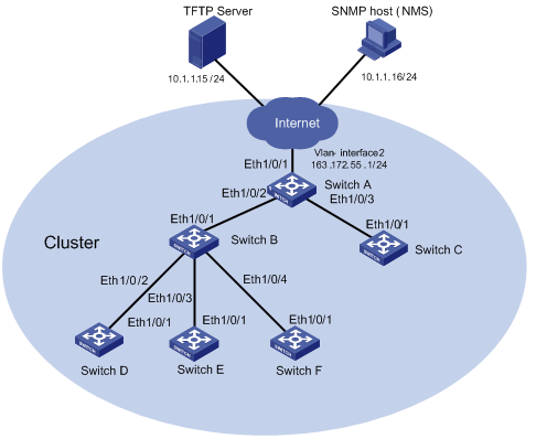
Networking and Configuration Requirements
l The IP address of the management switch (Switch A) is 10.1.1.17.
l Configure the IP address of the TFTP server as 10.1.1.15.
l Configure the IP address of the SNMP NMS as 10.1.1.16.
l The whole cluster shares the same TFTP server and SNMP NMS.
Management switch Switch A:
l Ethernet 1/0/1 belongs to VLAN 2, whose interface IP address is 163.172.55.1.
l Two member switches are connected to Ethernet 1/0/1 and Ethernet 1/0/2 of the management switch.
The member switches:
l Member switch Switch B is connected to Switch D through Ethernet 1/0/2.
l Switch B is connected to Switch E through Ethernet 1/0/3.
l Switch B is connected to Switch F through Ethernet 1/0/4.
Applicable Product Matrix
|
Product series |
Software version |
Hardware version |
|
S5600 series |
Release 1510, Release1602 |
All versions |
|
S5100-SI/EI series |
Release 2200, Release2201 |
All versions |
|
S3600-SI/EI series |
Release 1510, Release1602 |
All versions |
|
S3100-EI series |
Release 2104, Release 2107 |
All versions |
|
S3100-C-SI series S3100-T-SI series |
Release 0011, Release 2102, Release 2107 |
All versions |
|
S3100-52P |
Release 1500, Release 1602 |
S3100-52P |
Configuration Procedure
1) Configure the member devices (taking Switch B as an example)
# Enable NDP globally.
<SwitchA> system-view
[SwitchA] ndp enable
# Enable NDP on Ethernet 1/0/1, Ethernet 1/0/2, Ethernet1/0/3, and Ethernet1/0/4.
[SwitchA] interface Ethernet 1/0/1
[SwitchA-Ethernet1/0/1] ndp enable
[SwitchA-Ethernet1/0/1] quit
[SwitchA] interface Ethernet 1/0/2
[SwitchA-Ethernet1/0/2] ndp enable
[SwitchA-Ethernet1/0/2] quit
[SwitchA] interface Ethernet 1/0/3
[SwitchA-Ethernet1/0/3] ndp enable
[SwitchA-Ethernet1/0/3] quit
[SwitchA] interface Ethernet 1/0/4
[SwitchA-Ethernet1/0/4] ndp enable
[SwitchA-Ethernet1/0/4] quit
# Enable NTDP globally.
[SwitchA] ntdp enable
# Enable NTDP on Ethernet 1/0/1, Ethernet 1/0/2, Ethernet1/0/3, and Ethernet1/0/4.
[SwitchA] interface Ethernet 1/0/1
[SwitchA-Ethernet1/0/1] ntdp enable
[SwitchA-Ethernet1/0/1] quit
[SwitchA] interface Ethernet 1/0/2
[SwitchA-Ethernet1/0/2] ntdp enable
[SwitchA-Ethernet1/0/2] quit
[SwitchA] interface Ethernet 1/0/3
[SwitchA-Ethernet1/0/3] ntdp enable
[SwitchA-Ethernet1/0/3] quit
[SwitchA] interface Ethernet 1/0/4
[SwitchA-Ethernet1/0/4] ntdp enable
[SwitchA-Ethernet1/0/4] quit
# Enable the cluster function.
[SwitchA] cluster enable
![]()
On the member switches, ports that connect to other switches all need to be enabled with NDP and NTDP.
2) Configure the management device (Switch A)
# Disable NDP on Ethernet 1/0/1 of the management device.
<SwitchA> system-view
[SwitchA] ndp enable
[SwitchA] undo ndp enable interface Ethernet 1/0/1
# Enable NDP on Ethernet 1/0/2 and Ethernet 1/0/3.
[SwitchA] interface Ethernet 1/0/2
[SwitchA-Ethernet1/0/2] ndp enable
[SwitchA-Ethernet1/0/2] quit
[SwitchA] interface Ethernet 1/0/3
[SwitchA-Ethernet1/0/3] ndp enable
[SwitchA-Ethernet1/0/3] quit
# Set the holdtime of NDP information to 300 seconds.
[SwitchA] ndp timer aging 300
# Set the interval between sending NDP packets to 100 seconds.
[SwitchA] ndp timer hello 100
# Enable NTDP globally and on Ethernet 1/0/2 and Ethernet 1/0/3.
[SwitchA] ntdp enable
[SwitchA] interface Ethernet 1/0/2
[SwitchA-Ethernet1/0/2] ntdp enable
[SwitchA-Ethernet1/0/2] quit
[SwitchA] interface Ethernet 1/0/3
[SwitchA-Ethernet1/0/3] ntdp enable
[SwitchA-Ethernet1/0/3] quit
# Set the topology collection range to two hops.
[SwitchA] ntdp hop 2
# Set the delay for a member device to forward topology collection request to 180 ms.
[SwitchA] ntdp timer hop-delay 180
# Set the delay for a port of a member device to forward topology collection request to 20 ms.
[SwitchA] ntdp timer port-delay 20
# Set the topology collection interval to three minutes.
[SwitchA] ntdp timer 3
# Enable the cluster function.
[SwitchA] cluster enable
# Enter cluster view.
[SwitchA] cluster
[SwitchA-cluster]
# Configure a private IP address pool for a cluster. The IP address pool contains six IP addresses, starting from 172.16.0.1.
[SwitchA-cluster] ip-pool 172.16.0.1 255.255.255.248
# Name and build a cluster.
[SwitchA-cluster] build aaa
[aaa_0.SwitchA-cluster]
# Set the holdtime of member device information to 100 seconds.
[aaa_0.SwitchA-cluster] holdtime 100
# Set the interval between sending handshake packets to 10 seconds.
[aaa_0.SwitchA-cluster] timer 10
# Configure the TFTP server and SNMP NMS shared by the cluster.
[aaa_0.SwitchA-cluster] tftp-server 10.1.1.15
[aaa_0.SwitchA-cluster] snmp-host 10.1.1.16
3) Perform the following operations on the member devices (taking Switch B as an example):
After the devices attached to the management device are added to the cluster, perform the following operations on the member devices.
# Download file aaa.txt from the shared TFTP server to the member device.
<aaa_1.SwitchB> tftp cluster get aaa.txt
# Upload file bbb.txt from the member device to the shared TFTP server.
<aaa_1.SwitchB> tftp cluster put bbb.txt
Complete Configuration
1) Configuration on Switch A
#
ntdp hop 2
ntdp timer port-delay 20
ntdp timer hop-delay 180
ntdp timer 3
#
ndp timer hello 100
ndp timer aging 300
#
cluster
ip-pool 172.16.0.1 255.255.255.248
build aaa
holdtime 100
tftp-server 10.1.1.15
snmp-host 10.1.1.16
2) Configurations on the member devices
Functions configured on the member devices are enabled by default and thus are not in the configuration file.
Precautions
None