- Table of Contents
-
- H3C Low-End Ethernet Switches Configuration Guide(V1.01)
- 01-Login Configuration Guide
- 02-VLAN Configuration Guide
- 03-IP Address Configuration Guide
- 04-Voice VLAN Configuration Guide
- 05-GVRP Configuration Guide
- 06-Ethernet Interface Basic Configuration Guide
- 07-Link Aggregation Configuration Guide
- 08-Port Isolation Configuration Guide
- 09-Port Security Configuration Guide
- 10-Port Binding Configuration Guide
- 11-MAC Address Table Management Configuration Guide
- 12-DLDP Configuration Guide
- 13-Auto Detect Configuration Guide
- 14-MSTP Configuration Guide
- 15-Routing Configuration Guide
- 16-Multicast Configuration Guide
- 17-802.1x Configuration Guide
- 18-AAA Configuration Guide
- 19-MAC Authentication Configuration Guide
- 20-VRRP Configuration Guide
- 21-ARP Configuration Guide
- 22-DHCP Configuration Guide
- 23-ACL Configuration Guide
- 24-QoS-QoS Profile Configuration Guide
- 25-Web Cache Redirection Configuration Guide
- 26-Mirroring Configuration Guide
- 27-IRF Configuration Guide
- 28-Cluster Configuration Guide
- 29-PoE-PoE Profile Configuration Guide
- 30-UDP Helper Configuration Guide
- 31-SNMP-RMON Configuration Guide
- 32-NTP Configuration Guide
- 33-SSH Configuration Guide
- 34-FTP and TFTP Configuration Guide
- 35-Information Center Configuration Guide
- 36-VLAN-VPN Configuration Guide
- 37-HWPing Configuration Guide
- 38-DNS Configuration Guide
- 39-Access Management Configuration Guide
- 40-Web Authentication Configuration Guide
- 41-IPv6 Management Configuration Guide
- 42-Smart link - Monitor Link Configuration Guide
- 43-VLAN Mapping Configuration Guide
- Related Documents
-
| Title | Size | Download |
|---|---|---|
| 13-Auto Detect Configuration Guide | 155.95 KB |
1 Auto Detect Configuration Guide·
Auto Detect Implementation in Static Routing
Networking and Configuration Requirements
Auto Detect Implementation in VRRP
Networking and Configuration Requirements
Auto Detect Implementation in VLAN Interface Backup
Networking and Configuration Requirements
Auto Detect Implementation in Static Routing
You can bind a static route with a detected group, and then the auto detect function detects the reachability of the static route through the path specified in the detected group.
l The static route is valid if the detected group is reachable.
l The static route is invalid if the detected group is unreachable.
Network Diagram
Figure 1-1 Network diagram of applying auto detect to static routing
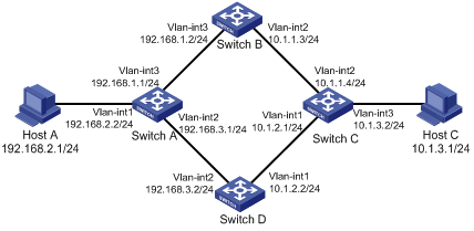
Networking and Configuration Requirements
l Make sure there is a route between Switch A and Switch B, Switch B and Switch C, Switch A and Switch D, and Switch D and Switch C.
l On Switch A, configure two static routes to Host C with different preferences. The one with higher preference (smaller value) is used as the master route, and the other as the backup route.
l Normally, Switch A adopts the master route to send data to Host C through Switch B.
l Create detected group 8 on Switch A; detect the reachability of IP address 10.1.1.4/24, with the next hop being 192.168.1.2, and the detecting number being 1.
l If the detected group 8 is reachable, the master route is valid, and Switch A adopts the master route to send data to Host C through Switch B.
l If the detected group is unreachable, the master route becomes invalid and the backup route becomes valid. Switch A adopts the backup route to send data to Host C through Switch D. When the detected group is reachable again, the master route becomes valid and the backup route becomes invalid.
l Similarly, configure two static routes to Host A on Switch C. Normally, Switch C sends data to Host A through Switch B.
Applicable Product Matrix
|
Product series |
Software version |
Hardware version |
|
S3600-SI/EI series Ethernet switches |
Release 1510,Release 1602 |
All versions |
|
S5600 series Ethernet switches |
Release 1510,Release 1602 |
All versions |
Configuration Procedure
Configure IP addresses for the interfaces according to Figure 1-1. The configuration procedure is omitted here.
l Configure Switch A
# Enter system view.
<SwitchA> system-view
# Create detected group 8.
[SwitchA] detect-group 8
# Detect the reachability of 10.1.1.4, with the next hop being 192.168.1.2, and the detecting number being 1.
[SwitchA-detect-group-8] detect-list 1 ip address 10.1.1.4 nexthop 192.168.1.2
[SwitchA-detect-group-8] quit
# Configure a static route to Switch C, and set its preference to 60.
[SwitchA] ip route-static 10.1.1.4 24 192.168.1.2 preference 60
# Configure the master static route, which is valid when the detected group is reachable.
[SwitchA] ip route-static 10.1.3.1 24 192.168.1.2 detect-group 8
# Configure the backup static route, and set its preference to 80. The backup route is valid when the detected group is unreachable.
[SwitchA] ip route-static 10.1.3.1 24 192.168.3.2 preference 80
l Configure Switch C
# Enter system view.
<SwitchC> system-view
# Create detected group 9.
[SwitchC] detect-group 9
# Detect the reachability of 10.1.1.3, with the next hop being 192.168.1.1/24, and the detecting number being 1.
[SwitchC-detect-group-9] detect-list 1 ip address 192.168.1.1 nexthop 10.1.1.3
[SwitchC-detect-group-9] quit
# Configure a static route to Switch A, and set its preference to 60.
[SwitchC] ip route-static 192.168.1.1 24 10.1.1.3 preference 60
# Configure the master route, which is valid when the detected group is reachable.
[SwitchC] ip route-static 192.168.2.1 24 10.1.1.3 detect-group 9
# Configure the backup static route, and set its preference to 80. The backup route is valid when the detected group is unreachable.
[SwitchC] ip route-static 192.168.2.1 24 10.1.2.2 preference 80
![]()
This configuration procedure only provides the auto-detect related configuration. To ensure the normal communication between Host A and Host C, corresponding static routes must already exist on Switch B and Switch D.
Complete Configuration
l Configure Switch A
#
detect-group 8
detect-list 1 ip address 10.1.1.4 nexthop 192.168.1.2
#
ip route-static 10.1.1.0 255.255.255.0 192.168.1.2 preference 60
ip route-static 10.1.3.0 255.255.255.0 192.168.1.2 preference 60 detect-group 8
ip route-static 10.1.3.0 255.255.255.0 192.168.3.2 preference 80
#
l Configure Switch C
#
detect-group 9
detect-list 1 ip address 192.168.1.1 nexthop 10.1.1.3
#
ip route-static 192.168.1.0 255.255.255.0 10.1.1.3 preference 60
ip route-static 192.168.2.0 255.255.255.0 10.1.1.3 preference 60 detect-group 9
ip route-static 192.168.2.0 255.255.255.0 10.1.2.2 preference 80
#
Precautions
In a network environment where the round trip delay of ICMP messages is longer than usual, you need to extend the timeout waiting for a reply for the group to ensure that your switch can correctly decide whether the group is reachable.
Auto Detect Implementation in VRRP
You can use the auto detect function on the master switch of a VRRP group to detect the routes from the master switch to other networks, and use the detection results (reachable/unreachable) to control the priority of the master switch, so as to realize the automatic master-backup switchover:
l The master switch remains as master when the detected group is reachable.
Network Diagram
Figure 1-2 Network diagram of applying auto detect to VRRP
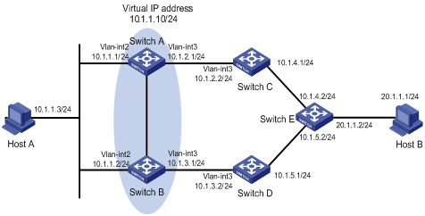
Networking and Configuration Requirements
l Make sure there is a route between Switch A and Switch C, Switch C and Switch E, Switch B and Switch D, and Switch D and Switch E.
l Create VRRP group 1 containing Switch A and Switch B, and set the virtual IP address of the group to 10.1.1.10/24.
l Normally, data of Host A is forwarded to Host B through Switch A.
Applicable Product Matrix
|
Product series |
Software version |
Hardware version |
|
S3600-EI series Ethernet switches |
Release 1510,Release 1602 |
All versions |
|
S5600 series Ethernet switches |
Release 1510,Release 1602 |
All versions |
Configuration Procedure
Configure IP addresses for the interfaces according to Figure 1-2. The configuration procedure is omitted here.
l Configure Switch A
# Create detected group 9.
<SwitchA> system-view
[SwitchA] detect-group 9
# Detect the reachability of 10.1.4.2, with the next hop being 10.1.2.2, and the detecting number being 1.
[SwitchA-detect-group-9] detect-list 1 ip address 10.1.4.2 nexthop 10.1.2.2
[SwitchA-detect-group-9] quit
# Configure an IP address for VLAN-interface 2.
[SwitchA] interface vlan-interface 2
[SwitchA-Vlan-interface2] ip address 10.1.1.1 24
# Enable VRRP on VLAN-interface 2, and set the virtual IP address of the VRRP group to 10.1.1.10.
[SwitchA-Vlan-interface2] vrrp vrid 1 virtual-ip 10.1.1.10
# Set the VRRP priority of Switch A to 110, and specify to decrease the priority by 20 when the result of detected group 9 is unreachable.
[SwitchA-Vlan-interface2] vrrp vrid 1 priority 110
[SwitchA-Vlan-interface2] vrrp vrid 1 track detect-group 9 reduced 20
l Configure Switch B
# Configure an IP address for VLAN-interface 2.
<SwitchB> system-view
[SwitchB] interface vlan-interface 2
[SwitchB-Vlan-interface2] ip address 10.1.1.2 24
# Enable VRRP on VLAN-interface 2, and set the virtual IP address of the VRRP group to 10.1.1.10.
[SwitchB-Vlan-interface2] vrrp vrid 1 virtual-ip 10.1.1.10
# Set the VRRP priority of Switch B to 100.
[SwitchB-Vlan-interface2] vrrp vrid 1 priority 100
![]()
This configuration procedure only provides the auto-detect and VRRP related configuration. To ensure the operation of auto detect, you must ensure that Switch A and Switch E have at least one reachable route to each other.
Complete Configuration
l Configure Switch A
#
detect-group 9
detect-list 1 ip address 10.1.4.2 nexthop 10.1.2.2
#
interface Vlan-interface2
ip address 10.1.1.1 255.255.255.0
vrrp vrid 1 virtual-ip 10.1.1.10
vrrp vrid 1 priority 110
vrrp vrid 1 track detect-group 9 reduced 20
l Configure Switch B
#
interface Vlan-interface2
ip address 10.1.1.2 255.255.255.0
vrrp vrid 1 virtual-ip 10.1.1.10
#
Precautions
In a network environment where the round trip delay of ICMP messages is longer than usual, you need to extend the timeout waiting for a reply for the group to ensure that your switch can correctly decide whether the group is reachable.
Auto Detect Implementation in VLAN Interface Backup
You can implement VLAN interface backup through auto detect. When data can be transmitted through two VLAN interfaces on the switch to the same destination, configure one of the VLAN interfaces as the active interface and the other as the standby interface. Through the auto detect function, the standby interface is enabled automatically when the active fails, so as to ensure the data transmission:
l In normal situations (that is, when the detected group is reachable), the standby VLAN interface is down and packets are sent to the destination through the active VLAN interface.
l When the communication between the active VLAN interface and the destination fails (that is, the detected group is unreachable), the system enables the backup VLAN interface.
Network Diagram
Figure 1-3 Network diagram of applying auto detect to VLAN interface backup
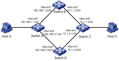
Networking and Configuration Requirements
l Make sure that there is a route between Switch A and Switch B, Switch B and Switch C, Switch A and Switch D, and Switch D and Switch C.
l Create detected group 10 on Switch A to detect the connectivity between Switch A and Switch C. Configure VLAN-interface 1 to be the active interface, which is enabled when the detected group 10 is reachable; Configure VLAN-interface 2 to be the standby interface, which is enabled when the detected group 10 is unreachable.
l Create detected group 9 on Switch C to detect the connectivity between Switch C and Switch A. Configure VLAN-interface 2 to be the active interface, which is enabled when the detected group 9 is reachable; Configure VLAN-interface 1 to be the standby interface, which is enabled when the detected group 9 is unreachable.
Applicable Product Matrix
|
Product series |
Software version |
Hardware version |
|
S3600-SI/EI series Ethernet switches |
Release 1510,Release 1602 |
All versions |
|
S5600 series Ethernet switches |
Release 1510,Release 1602 |
All versions |
Configuration Procedure
l Configure Switch A
# Enter system view.
<SwitchA> system-view
# Configure an IP address for VLAN-interface 1.
[SwitchA] interface vlan-interface 1
[SwitchA-Vlan-interface1] ip address 192.168.1.1 24
[SwitchA-Vlan-interface1] quit
# Configure an IP address for VLAN-interface 2.
[SwitchA] interface vlan-interface 2
[SwitchA-Vlan-interface2] ip address 192.168.3.1 24
[SwitchA-Vlan-interface2] quit
# Create detected group 10.
[SwitchA] detect-group 10
# Detect the reachability of 10.1.1.4, with the next hop being 192.168.1.2, and the detecting number being 1.
[SwitchA-detect-group-10] detect-list 1 ip address 10.1.1.4 nexthop 192.168.1.2
[SwitchA-detect-group-10] quit
# Configure VLAN-interface 2 as the standby interface, which is enabled when the detected group 10 is unreachable.
[SwitchA] interface vlan-interface 2
[SwitchA-Vlan-interface2] standby detect-group 10
l Configure Switch C
# Enter system view.
<SwitchC> system-view
# Configure an IP address for VLAN-interface 2.
[SwitchC] interface vlan-interface 2
[SwitchC-Vlan-interface2] ip address 10.1.1.4 24
[SwitchC-Vlan-interface2] quit
# Configure an IP address for VLAN-interface 1.
[SwitchC] interface vlan-interface 1
[SwitchC-Vlan-interface1] ip address 10.1.2.1 24
[SwitchC-Vlan-interface1] quit
# Create detected group 9.
[SwitchC] detect-group 9
# Detect the reachability of 192.168.1.1/24, with the next hop being 10.1.1.3, and the detecting number being 1.
[SwitchC-detect-group-9] detect-list 1 ip address 192.168.1.1 nexthop 10.1.1.3
[SwitchC-detect-group-9] quit
# Configure VLAN-interface 1 as the standby interface, which is enabled when the detected group 9 is unreachable.
[SwitchC] interface vlan-interface 1
[SwitchC-Vlan-interface1] standby detect-group 9
![]()
This configuration procedure only provides the auto-detect related configuration. To use auto detect function properly, a Switch A-to-Switch B-to-Switch C route must already exist on Switch A, and a Switch C-to-Switch B-to-Switch A route must already exist on Switch C.
Complete Configuration
l Configure Switch A
#
detect-group 10
detect-list 1 ip address 10.1.1.4 nexthop 192.168.1.2
#
vlan 1
#
vlan 2
#
interface Vlan-interface1
ip address 192.168.1.1 255.255.255.0
#
interface Vlan-interface2
standby detect-group 10
ip address 192.168.3.1 255.255.255.0
l Configure Switch C
#
detect-group 9
detect-list 1 ip address 192.168.1.1 nexthop 10.1.1.3
#
vlan 1
#
vlan 2
#
interface Vlan-interface1
standby detect-group 9
ip address 10.1.2.1 255.255.255.0
#
interface Vlan-interface2
ip address 10.1.1.4 255.255.255.0
#
Precautions
In a network environment where the round trip delay of ICMP messages is longer than usual, you need to extend the timeout waiting for a reply for the group to ensure that your switch can correctly decide whether the group is reachable.