- Table of Contents
-
- H3C Low-End Ethernet Switches Configuration Guide(V1.01)
- 01-Login Configuration Guide
- 02-VLAN Configuration Guide
- 03-IP Address Configuration Guide
- 04-Voice VLAN Configuration Guide
- 05-GVRP Configuration Guide
- 06-Ethernet Interface Basic Configuration Guide
- 07-Link Aggregation Configuration Guide
- 08-Port Isolation Configuration Guide
- 09-Port Security Configuration Guide
- 10-Port Binding Configuration Guide
- 11-MAC Address Table Management Configuration Guide
- 12-DLDP Configuration Guide
- 13-Auto Detect Configuration Guide
- 14-MSTP Configuration Guide
- 15-Routing Configuration Guide
- 16-Multicast Configuration Guide
- 17-802.1x Configuration Guide
- 18-AAA Configuration Guide
- 19-MAC Authentication Configuration Guide
- 20-VRRP Configuration Guide
- 21-ARP Configuration Guide
- 22-DHCP Configuration Guide
- 23-ACL Configuration Guide
- 24-QoS-QoS Profile Configuration Guide
- 25-Web Cache Redirection Configuration Guide
- 26-Mirroring Configuration Guide
- 27-IRF Configuration Guide
- 28-Cluster Configuration Guide
- 29-PoE-PoE Profile Configuration Guide
- 30-UDP Helper Configuration Guide
- 31-SNMP-RMON Configuration Guide
- 32-NTP Configuration Guide
- 33-SSH Configuration Guide
- 34-FTP and TFTP Configuration Guide
- 35-Information Center Configuration Guide
- 36-VLAN-VPN Configuration Guide
- 37-HWPing Configuration Guide
- 38-DNS Configuration Guide
- 39-Access Management Configuration Guide
- 40-Web Authentication Configuration Guide
- 41-IPv6 Management Configuration Guide
- 42-Smart link - Monitor Link Configuration Guide
- 43-VLAN Mapping Configuration Guide
- Related Documents
-
| Title | Size | Download |
|---|---|---|
| 25-Web Cache Redirection Configuration Guide | 43.84 KB |
1 Web Cache Redirection Configuration Guide
Configuring Web Cache Redirection
Networking and Configuration Requirements
1 Web Cache Redirection Configuration Guide
Configuring Web Cache Redirection
Network Diagram
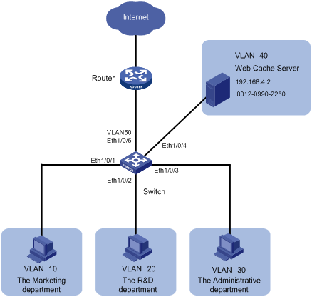
Figure 1-1 Network diagram for Web cache redirection configuration
Networking and Configuration Requirements
The network of a company is described as follows:
l The marketing department uses VLAN 10 and is connected to Ethernet 1/0/1 of the switch. The IP address of the VLAN interface for VLAN 10 is 192.168.1.1/24.
l The R&D department uses VLAN 20 and is connected to Ethernet 1/0/2 of the switch. The IP address of the VLAN interface for VLAN 20 is 192.168.2.1/24.
l The administration department uses VLAN 30 and is connected to Ethernet 1/0/3 of the switch. The IP address of the VLAN interface for VLAN 30 is 192.168.3.1/24.
l The Web cache server belongs to VLAN 40 and is connected to Ethernet 1/0/4 of the switch. The IP address of the VLAN interface for VLAN 40 is 192.168.4.1/24. The IP address and the MAC address of the Web cache server is 192.168.4.2 and 0012-0990-2250.
l The router is connected to Ethernet 1/0/5 of the switch. The switch accesses the Internet through a router. Ethernet 1/0/5 belongs to VLAN 50 whose VLAN interface is assigned IP address 192.168.5.1/24.
Applicable Product Matrix
|
Product series |
Software version |
Hardware version |
|
S3600-EI series |
Release 1510, Release 1602 |
All versions |
Configuration Procedure
# Create VLAN 10 for the marketing department and configure the IP address of VLAN-interface 10 as 192.168.1.1.
<H3C> system-view
[H3C] vlan 10
[H3C-vlan10] port Ethernet 1/0/1
[H3C-vlan10] quit
[H3C] interface Vlan-interface 10
[H3C-Vlan-interface10] ip address 192.168.1.1 24
[H3C-Vlan-interface10] quit
# Create VLAN 20 for the R&D department and configure the IP address of VLAN-interface 20 as 192.168.2.1.
[H3C] vlan 20
[H3C-vlan20] port Ethernet 1/0/2
[H3C-vlan20] quit
[H3C] interface Vlan-interface 20
[H3C-Vlan-interface20] ip address 192.168.2.1 24
[H3C-Vlan-interface20] quit
# Create VLAN 30 for the administration department and configure the IP address of VLAN-interface 30 as 192.168.3.1.
[H3C] vlan 30
[H3C-vlan30] port Ethernet 1/0/3
[H3C-vlan30] quit
[H3C] interface Vlan-interface 30
[H3C-Vlan-interface30] ip address 192.168.3.1 24
[H3C-Vlan-interface30] quit
# Create VLAN 40 for the Web cache server and configure the IP address of VLAN-interface 40 as 192.168.4.1.
[H3C] vlan 40
[H3C-vlan40] port Ethernet 1/0/4
[H3C-vlan40] quit
[H3C] interface Vlan-interface 40
[H3C-Vlan-interface40] ip address 192.168.4.1 24
[H3C-Vlan-interface40] quit
# Create VLAN 50 for the switch to connect to the router and configure the IP address of VLAN-interface 50 as 192.168.5.1.
[H3C] vlan 50
[H3C-vlan50] port Ethernet 1/0/5
[H3C-vlan50] quit
[H3C] interface Vlan-interface 50
[H3C-Vlan-interface50] ip address 192.168.5.1 24
[H3C-Vlan-interface50] quit
# Configure Ethernet 1/0/4, the port connected to the Web cache server, as a trunk port, and configure the port to permit the packets of VLAN 40 and VLAN 50 to pass through.
[H3C] interface Ethernet 1/0/4
[H3C-Ethernet1/0/4] port link-type trunk
[H3C-Ethernet1/0/4] port trunk permit vlan 40 50
[H3C-Ethernet1/0/4] quit
# Enable Web cache redirection to redirect all the HTTP packets received from VLAN 10, VLAN 20, and VLAN 30 to the Web cache server.
[H3C] webcache address 192.168.4.2 mac 0012-0990-2250 vlan 40 port Ethernet 1/0/4
[H3C] webcache redirect-vlan 10
[H3C] webcache redirect-vlan 20
[H3C] webcache redirect-vlan 30
Complete Configuration
#
vlan 10
#
vlan 20
#
vlan 30
#
vlan 40
#
vlan 50
#
interface Vlan-interface10
ip address 192.168.1.1 255.255.255.0
#
interface Vlan-interface20
ip address 192.168.2.1 255.255.255.0
#
interface Vlan-interface30
ip address 192.168.3.1 255.255.255.0
#
interface Vlan-interface40
ip address 192.168.4.1 255.255.255.0
#
interface Vlan-interface50
ip address 192.168.5.1 255.255.255.0
#
interface Ethernet1/0/1
port access vlan 10
#
interface Ethernet1/0/2
port access vlan 20
#
interface Ethernet1/0/3
port access vlan 30
#
interface Ethernet1/0/4
port link-type trunk
port trunk permit vlan 1 40 50
webcache address 192.168.4.2 mac 0012-0990-2250 vlan 40
#
interface Ethernet1/0/5
port access vlan 50
#
webcache redirect-vlan 10
webcache redirect-vlan 20
webcache redirect-vlan 30
#
Precautions
When configuring Web cache redirection, consider the following:
l To ensure the success of Web cache redirection, check that the VLAN-interfaces for all the involved VLANs (VLAN 40, VLAN 10, VLAN 20, and VLAN 30) are up.
l Do not redirect the HTTP packets destined for VLAN 40 to the Web cache server.
l Enabling STP can cause Web cache redirection failure.