- Table of Contents
-
- H3C Low-End Ethernet Switches Configuration Guide(V1.01)
- 01-Login Configuration Guide
- 02-VLAN Configuration Guide
- 03-IP Address Configuration Guide
- 04-Voice VLAN Configuration Guide
- 05-GVRP Configuration Guide
- 06-Ethernet Interface Basic Configuration Guide
- 07-Link Aggregation Configuration Guide
- 08-Port Isolation Configuration Guide
- 09-Port Security Configuration Guide
- 10-Port Binding Configuration Guide
- 11-MAC Address Table Management Configuration Guide
- 12-DLDP Configuration Guide
- 13-Auto Detect Configuration Guide
- 14-MSTP Configuration Guide
- 15-Routing Configuration Guide
- 16-Multicast Configuration Guide
- 17-802.1x Configuration Guide
- 18-AAA Configuration Guide
- 19-MAC Authentication Configuration Guide
- 20-VRRP Configuration Guide
- 21-ARP Configuration Guide
- 22-DHCP Configuration Guide
- 23-ACL Configuration Guide
- 24-QoS-QoS Profile Configuration Guide
- 25-Web Cache Redirection Configuration Guide
- 26-Mirroring Configuration Guide
- 27-IRF Configuration Guide
- 28-Cluster Configuration Guide
- 29-PoE-PoE Profile Configuration Guide
- 30-UDP Helper Configuration Guide
- 31-SNMP-RMON Configuration Guide
- 32-NTP Configuration Guide
- 33-SSH Configuration Guide
- 34-FTP and TFTP Configuration Guide
- 35-Information Center Configuration Guide
- 36-VLAN-VPN Configuration Guide
- 37-HWPing Configuration Guide
- 38-DNS Configuration Guide
- 39-Access Management Configuration Guide
- 40-Web Authentication Configuration Guide
- 41-IPv6 Management Configuration Guide
- 42-Smart link - Monitor Link Configuration Guide
- 43-VLAN Mapping Configuration Guide
- Related Documents
-
| Title | Size | Download |
|---|---|---|
| 36-VLAN-VPN Configuration Guide | 217.91 KB |
1 VLAN-VPN Configuration Guide·
Networking and Configuration Requirements
Networking and Configuration Requirements
Networking and Configuration Requirements
Configuring VLAN-VPN
With VLAN-VPN enabled, a device tags a private network packet with an outer VLAN tag, thus enabling the packet to be transmitted through the service providers’ backbone network with both inner and outer VLAN tags. After reaching the peer private network, the packet’s outer VLAN tag will be removed and the inner tag will be used for packet forwarding.
VLAN-VPN tunnels private network packets over the public backbone network in a simple way.
Network Diagram
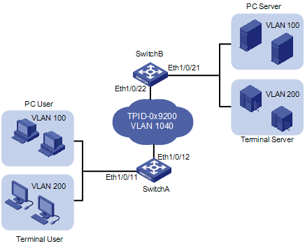
Figure 1-1 Network diagram for configuring VLAN-VPN
Networking and Configuration Requirements
As shown inFigure 1-1, Switch A and Switch B connect the users to the servers across the public network.
l The PC users and PC servers are in VLAN 100, while the terminal users and terminal servers are in VLAN 200. Both VLAN 100 and VLAN 200 are private. On the public network, there is VLAN 1040.
l Switches of other vendors are used on the public network. They use the TPID value 0x9200. This configuration is applicable only to the devices supporting TPID configuration.
l Configure VLAN-VPN on Switch A and Switch B to enable the PC users and the terminal users to communicate with their respective servers.
Applicable Product Matrix
|
Product series |
Software version |
Hardware version |
|
S5600 series |
Release 1510, Release1602 |
All versions |
|
S5100-SI/EI series |
Release 2200, Release2201 |
All versions |
|
S3600-SI/EI series |
Release 1510, Release1602 |
All versions |
|
S3100-EI series |
Release 2104, Release 2107 |
All versions |
|
S3100-C-SI series S3100-T-SI series |
Release 0011, Release 2102, Release 2107 |
All versions |
|
S3100-52P |
Release 1500, Release 1602 |
S3100-52P |
![]()
l The S3600 series and S3100-52P series switches support port-level TPID configuration.
l The S5100-SI/EI series and S3100-EI series switches support global TPID configuration.
l The S5600 series and S3100-SI series switches do not support TPID configuration.
Configuration Procedure
![]()
VLAN-VPN is mutually exclusive with each of the following functions:
l GVRP
l NTDP
l STP
l 802.1x
l MAC authentication
l IRF Fabric
By default, NTDP and STP are enabled on a port. You need to disable the two features using the undo ntdp enable and stp disable commands before enabling VLAN-VPN on the port.
l Configure Switch A
# Enable VLAN-VPN on Ethernet 1/0/11 of Switch A, using the tag of VLAN 1040 as the outer VLAN tag for packets received on the port .
<SwitchA> system-view
[SwitchA] vlan 1040
[SwitchA-vlan1040] port Ethernet 1/0/11
[SwitchA-vlan1040] quit
[SwitchA] interface Ethernet 1/0/11
[SwitchA-Ethernet1/0/11] undo ntdp enable
[SwitchA-Ethernet1/0/11] stp disable
[SwitchA-Ethernet1/0/11] vlan-vpn enable
# Set the TPID value of Ethernet 1/0/11 to 0x9200 for intercommunication with the devices in the public network.
[SwitchA-Ethernet1/0/11] vlan-vpn tpid 9200
[SwitchA-Ethernet1/0/11] quit
# Configure Ethernet 1/0/12 as a trunk port that permits tagged packets of VLAN 1040.
[SwitchA] interface Ethernet 1/0/12
[SwitchA-Ethernet1/0/12] port link-type trunk
[SwitchA-Ethernet1/0/12] port trunk permit vlan 1040
# Set the TPID value of Ethernet 1/0/12 to 0x9200.
[SwitchA-Ethernet1/0/12] vlan-vpn tpid 9200
l Configure Switch B
# Enable VLAN-VPN on Ethernet 1/0/21 of Switch B, using the tag of VLAN 1040 as the outer VLAN tag for packets received on this port.
<SwitchB> system-view
[SwitchB] vlan 1040
[SwitchB-vlan1040] port Ethernet 1/0/21
[SwitchB-vlan1040] quit
[SwitchB] interface Ethernet 1/0/21
[SwitchB-Ethernet1/0/21] undo ntdp enable
[SwitchB-Ethernet1/0/21] stp disable
[SwitchB-Ethernet1/0/21] vlan-vpn enable
# Set the TPID value of Ethernet 1/0/21 to 0x9200 for intercommunication with the devices in the public network.
[SwitchB-Ethernet1/0/21] vlan-vpn tpid 9200
[SwitchB-Ethernet1/0/21] quit
# Configure Ethernet 1/0/22 as a trunk port that permits tagged packets of VLAN 1024.
[SwitchA] interface Ethernet 1/0/22
[SwitchA-Ethernet1/0/22] port link-type trunk
[SwitchA-Ethernet1/0/22] port trunk permit vlan 1040
# Set the TPID value of Ethernet 1/0/22 to 0x9200.
[SwitchA-Ethernet1/0/22] vlan-vpn tpid 9200
![]()
Support for the vlan-vpn tpid command and the view of this command vary by your switch model.
l Configure the devices in the public network
# As the devices in the public network are from other vendors, only a basic principle is introduced here. That is, you need to configure the devices connecting to Ethernet 1/0/12 of Switch A and Ethernet 1/0/22 of Switch B to permit tagged packets of VLAN 1040.
Complete Configuration
l Configure Switch A
#
vlan 1040
#
interface Ethernet1/0/11
port access vlan 1040
undo ntdp enable
stp disable
vlan-vpn enable
vlan-vpn tpid 9200
#
interface Ethernet1/0/12
port link-type trunk
port trunk permit vlan 1 1040
vlan-vpn tpid 9200
l Configure Switch B
#
vlan 1040
#
interface Ethernet1/0/21
port access vlan 1040
undo ntdp enable
stp disable
vlan-vpn enable
vlan-vpn tpid 9200
#
interface Ethernet1/0/22
port link-type trunk
port trunk permit vlan 1 1040
vlan-vpn tpid 9200
Precautions
l Do not configure VLAN 1040 as the default VLAN of Ethernet 1/0/12 of Switch A or Ethernet 1/0/22 of Switch B. Otherwise, the outer tag will be removed before a packet is transmitted.
l This example assumes that Ethernet 1/0/11 of Switch A and Ethernet 1/0/21 of Switch B are both access ports. If the two ports are trunk or hybrid ports, specify the default VLAN of the two ports as VLAN 1040, and configure the ports to send untagged packets of VLAN 1040. For detailed information, refer to Basic Ethernet Port Configuration Guide.
Configuring Selective QinQ
Selective QinQ makes the operator’s network structure more flexible. You can classify the terminal users on the port connecting to the access layer device according to their VLAN tags, and add different outer VLAN tags to these users. You can configure a QoS policy to classify packets based on their outer VLAN tags and assign different priorities for different classes. In this way, each user can get served appropriately.
Network Diagram
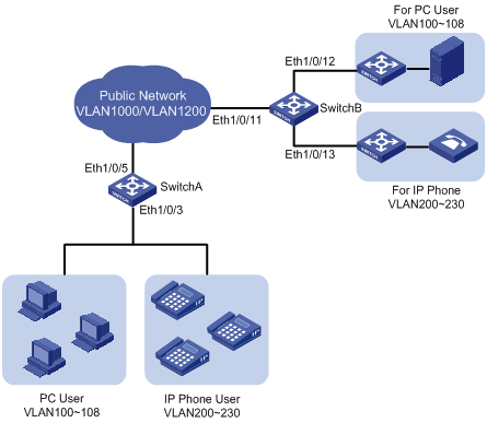
Figure 1-2 Network diagram for configuring selective qinq
Networking and Configuration Requirements
l Ethernet 1/0/3 of Switch A provides public network access for PC users and IP phone users. PC users belong to VLAN 100 through VLAN 108, and IP phone users belong to VLAN 200 through VLAN 230. Ethernet 1/0/5 of Switch A is connected to the public network. The peer end of Switch A is Switch B.
l Ethernet 1/0/11 of Switch B is connected to the public network. Ethernet 1/0/12 and Ethernet1/0/13 of Switch B provide network access for PC servers belonging to VLAN 100 through VLAN 108 and voice gateways (for IP phone users) belonging to VLAN 200 through VLAN 230 respectively.
l The public network permits packets of VLAN 1000 and VLAN 1200. Apply QoS policies for these packets to reserve bandwidth for packets of VLAN 1200. That is, packets of VLAN 1200 have higher transmission priority over packets of VLAN 1000.
l Employ the selective QinQ feature on Switch A and Switch B to differentiate traffic of PC users from that of IP phone users, for the purpose of using QoS policies to guarantee higher priority for voice traffic.
l To reduce broadcast packets in the network, enable the inter-VLAN MAC address replicating feature for selective QinQ.
Applicable Product Matrix
|
Product series |
Software version |
Hardware version |
|
S5600 series |
Release 1510, Release1602 |
All versions |
|
S5100-EI series |
Release 2200, Release2201 |
All versions |
|
S3600-SI/EI series |
Release 1510, Release1602 |
All versions |
|
S3100-EI series |
Release 2104, Release 2107 |
All versions |
|
S3100-52P |
Release 1500, Release 1602 |
S3100-52P |
![]()
Only the S5600 series, S3600-EI series, and S3100-52P switches support inter-VLAN MAC address replicating.
Configuration Procedure
l Configure Switch A.
# Create VLAN 1000, VLAN 1200 and VLAN 5 (the default VLAN of Ethernet 1/0/3) on SwitchA.
<SwitchA> system-view
[SwitchA] vlan 1000
[SwitchA-vlan1000] quit
[SwitchA] vlan 1200
[SwitchA-vlan1200] quit
[SwitchA] vlan 5
[SwitchA-vlan5] quit
# Configure Ethernet 1/0/5 as a hybrid port and configure it not to remove VLAN tags when forwarding packets of VLAN 5, VLAN 1000, and VLAN 1200.
[SwitchA] interface Ethernet 1/0/5
[SwitchA-Ethernet1/0/5] port link-type hybrid
[SwitchA-Ethernet1/0/5] port hybrid vlan 5 1000 1200 tagged
[SwitchA-Ethernet1/0/5] quit
# Configure Ethernet 1/0/3 as a hybrid port and configure VLAN 5 as its default VLAN. Configure Ethernet 1/0/3 to remove VLAN tags when forwarding packets of VLAN 5, VLAN 1000, and VLAN 1200.
[SwitchA] interface Ethernet 1/0/3
[SwitchA-Ethernet1/0/3] port link-type hybrid
[SwitchA-Ethernet1/0/3] port hybrid pvid vlan 5
[SwitchA-Ethernet1/0/3] port hybrid vlan 5 1000 1200 untagged
# Enable the VLAN-VPN feature on Ethernet 1/0/3.
[SwitchA-Ethernet1/0/3] vlan-vpn enable
# Enable the selective QinQ feature on Ethernet 1/0/3 to tag packets of VLAN 100 through VLAN 108 with the tag of VLAN 1000 as the outer VLAN tag, and tag packets of VLAN 200 through VLAN 230 with the tag of VLAN 1200 as the outer VLAN tag.
[SwitchA-Ethernet1/0/3] vlan-vpn vid 1000
[SwitchA-Ethernet1/0/3-vid-1000] raw-vlan-id inbound 100 to 108
[SwitchA-Ethernet1/0/3-vid-1000] quit
[SwitchA-Ethernet1/0/3] vlan-vpn vid 1200
[SwitchA-Ethernet1/0/3-vid-1200] raw-vlan-id inbound 200 to 230
# Enable the inter-VLAN MAC address replicating feature to replicate the MAC address entries of the MAC address tables of the outer VLANs to the MAC address table of the default VLAN, and replicate the MAC address entries of the MAC address table of the default VLAN to the MAC address tables of the outer VLANs.
[SwitchA-Ethernet1/0/3-vid-1200] quit
[SwitchA-Ethernet1/0/3] mac-address mapping 0 source-vlan 5 destination-vlan 1000
[SwitchA-Ethernet1/0/3] mac-address mapping 1 source-vlan 5 destination-vlan 1200
[SwitchA-Ethernet1/0/3] quit
[SwitchA] interface Ethernet 1/0/5
[SwitchA-Ethernet1/0/5] mac-address mapping 0 source-vlan 1000 1200 destination-vlan 5
After the above configuration, packets of VLAN 100 through VLAN 108 (that is, packets of PC users) are tagged with the tag of VLAN 1000 as the outer VLAN tag when they are forwarded to the public network by Switch A; and packets of VLAN 200 through VLAN 230 (that is, packets of IP phone users) are tagged with the tag of VLAN 1200 as the outer VLAN tag when they are forwarded to the public network.
l Configure Switch B.
# Create VLAN 1000, VLAN 1200, VLAN 12 (the default VLAN of Ethernet1/0/12) and VLAN 13 (the default VLAN of Ethernet1/0/13) on Switch B.
<SwitchB> system-view
[SwitchB] vlan 1000
[SwitchB-vlan1000] quit
[SwitchB] vlan 1200
[SwitchB-vlan1200] quit
[SwitchB] vlan 12 to 13
# Configure Ethernet 1/0/11 as a hybrid port, and configure Ethernet 1/0/11 not to remove VLAN tags when forwarding packets of VLAN 12, VLAN 13, VLAN 1000, and VLAN 1200.
<SwitchB> system-view
[SwitchB] interface Ethernet 1/0/11
[SwitchB-Ethernet1/0/11] port link-type hybrid
[SwitchB-Ethernet1/0/11] port hybrid vlan 12 13 1000 1200 tagged
# Configure Ethernet1/0/12 as a hybrid port and configure VLAN 12 as its default VLAN . Configure Ethernet 1/0/12 to remove VLAN tags when forwarding packets of VLAN 12 and VLAN 1000.
[SwitchB] interface Ethernet 1/0/12
[SwitchB-Ethernet1/0/12] port link-type hybrid
[SwitchB-Ethernet1/0/12] port hybrid pvid vlan 12
[SwitchB-Ethernet1/0/12] port hybrid vlan 12 1000 untagged
[SwitchB-Ethernet1/0/12] quit
# Configure Ethernet 1/0/13 as a hybrid port and configure VLAN 13 as its default VLAN . Configure Ethernet 1/0/13 to remove VLAN tags when forwarding packets of VLAN 13 and VLAN 1200.
[SwitchB] interface Ethernet 1/0/13
[SwitchB-Ethernet1/0/13] port link-type hybrid
[SwitchB-Ethernet1/0/13] port hybrid pvid vlan 13
[SwitchB-Ethernet1/0/13] port hybrid vlan 13 1200 untagged
After the above configuration, Switch B can forward packets of VLAN 1000 and VLAN 1200 to the corresponding servers through Ethernet 1/0/12 and Ethernet 1/0/13 respectively.
To make the packets from the servers be transmitted to the clients in the same way, you need to configure the selective QinQ feature and the inter-VLAN MAC address replicating feature on Ethernet 1/0/12 and Ethernet 1/0/13. The configuration on Switch B is similar to that on Switch A and is thus omitted.
Complete Configuration
l Configure SwitchA
#
vlan 5
#
vlan 1000
#
vlan 1200
#
interface Ethernet1/0/3
port link-type hybrid
port hybrid vlan 1 5 1000 1200 untagged
port hybrid pvid vlan 5
vlan-vpn enable
mac-address-mapping 0 source-vlan 5 destination-vlan 1000
mac-address-mapping 1 source-vlan 5 destination-vlan 1200
vlan-vpn vid 1000
raw-vlan-id inbound 100 to 108
vlan-vpn vid 1200
raw-vlan-id inbound 200 to 230
#
interface Ethernet1/0/5
port link-type hybrid
port hybrid vlan 5 1000 1200 tagged
port hybrid vlan 1 untagged
port hybrid pvid vlan 5
mac-address-mapping 0 source-vlan 1000 1200 destination-vlan 5
l Configure SwitchB
#
vlan 12 to 13
#
vlan 1000
#
vlan 1200
#
interface Ethernet1/0/11
port link-type hybrid
port hybrid vlan 12 to 13 1000 1200 tagged
port hybrid vlan 1 untagged
#
interface Ethernet1/0/12
port link-type hybrid
port hybrid vlan 1 12 1000 untagged
port hybrid pvid vlan 12
#
interface Ethernet1/0/13
port link-type hybrid
port hybrid vlan 1 13 1200 untagged
port hybrid pvid vlan 13
Precautions
l If IRF Fabric has been enabled on a device, you cannot enable the VLAN-VPN feature and the selective QinQ feature on any port of the device.
l Do not enable both the selective QinQ function and the DHCP snooping function on a switch. Otherwise, the DHCP snooping function may operate improperly.
l VLAN 4093 is a special VLAN reserved for the IRF fabric feature. It can not serve as the destination VLAN of the inter-VLAN MAC address replicating feature to receive MAC address entries from the other VLANs.
Configuring BPDU Tunnel
With the BPDU tunnel feature, a switch can transmit Layer 2 protocol packets (NDP packets in this example) along tunnels established on the public network, implementing unified network calculation and maintenance for the private networks connected through the public network.
Network Diagram
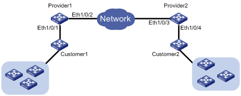
Figure 1-3 Network diagram for configuring BPDU tunnel
Networking and Configuration Requirements
l Customer 1 and Customer 2 are customer side devices, while Provider 1 and Provider 2 are edge devices of the service provider. Customer 1 and Customer 2 are connected to Ethernet 1/0/1 of Provider 1 and Ethernet 1/0/4 of Provider 2 respectively.
l Provider 1 and Provider 2 are connected through trunk a link, which permits packets of all VLANs.
l Configure the service provider network to transmit NDP packets of the customer network through a BPDU tunnel.
l Enable VLAN-VPN for the service provider network, and enable the service provider network to use VLAN 100 to transmit data packets of the customer network.
Applicable Product Matrix
|
Product series |
Software version |
Hardware version |
|
S5600 series |
Release 1510, Release 1602 |
All versions |
|
S3600-SI/EI series |
Release 1510, Release 1602 |
All versions |
|
S3100-EI series |
Release 2104, Release 2107 |
All versions |
|
S3100-52P |
Release 1500, Release 1602 |
S3100-52P |
Configuration Procedure
l Configure Provide 1.
# Disable NDP on Ethernet 1/0/1.
<Sysname> system-view
[Sysname] interface Ethernet 1/0/1
[Sysname-Ethernet1/0/1] undo ndp enable
# Enable the BPDU tunnel feature for NDP BPDUs on Ethernet 1/0/1.
[Sysname-Ethernet1/0/1] bpdu-tunnel ndp
# Enable the VLAN-VPN feature on Ethernet 1/0/1 and use VLAN 100 to tunnel user data packets.
[Sysname-Ethernet1/0/1] port access vlan 100
[Sysname-Ethernet1/0/1] vlan-vpn enable
# Configure Ethernet 1/0/2 as a trunk port that permits packets of VLAN 100.
[Sysname] interface Ethernet 1/0/2
[Sysname-Ethernet1/0/2] port link-type trunk
[Sysname-Ethernet1/0/2] port trunk permit vlan 100
l Configure Provide 2
# Disable NDP on Ethernet 1/0/4.
<Sysname> system-view
[Sysname] interface Ethernet 1/0/4
[Sysname-Ethernet1/0/4] undo ndp enable
# Enable BPDU tunnel for NDP BPDUs on Ethernet 1/0/4.
[Sysname-Ethernet1/0/4] bpdu-tunnel ndp
# Enable the VLAN-VPN feature on Ethernet 1/0/4 and use VLAN 100 to tunnel user data packets.
[Sysname-Ethernet1/0/4] port access vlan 100
[Sysname-Ethernet1/0/4] vlan-vpn enable
# Configure Ethernet 1/0/3 as a trunk port that permits packets of VLAN 100.
[Sysname] interface Ethernet 1/0/3
[Sysname-Ethernet1/0/3] port link-type trunk
[Sysname-Ethernet1/0/3] port trunk permit vlan 100
Complete Configuration
l Configure Provider 1
#
interface Ethernet1/0/1
undo ndp enable
port access vlan 100
vlan-vpn enable
bpdu-tunnel ndp
#
interface Ethernet1/0/2
port link-type trunk
port trunk permit vlan 1 100
#
l Configure Provider 2
#
interface Ethernet1/0/3
port link-type trunk
port trunk permit vlan 1 100
#
interface Ethernet1/0/4
undo ndp enable
port access vlan 100
vlan-vpn enable
bpdu-tunnel ndp
#
Precautions
l The bpdu-tunnel stp command is mutually exclusive with the vlan-vpn tunnel command configured for STP packets. Refer to MSTP in the operation manual for your switch for related information.
l The bpdu-tunnel cdp command is mutually exclusive with the voice vlan legacy command. Refer to Voice VLAN in the operation manual for your switch for related information.