- Table of Contents
-
- H3C Low-End Ethernet Switches Configuration Guide(V1.01)
- 01-Login Configuration Guide
- 02-VLAN Configuration Guide
- 03-IP Address Configuration Guide
- 04-Voice VLAN Configuration Guide
- 05-GVRP Configuration Guide
- 06-Ethernet Interface Basic Configuration Guide
- 07-Link Aggregation Configuration Guide
- 08-Port Isolation Configuration Guide
- 09-Port Security Configuration Guide
- 10-Port Binding Configuration Guide
- 11-MAC Address Table Management Configuration Guide
- 12-DLDP Configuration Guide
- 13-Auto Detect Configuration Guide
- 14-MSTP Configuration Guide
- 15-Routing Configuration Guide
- 16-Multicast Configuration Guide
- 17-802.1x Configuration Guide
- 18-AAA Configuration Guide
- 19-MAC Authentication Configuration Guide
- 20-VRRP Configuration Guide
- 21-ARP Configuration Guide
- 22-DHCP Configuration Guide
- 23-ACL Configuration Guide
- 24-QoS-QoS Profile Configuration Guide
- 25-Web Cache Redirection Configuration Guide
- 26-Mirroring Configuration Guide
- 27-IRF Configuration Guide
- 28-Cluster Configuration Guide
- 29-PoE-PoE Profile Configuration Guide
- 30-UDP Helper Configuration Guide
- 31-SNMP-RMON Configuration Guide
- 32-NTP Configuration Guide
- 33-SSH Configuration Guide
- 34-FTP and TFTP Configuration Guide
- 35-Information Center Configuration Guide
- 36-VLAN-VPN Configuration Guide
- 37-HWPing Configuration Guide
- 38-DNS Configuration Guide
- 39-Access Management Configuration Guide
- 40-Web Authentication Configuration Guide
- 41-IPv6 Management Configuration Guide
- 42-Smart link - Monitor Link Configuration Guide
- 43-VLAN Mapping Configuration Guide
- Related Documents
-
| Title | Size | Download |
|---|---|---|
| 31-SNMP-RMON Configuration Guide | 56.35 KB |
1 SNMP-RMON Configuration Guide·
Networking and Configuration Requirements
Networking and Configuration Requirements
SNMP Configuration
The Simple Network Management Protocol (SNMP) is used for ensuring the transmission of the management information between any two network nodes. In this way, network administrators can easily retrieve and modify the information about any node on the network, locate and diagnose network problems, plan for network growth, and generate reports on network nodes.
Network Diagram
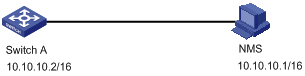
Figure 1-1 Network diagram for SNMP configuration
Networking and Configuration Requirements
l An NMS and Switch A (SNMP agent) are connected through the Ethernet. The IP address of the NMS is 10.10.10.1 and that of the VLAN interface on Switch A is 10.10.10.2.
l Perform the following configuration on Switch A: setting the community name and access right, administrator ID, contact and switch location, and enabling the switch to sent traps.
Applicable Product Matrix
|
Product series |
Software version |
Hardware version |
|
S5600 series |
Release 1510, Release1602 |
All versions |
|
S5100-SI/EI series |
Release 2200, Release2201 |
All versions |
|
S3600-SI/EI series |
Release 1510, Release1602 |
All versions |
|
S3100-EI series |
Release 2104, Release 2107 |
All versions |
|
S3100-C-SI series S3100-T-SI series |
Release 0011, Release 2102, Release 2107 |
All versions |
|
S3100-52P |
Release 1500, Release 1602 |
S3100-52P |
Configuration Procedure
Configuring the switch (SNMP agent)
# Enable SNMP agent, and set the SNMPv1 and SNMPv2c community names.
<Sysname> system-view
[Sysname] snmp-agent
[Sysname] snmp-agent sys-info version all
[Sysname] snmp-agent community read readname
[Sysname] snmp-agent community write writename
# Set the access right of the NMS to the MIB of the SNMP agent.
[Sysname] snmp-agent mib-view include internet 1.3.6.1
# For SNMPv3, set the SNMPv3 group and user, set the security level to authentication with privacy, authentication protocol to HMAC-MD5, authentication password to passmd5, encryption protocol to DES, and encryption password to cfb128cfb128.
[Sysname] snmp-agent group v3 managev3group privacy write-view internet
[Sysname] snmp-agent usm-user v3 managev3user managev3group authentication-mode md5 passmd5 privacy-mode des56 cfb128cfb128
# Configure the IP address of VLAN-interface 2 as 10.10.10.2. Add the port Ethernet 1/0/2 to VLAN 2.
[Sysname] vlan 2
[Sysname-vlan2] port Ethernet 1/0/2
[Sysname-vlan2] quit
[Sysname] interface Vlan-interface 2
[Sysname-Vlan-interface2] ip address 10.10.10.2 255.255.255.0
[Sysname-Vlan-interface2] quit
# Enable the sending of Traps to the NMS with an IP address of 10.10.10.1, using public as the community name.
[Sysname] snmp-agent trap enable standard authentication
[Sysname] snmp-agent trap enable standard coldstart
[Sysname] snmp-agent trap enable standard linkup
[Sysname] snmp-agent trap enable standard linkdown
[Sysname] snmp-agent target-host trap address udp-domain 10.10.10.1 udp-port 5000 params securityname public
Configuring the NMS
The H3C series Ethernet switches support H3C Intelligent Management Center (iMC). When you use iMC, you need to set usernames and choose the security level. For each security level, you need to set authentication mode, authentication password, privacy mode, privacy password, and so on. In addition, you need to set timeout time and maximum retry times.
You can query and configure an Ethernet switch through the NMS.
Complete Configuration
#
interface Vlan-interface2
ip address 10.10.10.2 255.255.0.0
#
interface Ethernet1/0/2
port access vlan 2
#
snmp-agent
snmp-agent local-engineid 800007DB00E0FC0000206877
snmp-agent community read readname
snmp-agent community write writename
snmp-agent sys-info version all
snmp-agent group v3 managev3group privacy write-view internet
snmp-agent target-host trap address udp-domain 10.10.10.1 udp-port 5000 params securityname public
snmp-agent mib-view included internet internet
snmp-agent usm-user v3 managev3user managev3group authentication-mode md5 passmd5 privacy-mode des56 cfb128cfb128
#
Precautions
Authentication-related configuration on an NMS must be consistent with that on the devices for the NMS to manage the devices successfully.
RMON Configuration
Remote Monitoring (RMON) is a kind of MIB defined by Internet Engineering Task Force (IETF). It is an important enhancement to MIB II standards. RMON is mainly used to monitor the data traffic across a network segment or even the entire network, and is currently a commonly used network management standard.
Network Diagram
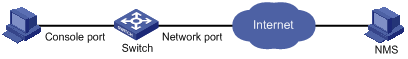
Figure 1-2 Network diagram for RMON configuration
Networking and Configuration Requirements
l Before performing RMON configuration, make sure the SNMP agents are correctly configured.
l The switch to be tested is connected to a terminal through the console port and to a remote NMS through the Internet. Create an entry in the extended alarm table to monitor the statistics on the Ethernet port. If the change rate of the entry exceeds the configured rising threshold or falling threshold, an alarm event will be triggered.
Applicable Product Matrix
|
Product series |
Software version |
Hardware version |
|
S5600 series |
Release 1510, Release1602 |
All versions |
|
S5100-SI/EI series |
Release 2200, Release2201 |
All versions |
|
S3600-SI/EI series |
Release 1510, Release1602 |
All versions |
|
S3100-EI series |
Release 2104, Release 2107 |
All versions |
|
S3100-C-SI series S3100-T-SI series |
Release 0011, Release 2102, Release 2107 |
All versions |
|
S3100-52P |
Release 1500, Release 1602 |
S3100-52P |
Configuration Procedure
# Create the statistics entry numbered 1 to take statistics on Ethernet 1/0/1.
<Sysname> system-view
[Sysname] interface Ethernet 1/0/1
[Sysname-Ethernet1/0/1] rmon statistics 1
[Sysname-Ethernet1/0/1] quit
# Add the event entries numbered 1 and 2 to the event table, which will be triggered by the following extended alarms.
[Sysname] rmon event 1 log
[Sysname] rmon event 2 trap 10.21.30.55
# Add an entry numbered 2 to the extended alarm table to allow the system to calculate the alarm variables with the (.1.3.6.1.2.1.16.1.1.1.9.1+.1.3.6.1.2.1.16.1.1.1.10.1) formula to get the numbers of all the oversize and undersize packets received by Ethernet 1/0/1 that are in correct data format and sample the numbers in every 10 seconds. When the change ratio between samples reaches the rising threshold of 50, event 1 is triggered; when the change ratio drops under the falling threshold, event 2 is triggered. Set the sampling type to forever and the owner of the alarm table to user1.
[Sysname] rmon prialarm 2 (.1.3.6.1.2.1.16.1.1.1.9.1+.1.3.6.1.2.1.16.1.1.1.10.1) test 10 changeratio rising_threshold 50 1 falling_threshold 5 2 entrytype forever owner user1
Complete Configuration
#
rmon event 1 description null log owner null
rmon event 2 description null trap 10.21.30.55 owner null
rmon prialarm 2 (.1.3.6.1.2.1.16.1.1.1.9.1+.1.3.6.1.2.1.16.1.1.1.10.1) test 10 changeratio rising_threshold 50 1 falling_threshold 5 2 entrytype forever owner user1
#
interface Ethernet1/0/1
rmon statistics 1 owner null
Precautions
None