- Table of Contents
-
- H3C Low-End Ethernet Switches Configuration Guide(V1.01)
- 01-Login Configuration Guide
- 02-VLAN Configuration Guide
- 03-IP Address Configuration Guide
- 04-Voice VLAN Configuration Guide
- 05-GVRP Configuration Guide
- 06-Ethernet Interface Basic Configuration Guide
- 07-Link Aggregation Configuration Guide
- 08-Port Isolation Configuration Guide
- 09-Port Security Configuration Guide
- 10-Port Binding Configuration Guide
- 11-MAC Address Table Management Configuration Guide
- 12-DLDP Configuration Guide
- 13-Auto Detect Configuration Guide
- 14-MSTP Configuration Guide
- 15-Routing Configuration Guide
- 16-Multicast Configuration Guide
- 17-802.1x Configuration Guide
- 18-AAA Configuration Guide
- 19-MAC Authentication Configuration Guide
- 20-VRRP Configuration Guide
- 21-ARP Configuration Guide
- 22-DHCP Configuration Guide
- 23-ACL Configuration Guide
- 24-QoS-QoS Profile Configuration Guide
- 25-Web Cache Redirection Configuration Guide
- 26-Mirroring Configuration Guide
- 27-IRF Configuration Guide
- 28-Cluster Configuration Guide
- 29-PoE-PoE Profile Configuration Guide
- 30-UDP Helper Configuration Guide
- 31-SNMP-RMON Configuration Guide
- 32-NTP Configuration Guide
- 33-SSH Configuration Guide
- 34-FTP and TFTP Configuration Guide
- 35-Information Center Configuration Guide
- 36-VLAN-VPN Configuration Guide
- 37-HWPing Configuration Guide
- 38-DNS Configuration Guide
- 39-Access Management Configuration Guide
- 40-Web Authentication Configuration Guide
- 41-IPv6 Management Configuration Guide
- 42-Smart link - Monitor Link Configuration Guide
- 43-VLAN Mapping Configuration Guide
- Related Documents
-
| Title | Size | Download |
|---|---|---|
| 27-IRF Configuration Guide | 148.81 KB |
IRF Fabric Configuration
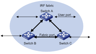
Several Intelligent Resilient Framework (IRF) supported series switches can be interconnected to form a fabric, in which each switch is a unit, the ports connecting the units are called fabric ports, and the other ports that are used to connect the fabric to users are called user ports. In this way, you can increase ports of network devices and improve the reliability of user networks.
Network Diagram
Figure 1-1 Network diagram for IRF fabric configuration
Networking and Configuration Requirements
Configure unit ID, unit name, IRF fabric name, and fabric authentication mode for three switches to enable them to form an IRF fabric.
The configuration details are as follows:
l Unit IDs for Switch A, Switch B and Switch C are 1, 2 and 3 respectively;
l Unit names of the three switches are Unit1, Unit2 and Unit3 respectively. The fabric name is hello;
l Fabric authentication mode is simple and password is welcome.
![]()
Applicable Product Matrix
|
Product series |
Software version |
Hardware version |
|
S3600-SI/EI series |
Release 1510, Release 1602 |
All versions |
|
S5600 series |
Release 1510, Release 1602 |
All versions |
Fabric Cable Connection
![]()
You are recommended to connect the switches with cables after the configuration in Configuration Procedure.
Fabric cable connection mode of S3600 switches
When building an IRF fabric of S3600 series switches, note the fabric cable connection mode:
l Multiple S3600 series switches are interconnected through their fabric ports.
l An S3600 switch has two fabric ports: left port and right port. Given a switch, its left port is connected to the right port of another switch, and its right port is connected to the left port of a third one.
![]()
On an S3600 series Ethernet switch, only four GigabitEthernet ports can be configured as fabric ports. The four ports fall into two groups according to their port numbers:
l GigabitEthernet 1/1/1 and GigabitEthernet 1/1/2 form the first group.
l GigabitEthernet 1/1/3 and GigabitEthernet 1/1/4 form the second group.
Only one group of ports can be configured as fabric ports at a time. GigabitEthernet 1/1/1 and GigabitEthernet 1/1/3 are the left fabric ports of the first and the second group respectively, and GigabitEthernet 1/1/2 and GigabitEthernet 1/1/4 are the right fabric ports or the first and the second group respectively.
An IRF fabric can be successfully built only when the fabric cables are connected in the above mode.
Based on the networking requirements in Figure 1-1, interconnect the three S3628P switches through their first group of fabric ports of as shown in the following figure:
Figure 1-2 S3600 series fabric port connection mode
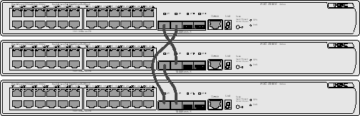
Plug out any cable shown in the above figure, and a bus connection is established.
Fabric cable connection mode of S5600 switches
When building an IRF fabric of S5600 series switches, note the fabric cable connection mode:
l Multiple S5600 series switches are interconnected through their fabric ports on their rear panels.
l An S5600 switch has two ports: up port and down port. Given a switch, its up port is connected to the down port of another switch, and its down port is connected to the up port of a third one.
l Plug the cable connectors completely into the fabric ports.
![]()
On an S5600 series Ethernet switch, only two special cascade ports can be configured as fabric ports. The two ports can only be used to form an IRF fabric, rather than function as normal ports. Their port numbers are:
l Up port: Cascade 1/2/1
l Down port: Cascade 1/2/2
An IRF fabric can be successfully built only when the fabric cables are connected in the above mode.
Based on the networking requirements in Figure 1-1, interconnect the three S5600 switches through their fabric ports as shown in the following figure:
Figure 1-3 S5600 series fabric port connection mode
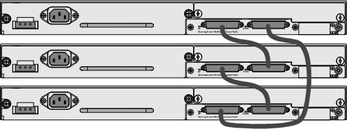
Plug out any cable shown in the above figure, and a bus connection is established.
Configuration Procedure
IRF fabric configuration on S3600 switches
1) Configure Switch A.
# Bring up the fabric ports.
<Sysname> system-view
[Sysname] fabric-port GigabitEthernet 1/1/1 enable
[Sysname] fabric-port GigabitEthernet 1/1/2 enable
# Configure the unit ID as 1.
[Sysname] change self-unit to 1
![]()
When you modify the unit ID of a switch, the switch updates its configurations automatically. The update process takes some time, during which you cannot perform any configurations on the switch. If the system generates prompts after you enter a command, wait for the update to be finished.
# Configure the unit name as Unit1.
[Sysname] set unit 1 name Unit1
# Configure the fabric name as hello.
[Sysname] sysname hello
# Configure the authentication mode as simple and password as welcome.
[hello] irf-fabric authentication-mode simple welcome
2) Configure Switch B.
# Bring up the fabric ports.
<Sysname> system-view
[Sysname] fabric-port GigabitEthernet 1/1/1 enable
[Sysname] fabric-port GigabitEthernet 1/1/2 enable
# Configure the unit ID as 2.
[Sysname] change self-unit to 2
# Configure the unit name as Unit2.
[Sysname] set unit 2 name Unit2
# Configure the fabric name as hello.
[Sysname] sysname hello
# Configure the authentication mode as simple and password as welcome.
[hello] irf-fabric authentication-mode simple welcome
Perform the same configurations on Switch C.
3) After the above configuration, use the display ftm information command to view the running status of the IRF fabric.
[hello] display ftm information
FTM State : HB STATE
Unit ID : 1 (FTM-Master)
Fabric Type : Ring
Fabric Auth : Simple
Fabric Vlan ID : 4093
Left Port : Normal
Right Port : Normal
Advertise : Send = 5, Receive = 3
Advertise ACK : Send = 0, Receive = 5
Heart Beat : Send = 20, Receive = 0
Left Port : Index = 255, IsEdge = 0
Right Port : Index = 25, IsEdge = 0
Units Num Left : 1
Units Num Right : 3
Units Num Backup: 2
By viewing the Left Port and Right Port fields in the output information, you can know the running status of the current fabric ports. The above prompt information indicates that the fabric ports are working normally (displayed as Normal).
You can also use the display irf command to view the switches in the current IRF fabric.
[hello] display irf-fabric
Fabric name is hello, system mode is L3.
Unit Name Unit ID
unit1 1(*)
unit2 2
unit3 3
You can see from the above output information that the three switches have been successfully added to the IRF fabric, and your configurations have been finished.
IRF fabric configuration on S5600 switches
1) Configure Switch A
# Bring up the fabric ports.
<Sysname> system-view
[Sysname] fabric-port Cascade 1/2/1 enable
[Sysname] fabric-port Cascade 1/2/2 enable
# Configure the unit ID as 1.
[Sysname] change self-unit to 1
# Configure the unit name as Unit1.
[Sysname] set unit 1 name Unit1
# Configure the fabric name as hello.
[Sysname] sysname hello
2) Configure Switch B.
# Bring up the fabric ports.
<Sysname> system-view
[Sysname] fabric-port Cascade 1/2/1 enable
[Sysname] fabric-port Cascade 1/2/2 enable
# Configure the unit ID as 2.
[Sysname] change self-unit to 2
# Configure the unit name as Unit2.
[Sysname] set unit 2 name Unit2
# Configure the fabric name as hello.
[Sysname] sysname hello
The configurations and verification on Switch C are the same as those on an S3600 switch. Therefore they are omitted here.
Complete Configuration
Complete configuration on S3600 switches
![]()
To avoid repetition, only the complete configuration of Switch A is listed below.
l Configuration on Switch A.
#
system-view
fabric-port GigabitEthernet 1/1/1 enable
fabric-port GigabitEthernet 1/1/2 enable
#
change unit-id 1 to 1
#
set unit 1 name Unit1
#
sysname hello
#
irf-fabric authentication-mode simple welcome
Complete configuration on S5600 switches
![]()
To avoid repetition, only the complete configuration of Switch A is listed below.
l Configurations on Switch A.
#
system-view
fabric-port Cascade 1/2/1 enable
fabric-port Cascade 1/2/2 enable
#
change unit-id 1 to 1
#
set unit 1 name Unit1
#
sysname hello
#
![]()
The change unit-id and set unit name commands will not be saved in the configuration file, that is, when you use the display current-configuration or display saved-configuration command to view the content of the configuration file, the two commands are not displayed.
Precautions
l Before configuring an IRF fabric, make sure that the software versions of each switch are the same.
l Make sure that the switches in a fabric are correctly interconnected through the fabric ports.
l Establishing an IRF system requires a high consistency of the configuration of each device. Hence, before you enable the fabric port, do not perform any configuration for the port, and do not configure some functions that affect the IRF (such as HWTACACS and VLAN-VPN) for other ports or globally. Otherwise, you cannot enable the fabric port. For detailed restrictions, refer to the error information output by devices.
l When configuring IRF, do not configure other functions, and before configuring other functions, make sure the fabric has been established and works normally.
l After a fabric is established, do not remove or plug in the cables used to form the fabric or shut down/bring up a fabric port, do not modify the unit ID of the device, and keep stability of the links between fabric ports to avoid fabric split.
l In an IRF fabric, it is required to keep the global configurations on all the fabric members consistent. If the global configurations on a switch are different from those on other switches, IRF will restart the switch forcibly and generate the same global configurations for the switch. Therefore, before building an IRF fabric, make sure the global configurations on all the switches are the same, and backup the existing configurations as needed to avoid configuration loss in case of switch restart.
l Do not modify the global configurations of any member switch when an IRF fabric is being built or the topology is unstable, so as to avoid switch restart due to global configuration inconsistency of member switches.
l If an S5600 switch with an expansion module exists in an IRF fabric, controlling the number of VLANs enhances the stability of the fabric.