- Table of Contents
-
- H3C Low-End Ethernet Switches Configuration Guide(V1.01)
- 01-Login Configuration Guide
- 02-VLAN Configuration Guide
- 03-IP Address Configuration Guide
- 04-Voice VLAN Configuration Guide
- 05-GVRP Configuration Guide
- 06-Ethernet Interface Basic Configuration Guide
- 07-Link Aggregation Configuration Guide
- 08-Port Isolation Configuration Guide
- 09-Port Security Configuration Guide
- 10-Port Binding Configuration Guide
- 11-MAC Address Table Management Configuration Guide
- 12-DLDP Configuration Guide
- 13-Auto Detect Configuration Guide
- 14-MSTP Configuration Guide
- 15-Routing Configuration Guide
- 16-Multicast Configuration Guide
- 17-802.1x Configuration Guide
- 18-AAA Configuration Guide
- 19-MAC Authentication Configuration Guide
- 20-VRRP Configuration Guide
- 21-ARP Configuration Guide
- 22-DHCP Configuration Guide
- 23-ACL Configuration Guide
- 24-QoS-QoS Profile Configuration Guide
- 25-Web Cache Redirection Configuration Guide
- 26-Mirroring Configuration Guide
- 27-IRF Configuration Guide
- 28-Cluster Configuration Guide
- 29-PoE-PoE Profile Configuration Guide
- 30-UDP Helper Configuration Guide
- 31-SNMP-RMON Configuration Guide
- 32-NTP Configuration Guide
- 33-SSH Configuration Guide
- 34-FTP and TFTP Configuration Guide
- 35-Information Center Configuration Guide
- 36-VLAN-VPN Configuration Guide
- 37-HWPing Configuration Guide
- 38-DNS Configuration Guide
- 39-Access Management Configuration Guide
- 40-Web Authentication Configuration Guide
- 41-IPv6 Management Configuration Guide
- 42-Smart link - Monitor Link Configuration Guide
- 43-VLAN Mapping Configuration Guide
- Related Documents
-
| Title | Size | Download |
|---|---|---|
| 07-Link Aggregation Configuration Guide | 46.55 KB |
Configuring Link Aggregation
Link aggregation aggregates multiple ports into one logical link, also called an aggregation group.
Link aggregation allows you to increase bandwidth by distributing incoming/outgoing traffic on the member ports in the aggregation group. In addition, it provides reliable connectivity because these member ports can dynamically back up each other.
Network Diagram
Figure 1-1 Network diagram for link aggregation configuration
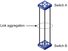
Networking and Configuration Requirements
Aggregate Ethernet 1/0/1 through 1/0/3 on Switch A into an aggregation group and connect the group to Switch B to balance incoming/outgoing traffic among the member ports.
The example will show you how to configure link aggregation in different aggregation modes.
Applicable Product Matrix
|
Product series |
Software version |
Hardware version |
|
S5600 series |
Release 1510, Release1602 |
All versions |
|
S5100-SI/EI series |
Release 2200, Release2201 |
All versions |
|
S3600-SI/EI series |
Release 1510, Release1602 |
All versions |
|
S3100-EI series |
Release 2104, Release 2107 |
All versions |
|
S3100-C-SI series S3100-T-SI series |
Release 0011, Release 2102, Release 2107 |
All versions |
|
S3100-52P |
Release 1500, Release 1602 |
S3100-52P |
Configuration Procedure
![]()
The example only provides the configuration on Switch A. Perform the same configuration on Switch B to implement link aggregation.
1) In manual aggregation mode
# Create manual aggregation group 1.
<SwitchA> system-view
[SwitchA] link-aggregation group 1 mode manual
# Add Ethernet 1/0/1 through Ethernet 1/0/3 to aggregation group 1.
[SwitchA] interface Ethernet1/0/1
[SwitchA -Ethernet1/0/1] port link-aggregation group 1
[SwitchA -Ethernet1/0/1] quit
[SwitchA] interface Ethernet1/0/2
[SwitchA -Ethernet1/0/2] port link-aggregation group 1
[SwitchA -Ethernet1/0/2] quit
[SwitchA] interface Ethernet1/0/3
[SwitchA-Ethernet1/0/3] port link-aggregation group 1
2) In static LACP aggregation mode
# Create static aggregation group 1.
<SwitchA> system-view
[SwitchA] link-aggregation group 1 mode static
# Add Ethernet 1/0/1 through Ethernet 1/0/3 to aggregation group 1.
[SwitchA] interface Ethernet1/0/1
[SwitchA-Ethernet1/0/1] port link-aggregation group 1
[SwitchA-Ethernet1/0/1] quit
[SwitchA] interface Ethernet1/0/2
[SwitchA-Ethernet1/0/2] port link-aggregation group 1
[SwitchA-Ethernet1/0/2] quit
[SwitchA] interface Ethernet1/0/3
[SwitchA-Ethernet1/0/3] port link-aggregation group 1
3) In dynamic LACP aggregation mode
# Enable LACP on Ethernet 1/0/1 through Ethernet 1/0/3.
<SwitchA> system-view
[SwitchA] interface Ethernet1/0/1
[SwitchA-Ethernet1/0/1] lacp enable
[SwitchA-Ethernet1/0/1] quit
[SwitchA] interface Ethernet1/0/2
[SwitchA-Ethernet1/0/2] lacp enable
[SwitchA-Ethernet1/0/2] quit
[SwitchA] interface Ethernet1/0/3
[SwitchA-Ethernet1/0/3] lacp enable
Complete Configuration
1) In manual aggregation mode
#
link-aggregation group 1 mode manual
#
interface Ethernet1/0/1
port link-aggregation group 1
#
interface Ethernet1/0/2
port link-aggregation group 1
#
interface Ethernet1/0/3
port link-aggregation group 1
#
2) In static LACP aggregation mode
#
link-aggregation group 1 mode static
#
interface Ethernet1/0/1
port link-aggregation group 1
#
interface Ethernet1/0/2
port link-aggregation group 1
#
interface Ethernet1/0/3
port link-aggregation group 1
#
3) In dynamic LACP aggregation mode
#
interface Ethernet1/0/1
lacp enable
#
interface Ethernet1/0/2
lacp enable
#
interface Ethernet1/0/3
lacp enable
#
Precautions
l If static LACP aggregation or manual aggregation is adopted, you are recommended not to cross-connect the aggregation member ports at the two ends to avoid packet loss. For example, if local port 1 is connected to remote port 2, do not connect local port 2 to remote port 1.
l Dynamic LACP aggregation mode is not recommended in actual networking scenarios.
l The implementation of static aggregation varies by platform software version. This may result in problems when products using different platform software versions are interconnected through static aggregation groups. Use the display version command to view the platform software version.
l the S3100-SI series only supports manually-configured aggregation groups.