- Table of Contents
-
- H3C MSR5680-X3 Router Configuration Examples All-in-One-R9141-6W100
- 00-Preface
- 01-AAA Configuration Examples
- 02-ACL Configuration Examples
- 03-MPLS over ADVPN Configuration Examples
- 04-ARP Attack Protection Configuration Examples
- 05-BFD Configuration Examples
- 06-Basic BGP Configuration Examples
- 07-BGP Route Attribute-Based Route Selection Configuration Examples
- 08-EAA Monitor Policy Configuration Examples
- 09-GRE with OSPF Configuration Examples
- 10-HoVPN Configuration Examples
- 11-IGMP Configuration Examples
- 12-IPsec Configuration Examples
- 13-IPsec Digital Certificate Authentication Configuration Examples
- 14-IPv6 IS-IS Configuration Examples
- 15-IPv6 over IPv4 GRE Tunnel Configuration Examples
- 16-IPv6 over IPv4 Manual Tunnel with OSPFv3 Configuration Examples
- 17-IS-IS Configuration Examples
- 18-Combined ISATAP Tunnel and 6to4 Tunnel Configuration Examples
- 19-L2TP over IPsec Configuration Examples
- 20-Multi-Instance L2TP Configuration Examples
- 21-L2TP Multidomain Access Configuration Examples
- 22-MPLS L3VPN Configuration Examples
- 23-MPLS OAM Configuration Examples
- 24-MPLS TE Configuration Examples
- 25-Basic MPLS Configuration Examples
- 26-NAT DNS Mapping Configuration Examples
- 27-NetStream Configuration Examples
- 28-NQA Configuration Examples
- 29-NTP Configuration Examples
- 30-OSPFv3 Configuration Examples
- 31-OSPF Configuration Examples
- 32-OSPF Multi-Process Configuration Examples
- 33-OSPF Multi-Instance Configuration Examples
- 34-Portal Configuration Examples
- 35-POS Interace Configuration Examples
- 36-PPP Configuration Examples
- 37-RBAC Configuration Examples
- 38-RMON Configuration Examples
- 39-IPv4 NetStream Sampling Configuration Examples
- 40-SNMP Configuration Examples
- 41-SRv6 Configuration Examples
- 42-SSH Configuration Examples
- 43-Tcl Commands Configuration Examples
- 44-VLAN Configuration Examples
- 45-VRRP Configuration Examples
- 46-VXLAN over IPsec Configuration Examples
- 47-Cloudnet VPN Configuration Examples
- 48-Ethernet Link Aggregation Configuration Examples
- 49-Ethernet OAM Configuration Examples
- 50-Outbound Bidirectional NAT Configuration Examples
- 51-NAT Hairpin in C-S Mode Configuration Examples
- 52-Load Sharing NAT Server Configuration Examples
- 53-BIDIR-PIM Configuration Examples
- 54-Control Plane-Based QoS Policy Configuration Examples
- 55-Scheduling a Task Configuration Examples
- 56-Client-Initiated L2TP Tunnel Configuration Examples
- 57-LAC-Auto-Initiated L2TP Tunnel Configuration Examples
- 58-Authorized ARP Configuration Examples
- 59-GTS Configuration Examples
- 60-Traffic Policing Configuration Examples
- 61-Traffic Accounting Configuration Examples
- 62-PBR Configuration Examples
- 63-TFTP Client Software Upgrade Configuration Examples
- 64-FTP Client Software Upgrade Configuration Examples
- 65-FTP Server Software Upgrade Configuration Examples
- 66-Routing Policy Configuration Examples
- 67-Software Upgrade from the BootWare Menu Configuration Examples
- 68-Mirroring Configuration Examples
- Related Documents
-
| Title | Size | Download |
|---|---|---|
| 37-RBAC Configuration Examples | 361.04 KB |
H3C Routers
RBAC Configuration Examples
Copyright © 2024 New H3C Technologies Co., Ltd. All rights reserved.
Without written permission from our company, no individual or organization may illegally extract, copy, or propagate any part or all of the content of this document in any way.
Except for the trademarks of New H3C Technologies Co., Ltd., any trademarks that may be mentioned in this document are the property of their respective owners.
The information in this document is subject to change without notice.
Contents
Example: Configuring read and write permissions for specific features
Example: Configuring authorization for Telnet users of the RADIUS user role
Example: Configuring user permissions in specific VPNs
Example: Modifying user permissions by creating and authorizing a new user role
Verifying user permission before the permission change
Verifying user permission after the permission change
Example: Configuring users with the permission to switch between user roles
Example: Configuring the flow control permission
Overview
This document presents a typical example of using RBAC to control user authority on login devices.
Prerequisites
The following information applies to Comware 9-based routers. Procedures and information in the examples might be slightly different depending on the software or hardware version of the router.
The configuration examples in this document were created and verified in a lab environment, and all the devices were started with the factory default configuration. When you are working on a live network, make sure you understand the potential impact of every command on your network.
The following information is provided based on the assumption that you have basic knowledge of RBAC.
Example: Configuring read and write permissions for specific features
Network configuration
As shown in Figure 1, to enhance security of user logins, local AAA authentication is used to authenticate Telnet users on the device. Give Telnet users the following permissions:
· Allow execution of all read and write type commands related to OSPF.
· Allow execution of all read-write commands related to file system.

Analysis
· For a Telnet user to have the permissions, create a local Telnet user and user role role1, then, grant the Telnet users with the user role.
· Configure user role rules to limit Telnet users to execute read and write commands related to OSPF and file system.
· To ensure that Telnet users only use the authorized user role, delete the default user role assigned to the user.
Software versions used
This configuration example was created and verified on R9141P16 of the MSR5680-X3 device.
Restrictions and guidelines
· After configuring an ISP domain as the default one, you cannot delete the domain. To delete the domain, you must first use the undo domain default enable command to change the domain to a non-default domain.
· One user role can create multiple rules, each identified by a unique number. Users authorized with this role can execute commands defined by the executable command union of these rules. If the permissions defined by two rules have conflicts, the rule with a higher number takes effect. For example, rule 1 allows executing command A, rule 2 allows executing command B, and rule 3 prohibits executing command A. Thus, rules 2 and 3 take effect, meaning command A is prohibited and command B is allowed.
Procedures
1. Configure interfaces.
# Configure an IP address for interface GigabitEthernet1/0/1.
<Router> system-view
[Router] interface gigabitethernet 1/0/1
[Router-GigabitEthernet1/0/1] ip address 192.168.1.50 24
[Router-GigabitEthernet1/0/1] quit
2. Configure the authentication method for Telnet user login.
# Activate the Telnet server function on the device.
[Router] telnet server enable
# Configure Telnet user login with the AAA authentication method on VTY user lines numbered from 0 to 63.
[Router] line vty 0 63
[Router-line-vty0-63] authentication-mode scheme
The command is "quit" on line vty0-63 of the system.
3. Configure the AAA method for an ISP domain.
# Create ISP domain bbb and authorize login users with local authentication and authorization.
[Router] domain bbb
[Router-isp-bbb] authentication login local
[Router-isp-bbb] authorization login local
[Router-isp-bbb] quit
4. Configure the password and service type for local user telnetuser.
# Create a local device management user named telnetuser.
[Router] local-user telnetuser class manage
# Set a plaintext password 123456TESTplat&!.
[Router-luser-manage-telnetuser] password simple 123456TESTplat&!
# Specify the service type as Telnet.
[Router-luser-manage-telnetuser] service-type telnet
[Router-luser-manage-telnetuser] quit
5. Create user role role1 and configure its rules.
# Create user role role1 and enter its view.
[Router] role name role1
# Configure user role rule 1 to allow executing all commands of the read-write type related to OSPF.
[Router-role-role1] rule 1 permit read write feature ospf
# Configure user role rule 2 to allow executing all commands of the read-write type related to file system.
[Router-role-role1] rule 2 permit read write feature filesystem
[Router-role-role1] quit
6. Configure the authorized user role for the local user.
# Enter view of local user telnetuser.
[Router] local-user telnetuser class manage
# Authorize user telnetuser with role role1.
[Router-luser-manage-telnetuser] authorization-attribute user-role role1
# For the user to use only the authorized user role, delete the default user role network-operator.
[Router-luser-manage-telnetuser] undo authorization-attribute user-role network-operator
[Router-luser-manage-telnetuser] quit
[Router] quit
Verifying the configuration
1. View user role information.
# Use the display role command to view the information about user role role1.
<Router> display role name role1
Role: role1
Description:
VLAN policy: permit (default)
Interface policy: permit (default)
VPN instance policy: permit (default)
Security zone policy: permit (default)
-------------------------------------------------------------------
Rule Perm Type Scope Entity
-------------------------------------------------------------------
1 permit RW- feature ospf
2 permit RW- feature filesystem
R:Read W:Write X:Execute
2. Make the user log in to the device.
Make the user initiate a Telnet connection to the device and enter user name telnetuser@bbb and the correct password at the prompt. Verify that you can log in to the device.
C:\Documents and Settings\user> telnet 192.168.1.50
******************************************************************************
* Copyright (c) 2004-2023 Hangzhou H3C Tech. Co., Ltd. All rights reserved. *
* Without the owner's prior written consent, *
* no decompiling or reverse-engineering shall be allowed. *
******************************************************************************
login: telnetuser@bbb
Password:
<Router>
3. Verify the user permissions.
After the Telnet user logs in to the device, perform the following tasks to verify the user permissions:
¡ Execute write commands of OSPF. (This section uses OSPF configuration as an example.)
[Router] ospf 1
[Router-ospf-1] area 0
[Router-ospf-1-area-0.0.0.0] network 1.1.1.1 0.0.0.0
[Router-ospf-1-area-0.0.0.0] quit
[Router-ospf-1] quit
¡ Execute read command of OSPF.
[Router] show ospf
OSPF Process 1 with Router ID 192.168.1.50
OSPF Protocol Information
RouterID: 192.168.1.50 Router type:
Route tag: 0
Multi-VPN-Instance is not enabled
Ext-community type: Domain ID 0x5, Route Type 0x306, Router ID 0x107
Domain ID: 0.0.0.0
Opaque capable
Isolation: Disabled
ISPF is enabled
SPF-schedule-interval: 5 50 200
LSA generation interval: 5 50 200
LSA arrival interval: 1000
Transmit pacing: Interval: 20 Count: 3
Default ASE parameters: Metric: 1 Tag: 1 Type: 2
Route preference: 10
ASE route preference: 150
SPF calculation count: 0
RFC 1583 compatible
Fast-reroute: Remote-lfa Disabled
Maximum-cost: 4294967295
Node-Protecing Preference: 40
Lowest-cost Preference: 20
Graceful restart interval: 120
SNMP trap rate limit interval: 10 Count: 7
Area count: 1 NSSA area count: 0
ExChange/Loading neighbors: 0
MPLS segment routing: Disabled
Segment routing adjacency : Disabled
Effective SRGB : 16000 24000
Segment routing local block : 15000 15999
Segment routing tunnel count: 0
Area: 0.0.0.0 (MPLS TE not enabled)
Authentication type: None Area flag: Normal
SPF scheduled count: 0
ExChange/Loading neighbors: 0
¡ Execute the read and write commands of file system. (This section configures the source IP address of FTP packets as an example.)
[Router] ftp client source ip 192.168.0.60
[Router] quit
¡ Verify that you cannot execute commands of the execution type related to filesystem. (This section attempts to enter FTP view as an example.)
<Router> ftp
Permission denied.
Configuration files
#
telnet server enable
#
interface GigabitEthernet1/0/1
ip address 192.168.1.50 24
#
line vty 0 63
authentication-mode scheme
user-role network-operator
#
domain bbb
authentication login local
authorization login local
#
role name role1
rule 1 permit read write feature ospf
rule 2 permit read write feature filesystem
#
local-user telnetuser class manage
password hash $h$6$kZw1rKFsAY4lhgUz$+teVLy8gmKN4Mr00VWgXQTB8ai94gKHlrys5OkytGf4
kT+nz5X1ZGASjc282CYAR6A1upH2jbmRoTcfDzZ9Gmw==
service-type telnet
authorization-attribute user-role role1
#
Example: Configuring authorization for Telnet users of the RADIUS user role
Network configuration
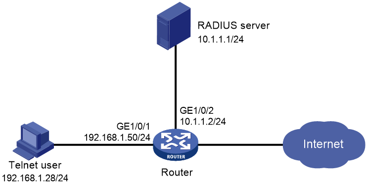
As shown in Figure 2, the Telnet user's host is connected to the device, and the device is connected to a RADIUS server. Configure the RADIUS server authenticate and authorize Telnet users logging into the device, so that the Telnet users can obtain the following user permissions:
· Allow users to execute all commands in ISP view.
· Allow users to execute read and write commands for ARP and RADIUS.
· Allow users to execute commands related to VLAN creation and commands in VLAN view and allow users to configure only VLANs 10 through 20.
· Allow users to access interface view and execute commands in interface view, and allow users to configure interfaces GigabitEthernet 1/0/1 through GigabitEthernet 1/0/3.
Analysis
· For Telnet users to execute read and write commands for ARP and RADIUS, create a feature group named feature-group1 and add ARP and RADIUS to the group.
· To authorize Telnet users to execute requested commands, configure corresponding user role rules and resource control policies.
· To grant Telnet users the permissions, authorize user role role1 on the RADIUS server.
Software versions used
This configuration example was created and verified on R9141P16 of the MSR5680-X3 device.
Restrictions and guidelines
1. After configuring an ISP domain as the default one, you cannot delete the domain. To delete the domain, you must first use the undo domain default enable command to change the domain to a non-default domain.
2. The authorization information from the RADIUS server is sent to the RADIUS client with the authentication response message. Make sure the authentication and authorization methods are the same.
3. One user role can create multiple rules, each identified by a unique number. Users authorized with this role can execute commands defined by the executable command union of these rules. If the permissions defined by two rules have conflicts, the rule with a higher number takes effect. For example, rule 1 allows executing command A, rule 2 allows executing command B, and rule 3 prohibits executing command A. Thus, rules 2 and 3 take effect, meaning command A is prohibited and command B is allowed.
Procedures
Configuring the device
1. Configure interfaces and routes.
# Configure the IP address of interface GigabitEthernet1/0/1. Users will use this address to connect to the device through Telnet.
<Router> system-view
[Router] interface gigabitethernet 1/0/1
[Router-GigabitEthernet1/0/1] ip address 192.168.1.50 255.255.255.0
[Router-GigabitEthernet1/0/1] quit
# Configure the IP address of interface GigabitEthernet1/0/2. Devices will use this address to communicate with the server.
[Router] interface gigabitethernet 1/0/2
[Router-GigabitEthernet1/0/2] ip address 10.1.1.2 255.255.255.0
[Router-GigabitEthernet1/0/2] quit
# Configure a default route for Telnet users to reach the RADIUS server.
[Router] ip route-static 0.0.0.0 0.0.0.0 10.1.1.1
2. Configure the authentication method for Telnet user login.
# Activate the Telnet server function on the device.
[Router] telnet server enable
# Configure the AAA authentication method used for Telnet user login.
[Router] line vty 0 63
[Router-line-vty0-63] authentication-mode scheme
[Router-line-vty0-63] quit
3. Configure the RADIUS scheme and authentication server.
# Create RADIUS scheme rad.
[Router] radius scheme rad
# Configure the IP address of the primary authentication/authorization server as 10.1.1.1 and the primary accounting server as 10.1.1.1.
[Router-radius-rad] primary authentication 10.1.1.1
[Router-radius-rad] primary accounting 10.1.1.1
# Set the shared key for interaction messages with the authentication/authorization server and the primary accounting server as plaintext aabbcc.
[Router-radius-rad] key authentication simple aabbcc
[Router-radius-rad] key accounting simple aabbcc
[Router-radius-rad] quit
4. Configure the AAA method for an ISP domain.
# Create ISP domain bbb and configure login users to use the RADIUS authentication, RADIUS authorization, and RADIUS accounting AAA methods.
[Router] domain bbb
[Router-isp-bbb] authentication login radius-scheme rad
[Router-isp-bbb] authorization login radius-scheme rad
[Router-isp-bbb] accounting login radius-scheme rad
[Router-isp-bbb] quit
5. Configure the feature group.
# Create feature group group1.
[Router] role feature-group name fgroup1
# Add ARP and RADIUS to the feature group.
[Router-featuregrp-fgroup1] feature arp
[Router-featuregrp-fgroup1] feature radius
[Router-featuregrp-fgroup1] quit
6. Create user role role1 and configure rules and resource control policies for the user role.
# Create user role role1.
[Router] role name role1
# Configure user role rule 1 to allow users to execute all commands in ISP view.
[Router-role-role1] rule 1 permit command system-view ; domain *
# Configure user role rule 2 to allow users to execute read and write commands of all features in feature group fgroup1.
[Router-role-role1] rule 2 permit read write feature-group fgroup1
# Configure user role rule 3 to allow users to execute VLAN creation commands.
[Router-role-role1] rule 3 permit command system-view ; vlan *
# Configure user role rule 4 to allow users to access interface view and execute commands in interface view.
[Router-role-role1] rule 4 permit command system-view ; interface *
# Enter VLAN policy view and allow users to have permissions to manage VLANs 10 through 20.
[Router-role-role1] vlan policy deny
[Router-role-role1-vlanpolicy] permit vlan 10 to 20
[Router-role-role1-vlanpolicy] quit
# Enter interface policy view, and allow users to have permissions to manage interfaces GigabitEthernet 1/0/1 through GigabitEthernet 1/0/3.
[Router-role-role1] interface policy deny
[Router-role-role1-ifpolicy] permit interface gigabitethernet 1/0/1 to gigabitethernet 1/0/3
[Router-role-role1-ifpolicy] quit
[Router-role-role1] quit
Configuring the RADIUS server
|
|
NOTE: This section uses iMC PLAT 7.0 (E0202) and iMC UAM 7.0 (E0202) as an example to illustrate basic configuration of the RADIUS server. |
1. Add an access device.
Log in to the IMC management platform, click the User tab, and select User Access Policy > Access Device Management > Access Device in the left navigation pane. Then, click Add.
¡ Specify the authentication and accounting port numbers to 1812 and 1813, respectively.
¡ Set the shared key for authentication and accounting for AC interaction messages as aabbcc and confirm the shared key.
¡ Select Device Management Service as the service type.
¡ Select H3C (General) as the access device type.
¡ Select or manually add the device with IP address 10.1.1.2 as an access device.
¡ Retain the default settings in the other fields and then click OK.
2. Add a device management user.
Click the User tab, and select Device User > Device User in the navigation pane. Click Add.
¡ Specify the user name, set the password, and confirm the password. In this example, the username is telnetuser@bbb.
¡ Select Telnet as the service type.
¡ Add user role role1.
¡ Add IP addresses of devices to be managed. In this example, the IP address range is 10.1.1.0 to 10.1.1.10.
¡ Click OK.
Verifying the configuration
1. View user role and feature group information.
# Use the display role command to view user role information.
<Router> display role name role1
Role: role1
Description:
VLAN policy: deny
Permitted VLANs: 10 to 20
Interface policy: deny
Permitted interfaces: GigabitEthernet1/0/1 to GigabitEthernet1/0/3
VPN instance policy: permit (default)
Security zone policy: permit (default)
-------------------------------------------------------------------
Rule Perm Type Scope Entity
-------------------------------------------------------------------
1 permit command system-view ; domain *
2 permit RW- feature-group fgroup1
3 permit command system-view ; vlan *
4 permit command system-view ; interface *
R:Read W:Write X:Execute
2. Make the user log in to the device.
Make the user initiate a Telnet connection to the device and enter user name telnetuser@bbb and the correct password at the prompt. Verify that you can log in to the device.
C:\Documents and Settings\user> telnet 192.168.1.50
******************************************************************************
* Copyright (c) 2004-2023 Hangzhou H3C Tech. Co., Ltd. All rights reserved. *
* Without the owner's prior written consent, *
* no decompiling or reverse-engineering shall be allowed. *
******************************************************************************
login: telnetuser@bbb
Password:
<Router>
3. Verify the user permissions.
After the Telnet user logs in to the device, perform the following tasks to verify the user permissions:
¡ Execute commands in ISP view.
<Router> system-view
[Router] domain abc
[Router-isp-abc] authentication login radius-scheme abc
[Router-isp-abc] quit
¡ Execute read and write commands of the RADIUS feature. (Same as the verifying permissions over the ARP feature.)
[Router] radius scheme rad
[Router-radius-rad] primary authentication 2.2.2.2
[Router-radius-rad] display radius scheme rad
¡ Verify that you can manage only VLAN 10 through VLAN 20. (This section creates VLAN 10 and VLAN 30 as an example.)
[Router] vlan 10
[Router-vlan10] quit
[Router] vlan 30
Permission denied.
¡ Verify that you can manage only interfaces GigabitEthernet 1/0/1 through GigabitEthernet 1/0/3. (This section uses interface GigabitEthernet 1/0/1 as an example.)
[Router] interface gigabitethernet 1/0/1
[Router-GigabitEthernet1/0/1] ip address 1.1.1.1 24
[Router-GigabitEthernet1/0/1] quit
¡ Verify that you cannot manage other interfaces. (This section enters interface view of Ten-GigabitEthernet 0/0/9 as an example.)
[Router] interface gigabitethernet 1/0/4
Permission denied.
Configuration files
#
telnet server enable
#
interface GigabitEthernet1/0/1
ip address 192.168.1.50 24
#
interface GigabitEthernet1/0/2
ip address 10.1.1.2 24
#
line vty 0 63
authentication-mode scheme
user-role network-operator
#
ip route-static 0.0.0.0 0 10.1.1.1
#
radius scheme rad
primary authentication 10.1.1.1
primary accounting 10.1.1.1
key authentication cipher $c$3$JzDegvL0G5KZIcJhzscTHLA4WasBVh0UOw==
key accounting cipher $c$3$CdejNYYxvjW0Y+Zydi4rZgBwjYb4h6LKmg==
#
domain bbb
authentication login radius-scheme rad
authorization login radius-scheme rad
accounting login radius-scheme rad
#
role feature-group name fgroup1
feature arp
feature radius
#
role name role1
rule 1 permit command system-view ; domain *
rule 2 permit read write feature-group fgroup1
rule 3 permit command system-view ; vlan *
rule 4 permit command system-view ; interface *
vlan policy deny
permit vlan 10 to 20
interface policy deny
permit interface GigabitEthernet1/0/1 to GigabitEthernet1/0/3
#
Example: Configuring user permissions in specific VPNs
Network configuration
As shown in Figure 3, in order to enhance the security of user login, RADIUS server is used to authenticate and authorize Telnet users, granting them the following permissions:
· Allow the execution of all commands related to predefined feature group L3 in the system.
· Allow the execution of all commands starting with the display keyword.
· Allow management only of specific VPN instances, for example, VPN instances vpn1, vpn2, and vpn3.

Analysis
· To authorize Telnet users to execute requested commands, create user role role1 and configure the user role rules and resource control policies.
· To grant Telnet users the permissions, authorize user role role1 on the RADIUS server.
Software versions used
This configuration example was created and verified on R9141P16 of the MSR5680-X3 device.
Restrictions and guidelines
1. After configuring an ISP domain as the default one, you cannot delete the domain. To delete the domain, you must first use the undo domain default enable command to change the domain to a non-default domain.
2. The authorization information from the RADIUS server is sent to the RADIUS client with the authentication response message. Make sure the authentication and authorization methods are the same.
3. One user role can create multiple rules, each identified by a unique number. Users authorized with this role can execute commands defined by the executable command union of these rules. If the permissions defined by two rules have conflicts, the rule with a higher number takes effect. For example, rule 1 allows executing command A, rule 2 allows executing command B, and rule 3 prohibits executing command A. Thus, rules 2 and 3 take effect, meaning command A is prohibited and command B is allowed.
Procedures
Device Configuration
1. Configure interfaces and routes.
# Configure an IP address for interface GigabitEthernet1/0/1.
<Router> system-view
[Router] interface gigabitethernet 1/0/1
[Router-GigabitEthernet1/0/1] ip address 192.168.1.50 24
[Router-GigabitEthernet1/0/1] quit
# Configure an IP address for interface GigabitEthernet1/0/2.
[Router] interface gigabitethernet 1/0/2
[Router-GigabitEthernet1/0/2] ip address 10.1.1.2 24
[Router-GigabitEthernet1/0/2] quit
# Configure a default route for Telnet users to reach the RADIUS server.
[Router] ip route-static 0.0.0.0 0.0.0.0 10.1.1.1
2. Configure the authentication method for Telnet user login.
# Activate the Telnet server function on the device.
[Router] telnet server enable
# Configure Telnet user login with the AAA authentication method on VTY user lines numbered from 0 to 63.
[Router] line vty 0 63
[Router-line-vty0-63] authentication-mode scheme
[Router-line-vty0-63] quit
3. Configure the RADIUS scheme and authentication server.
# Create RADIUS scheme rad.
[Router] radius scheme rad
# Configure the IP address of the primary authentication/authorization server as 10.1.1.1 and the primary accounting server as 10.1.1.1.
[Router-radius-rad] primary authentication 10.1.1.1
[Router-radius-rad] primary accounting 10.1.1.1
# Set the shared key for interaction messages with the authentication/authorization server and the primary accounting server as plaintext aabbcc.
[Router-radius-rad] key authentication simple aabbcc
[Router-radius-rad] key accounting simple aabbcc
[Router-radius-rad] quit
4. Configure the AAA method for an ISP domain.
# Create ISP domain bbb and configure login users to use the RADIUS authentication, RADIUS authorization, and RADIUS accounting AAA methods.
[Router] domain bbb
[Router-isp-bbb] authentication login radius-scheme rad
[Router-isp-bbb] authorization login radius-scheme rad
[Router-isp-bbb] accounting login radius-scheme rad
[Router-isp-bbb] quit
5. Create user role role1 and configure rules and resource control policies for the user role.
# Create user role role1 and enter its view.
[Router] role name role1
# Configure user role rule 1 to allow users to execute all commands related to predefined feature group L3.
[Router-role-role1] rule 1 permit execute read write feature-group L3
# Configure user role rule 2 to allow users to execute all commands starting with the display keyword.
[Router-role-role1] rule 2 permit command display *
# Enter user role VPN policy view and authorize users with the permission to manage VPN instances vpn1, vpn2, and vpn3.
[Router-role-role1] vpn-instance policy deny
[Router-role-role1-vpnpolicy] permit vpn-instance vpn1 vpn2 vpn3
[Router-role-role1-vpnpolicy] quit
[Router-role-role1] quit
[Router] quit
Configuring the RADIUS server
|
|
NOTE: This section uses iMC PLAT 7.0 (E0202) and iMC UAM 7.0 (E0202) as an example to illustrate basic configuration of the RADIUS server. |
1. Add an access device.
Log in to the IMC management platform, click the User tab. In the left navigation pane, select User Access Policy > Access Device Management > Access Device. Click Add.
¡ Specify the authentication and accounting port numbers to 1812 and 1813, respectively.
¡ Set the shared key for authentication and accounting for AC interaction messages as aabbcc and confirm the shared key.
¡ Select Device Management Service as the service type.
¡ Select H3C (General) as the access device type.
¡ Select or manually add the device with IP address 10.1.1.2 as an access device.
¡ Retain the default settings in the other fields and then click OK.
2. Add a device management user.
Click the User tab, and select Device User > Device User in the navigation pane. Click Add.
¡ Specify the user name, set the password, and confirm the password. In this example, the username is telnetuser@bbb.
¡ Select Telnet as the service type.
¡ Add user role role1.
¡ Add IP addresses of devices to be managed. In this example, the IP address range is 10.1.1.0 to 10.1.1.10.
¡ Click OK.
Verifying the configuration
1. View user role and feature group information.
# Use the display role command to view user role information.
<Router> display role name role1
Role: role1
Description:
VLAN policy: permit (default)
Interface policy: permit (default)
VPN instance policy: deny
Permitted VPN instances: vpn1, vpn2, vpn3
Security zone policy: permit (default)
-------------------------------------------------------------------
Rule Perm Type Scope Entity
-------------------------------------------------------------------
1 permit RWX feature-group L3
2 permit command display *
R:Read W:Write X:Execute
Use the display role feature-group command to view feature information in feature group L3. (Details not shown.)
2. Make the user log in to the device.
Make the user initiate a Telnet connection to the device and enter user name telnetuser@bbb and the correct password at the prompt. Verify that you can log in to the device.
C:\Documents and Settings\user> telnet 192.168.1.50
******************************************************************************
* Copyright (c) 2004-2023 Hangzhou H3C Tech. Co., Ltd. All rights reserved. *
* Without the owner's prior written consent, *
* no decompiling or reverse-engineering shall be allowed. *
******************************************************************************
login: telnetuser@bbb
Password:
<Router>
3. Verify the user permissions.
After the Telnet user logs in to the device, perform the following tasks to verify the user permissions:
¡ Execute commands in the predefined feature group L3. (This section creates VPN instance vpn1 and set the RD to 22:1 as an example.)
<Router> system-view
[Router] ip vpn-instance vpn1
[Router-vpn-instance-vpn1] route-distinguisher 22:1
[Router-vpn-instance-vpn1] display this
#
ip vpn-instance vpn1
route-distinguisher 22:1
#
return
[Router-vpn-instance-vpn1] quit
¡ Verify that you cannot manage other VPN instances. (This section uses VPN instance vpn5 as an example.)
[Router] ip vpn-instance vpn5
Permission denied.
Configuration files
#
telnet server enable
#
interface GigabitEthernet1/0/1
ip address 192.168.1.50 24
#
interface GigabitEthernet1/0/2
ip address 10.1.1.2 24
#
line vty 0 63
authentication-mode scheme
user-role network-operator
#
ip route-static 0.0.0.0 0 10.1.1.1
#
radius scheme rad
primary authentication 10.1.1.1
primary accounting 10.1.1.1
key authentication cipher $c$3$JzDegvL0G5KZIcJhzscTHLA4WasBVh0UOw==
key accounting cipher $c$3$CdejNYYxvjW0Y+Zydi4rZgBwjYb4h6LKmg==
#
domain bbb
authentication login radius-scheme rad
authorization login radius-scheme rad
accounting login radius-scheme rad
#
role name role1
rule 1 permit read write execute feature-group L3
rule 2 permit command display *
vpn-instance policy deny
permit vpn-instance vpn1
permit vpn-instance vpn2
permit vpn-instance vpn3
#
Example: Modifying user permissions by creating and authorizing a new user role
Network configuration
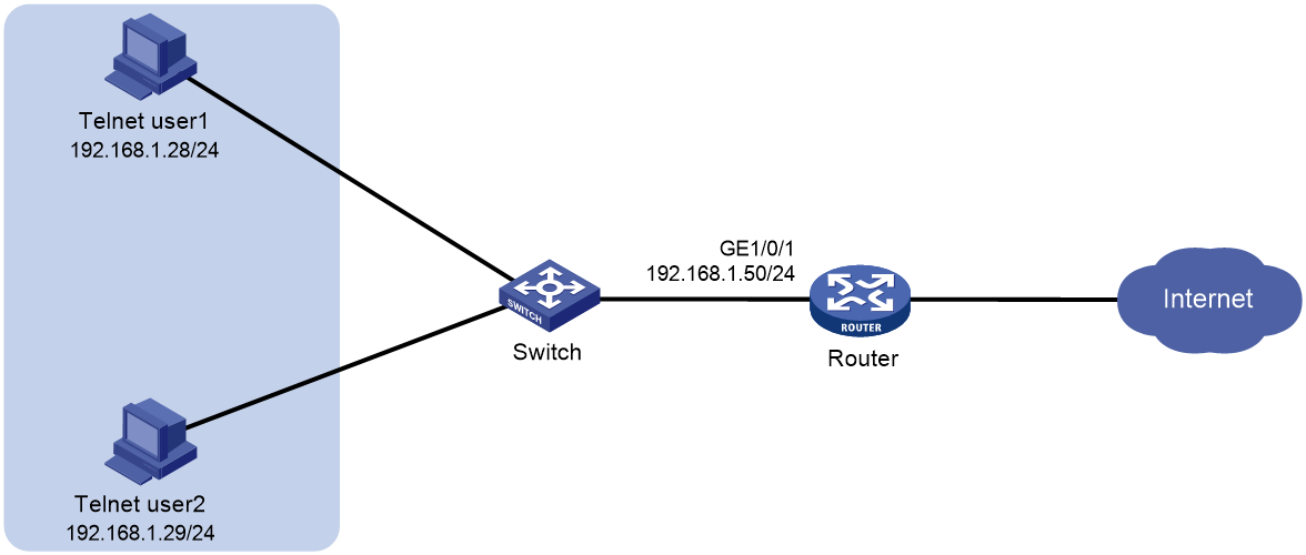
As shown in Figure 4, to enhance security of user logins, local AAA authentication is used to authenticate Telnet users on the device. Telnet users telnetuser1 and telnetuser2 use ISP domain bbb to access the network. After successfully logging in to the devices, both users are assigned user role role1, which has the following permissions:
· Allow the execution of all commands starting with the display keyword.
· Allow the execution of the command to create VLANs.
· Allow users to manage only VLAN 10 through VLAN 15.
· Allow users to manage only GigabitEthernet 1/0/1.
The following permissions need to be added to Telnet user telnetuser1:
· Allow management of VLAN 16 through VLAN 20.
· Allow management of interfaces GigabitEthernet 1/0/2 and GigabitEthernet 1/0/3.
Analysis
· To grant Telnet user telnetuser1 permissions without changing the permissions of Telnet user telnetuser2, create user role role2 and assign it to Telnet user telnetuser1.
· To enable Telnet user telnetuser1 to execute required commands, configure user role rules and resource control policies.
Software versions used
This configuration example was created and verified on R9141P16 of the MSR5680-X3 device.
Restrictions and guidelines
· One user role can create multiple rules, each identified by a unique number. Users authorized with this role can execute commands defined by the executable command union of these rules. If the permissions defined by two rules have conflicts, the rule with a higher number takes effect. For example, rule 1 allows executing command A, rule 2 allows executing command B, and rule 3 prohibits executing command A. Thus, rules 2 and 3 take effect, meaning command A is prohibited and command B is allowed.
· You can authorize a user with multiple user roles. Users with multiple roles can access a set of functions and resources allowed by each role they have.
· If you authorize a new role to an online user, the new role takes effect after the user comes online again.
Procedures
1. Configure interfaces.
# Configure an IP address for interface GigabitEthernet1/0/1.
<Router> system-view
[Router] interface gigabitethernet 1/0/1
[Router-GigabitEthernet1/0/1] ip address 192.168.1.50 24
[Router-GigabitEthernet1/0/1] quit
2. Configure the authentication method for Telnet user login.
# Activate the Telnet server function on the device.
[Router] telnet server enable
# Configure Telnet user login with the AAA authentication method on VTY user lines numbered from 0 to 63.
[Router] line vty 0 63
[Router-line-vty0-63] authentication-mode scheme
[Router-line-vty0-63] quit
3. Configure the AAA method for an ISP domain.
# Create ISP domain bbb and authorize login users with local authentication and authorization.
[Router] domain bbb
[Router-isp-bbb] authentication login local
[Router-isp-bbb] authorization login local
[Router-isp-bbb] quit
4. Configure the password and service type for local user telnetuser1 and telnetuser2.
# Create local user telnetuser1.
[Router] local-user telnetuser1 class manage
# Set a plaintext password 123456TESTplat&!.
[Router-luser-manage-telnetuser1] password simple 123456TESTplat&!
# Specify the service type as Telnet.
[Router-luser-manage-telnetuser1] service-type telnet
[Router-luser-manage-telnetuser1] quit
# Create local user telnetuser2.
[Router] local-user telnetuser2 class manage
# Set a plaintext password 123456TESTplat&!.
[Router-luser-manage-telnetuser2] password simple 123456TESTplat&!
# Specify the service type as Telnet.
[Router-luser-manage-telnetuser2] service-type telnet
[Router-luser-manage-telnetuser2] quit
5. Create user role role1 and configure its rules.
# Create user role role1 and enter its view.
[Router] role name role1
# Configure user role rule 1 to allow users to execute all commands starting with the display keyword.
[Router-role-role1] rule 1 permit command display *
# Configure user role rule 2 to allow executing the command to enter VLAN view.
[Router-role-role1] rule 2 permit command system-view ; vlan *
# Configure user role rule 3 to allow entering interface view and executing commands in interface view.
[Router-role-role1] rule 3 permit command system-view ; interface *
# Enter user role VLAN policy view, and allow users to have permissions to manage VLAN 10 through VLAN 15.
[Router-role-role1] vlan policy deny
[Router-role-role1-vlanpolicy] permit vlan 10 to 15
[Router-role-role1-vlanpolicy] quit
# Enter user role interface policy view and allow users to have the permission to manage GigabitEthernet 1/0/1.
[Router-role-role1] interface policy deny
[Router-role-role1-ifpolicy] permit interface gigabitethernet 1/0/1
[Router-role-role1-ifpolicy] quit
[Router-role-role1] quit
6. Authorize user roles to Telnet users.
# Enter user view of local user telnetuser1.
[Router] local-user telnetuser1 class manage
# Assign role role1 to user telnetuser1.
[Router-luser-manage-telnetuser1] authorization-attribute user-role role1
# For the user to use only the authorized user role, delete the default user role network-operator.
[Router-luser-manage-telnetuser1] undo authorization-attribute user-role network-operator
[Router-luser-manage-telnetuser1] quit
# Enter user view of local user telnetuser2.
[Router] local-user telnetuser2 class manage
# Assign role role1 to user telnetuser2.
[Router-luser-manage-telnetuser2] authorization-attribute user-role role1
# For the user to use only the authorized user role, delete the default user role network-operator.
[Router-luser-manage-telnetuser2] undo authorization-attribute user-role network-operator
[Router-luser-manage-telnetuser2] quit
7. Create user role role2 and configure its rules.
# Create user role role2 and enter its view.
[Router] role name role2
# Configure user role rule 1 to allow entering interface view and executing commands in interface view.
[Router-role-role2] rule 1 permit command system-view ; interface *
8. Configure a VLAN resource control policy for user role role2.
# Enter user role VLAN policy view, and allow users to have permissions to manage VLAN 16 through VLAN 20.
[Router-role-role2] vlan policy deny
[Router-role-role2-vlanpolicy] permit vlan 16 to 20
[Router-role-role2-vlanpolicy] quit
# Enter user role interface policy view and allow users to have the permission to manage GigabitEthernet 1/0/2 and GigabitEthernet 1/0/3.
[Router-role-role2] interface policy deny
[Router-role-role2-ifpolicy] permit interface gigabitethernet 1/0/2 to gigabitethernet 1/0/3
[Router-role-role2-ifpolicy] quit
[Router-role-role2] quit
9. Assign a user role to user telnetuser1.
# Enter user view of local user telnetuser1.
[Router] local-user telnetuser1 class manage
# Assign role role2 to user telnetuser1.
[Router-luser-manage-telnetuser1] authorization-attribute user-role role2
[Router-luser-manage-telnetuser1] quit
[Router] quit
Verifying the configuration
Verifying user permission before the permission change
1. View user role and feature group information.
# Use the display role command to view user role information.
<Router> display role name role1
Role: role1
Description:
VLAN policy: deny
Permitted VLANs: 10 to 15
Interface policy: deny
Permitted interfaces: GigabitEthernet1/0/1
VPN instance policy: permit (default)
Security zone policy: permit (default)
-------------------------------------------------------------------
Rule Perm Type Scope Entity
-------------------------------------------------------------------
1 permit command display *
2 permit command system-view ; vlan *
3 permit command system-view ; interface *
R:Read W:Write X:Execute
2. Make the user log in to the device.
Make the user initiate a Telnet connection to the device and enter user name telnetuser1@ and the correct password at the prompt. Verify that you can log in to the device.
C:\Documents and Settings\user> telnet 192.168.1.50
******************************************************************************
* Copyright (c) 2004-2023 Hangzhou H3C Tech. Co., Ltd. All rights reserved. *
* Without the owner's prior written consent, *
* no decompiling or reverse-engineering shall be allowed. *
******************************************************************************
login: telnetuser1@bbb
Password:
<Router>
3. Verify the user permissions.
After the Telnet user logs in to the device, perform the following tasks to verify the user permissions:
¡ Verify that you can create VLAN 15.
<Router> system-view
[Router] vlan 15
[Router-vlan15] quit
¡ Verify that you cannot create VLAN 20.
[Router] vlan 20
Permission denied.
¡ Verify that you can manage GigabitEthernet 1/0/1.
[Router] interface gigabitethernet 1/0/1
[Router-GigabitEthernet1/0/1] ip address 1.1.1.1 24
[Router-GigabitEthernet1/0/1] quit
[Router] quit
Verifying user permission after the permission change
1. View user role and feature group information.
Use the display role command to view user role information.
# View information about user role role2.
<Router> display role name role2
Role: role2
Description:
VLAN policy: deny
Permitted VLANs: 16 to 20
Interface policy: deny
Permitted interfaces: GigabitEthernet1/0/2-GigabitEthernet1/0/3
VPN instance policy: permit (default)
Security zone policy: permit (default)
-------------------------------------------------------------------
Rule Perm Type Scope Entity
-------------------------------------------------------------------
1 permit command system-view ; interface *
R:Read W:Write X:Execute
2. Make the user log in to the device.
Make the user initiate a Telnet connection to the device and enter user name telnetuser1@ and the correct password at the prompt. Verify that you can log in to the device.
C:\Documents and Settings\user> telnet 192.168.1.50
******************************************************************************
* Copyright (c) 2004-2023 Hangzhou H3C Tech. Co., Ltd. All rights reserved. *
* Without the owner's prior written consent, *
* no decompiling or reverse-engineering shall be allowed. *
******************************************************************************
login: telnetuser1@bbb
Password:
<Router>
3. Verify the user permissions.
After the Telnet user logs in to the device, perform the following tasks to verify the user permissions:
¡ Verify that you can create VLAN 16.
<Router> system-view
[Router] vlan 16
[Router-vlan16] quit
¡ Verify that you can manage GigabitEthernet 1/0/2.
[Router] interface gigabitethernet 1/0/2
[Router-GigabitEthernet1/0/2] ip address 2.2.2.2 24
[Router-GigabitEthernet1/0/2] quit
¡ Verify that you cannot manage other interfaces. (This section enters interface view of GigabitEthernet1/0/5 as an example.)
[Router] interface gigabitethernet 1/0/5
Permission denied.
Configuration files
#
telnet server enable
#
interface GigabitEthernet1/0/1
ip address 192.168.1.50 24
#
line vty 0 63
authentication-mode scheme
user-role network-operator
#
domain bbb
authentication login local
authorization login local
#
role name role1
rule 1 permit command display *
rule 2 permit command system-view ; vlan *
rule 3 permit command system-view ; interface *
vlan policy deny
permit vlan 10 to 15
interface policy deny
permit interface GigabitEthernet1/0/1
#
role name role2
rule 1 permit command system-view ; interface *
vlan policy deny
permit vlan 16 to 20
interface policy deny
permit interface GigabitEthernet1/0/2 to GigabitEthernet1/0/3
#
local-user telnetuser1 class manage
password hash $h$6$kZw1rKFsAY4lhgUz$+teVLy8gmKN4Mr00VWgXQTB8ai94gKHlrys5OkytGf4
kT+nz5X1ZGASjc282CYAR6A1upH2jbmRoTcfDzZ9Gmw==
service-type telnet
authorization-attribute user-role role1
authorization-attribute user-role role2
#
local-user telnetuser2 class manage
password hash TPcgyTQJZShe$h$6$vaSj2xKc8yFiNdfQ$Jzb3PXo2lt4jk KSZqJUVhjP634Wol/
Qx8TLU748IHoeui0w5n/XRzpNqbNnpxikym39gGJCwYw==
service-type telnet
authorization-attribute user-role role1
#
Example: Configuring users with the permission to switch between user roles
Network configuration
As shown in Figure 5, to enhance security of user logins, local AAA authentication is used to authenticate Telnet users on the device. Configure user permissions to allow Telnet users logging into the device to switch user roles temporarily without going offline. The current Telnet user is authorized with user role role1. User role role1 has the following permissions:
· Allow the execution of all commands related to predefined feature group L3 in the system.
· Allow the execution of all commands starting with the display keyword.
· Allow the execution of all commands starting with the super keyword.
· Allow management of all interface, VLAN, and VPN instance resources.
Configure user role switching for Telnet users to be able to switch to user roles role2 and network-operator. User role role2 has the following permissions:
· Allow execution of all commands related to the pre-defined feature group L2 in the system.
· Allow management of all interface, VLAN, and VPN instance resources.

Analysis
· By default, the authentication method for user role switchover is local. In this case, the Telnet user authentication method for device login is local AAA authentication. Therefore, configure the authentication method as local for user role switchover.
· To enable Telnet user telnetuser to switch the user roles, create local user roles role1 and role2, and configure the corresponding user role rules and resource control policies.
· For security purposes, configure different switchover passwords for Telnet users to switch to different user roles.
Software versions used
This configuration example was created and verified on R9141P16 of the MSR5680-X3 device.
Restrictions and guidelines
· After configuring an ISP domain as the default one, you cannot delete the domain. To delete the domain, you must first use the undo domain default enable command to change the domain to a non-default domain.
· One user role can create multiple rules, each identified by a unique number. Users authorized with this role can execute commands defined by the executable command union of these rules. If the permissions defined by two rules have conflicts, the rule with a higher number takes effect. For example, rule 1 allows the execution of command A, rule 2 allows the execution of command B, rule 3 prohibits the execution of command A. Therefore, rules 2 and 3 take effect, which prohibits the execution of command A and allows the execution of command B.
· The user role after switchover only applies to the current login. Upon re-login, the original user role will be restored.
Procedures
1. Configure interfaces.
# Configure an IP address for interface GigabitEthernet1/0/1.
<Router> system-view
[Router] interface gigabitethernet 1/0/1
[Router-GigabitEthernet1/0/1] ip address 192.168.1.50 24
[Router-GigabitEthernet1/0/1] quit
2. Configure the authentication method for Telnet user login.
# Activate the Telnet server function on the device.
[Router] telnet server enable
# Configure Telnet user login with the AAA authentication method on VTY user lines numbered from 0 to 63.
[Router] line vty 0 63
[Router-line-vty0-63] authentication-mode scheme
[Router-line-vty0-63] quit
3. Configure the AAA method for an ISP domain.
# Create ISP domain bbb and authorize login users with local authentication and authorization.
[Router] domain bbb
[Router-isp-bbb] authentication login local
[Router-isp-bbb] authorization login local
[Router-isp-bbb] quit
4. Configure the password and service type for local user telnetuser.
# Create a local device management user named telnetuser.
[Router] local-user telnetuser class manage
# Set a plaintext password 123456TESTplat&!.
[Router-luser-manage-telnetuser] password simple 123456TESTplat&!
# Specify the service type as Telnet.
[Router-luser-manage-telnetuser] service-type telnet
[Router-luser-manage-telnetuser] quit
5. Create user role role1 and configure its rules.
# Create user role role1 and enter its view.
[Router] role name role1
# Configure user role rule 1 to allow users to execute all commands related to predefined feature group L3.
[Router-role-role1] rule 1 permit execute read write feature-group L3
# Configure user role rule 2 to allow users to execute all commands starting with the display keyword.
[Router-role-role1] rule 2 permit command display *
# Configure user role rule 3 to allow users to execute all commands starting with the super keyword.
[Router-role-role1] rule 3 permit command super *
[Router-role-role1] quit
6. Create user role role2 and configure its rules.
# Create user role role2 and enter its view.
[Router] role name role2
# Configure user role rule 1 to allow users to execute all commands related to predefined feature group L2.
[Router-role-role2] rule 1 permit execute read write feature-group L2
[Router-role-role2] quit
7. Configure the authorized user role for the local user.
# Enter view of local user telnetuser.
[Router] local-user telnetuser class manage
# Authorize user telnetuser with role role1.
[Router-luser-manage-telnetuser] authorization-attribute user-role role1
# For the user to use only the authorized user role, delete the default user role network-operator.
[Router-luser-manage-telnetuser] undo authorization-attribute user-role network-operator
[Router-luser-manage-telnetuser] quit
8. Configure the user role switchover method and passwords.
# Configure Telnet users to use the local authentication method at user role switchover. By default, the authentication method is local.
[Router] super authentication-mode local
# Configure Telnet users to use plaintext password 123456TESTplat&! When the users switch to user role role2.
[Router] super password role role2 simple 123456TESTplat&!
# Configure Telnet users to use plaintext password 987654TESTplat&! When the users switch to user role network-operator.
[Router] super password role network-operator simple 987654TESTplat&!
[Router] quit
Verifying the configuration
1. View user role and feature group information.
Use the display role command to view information about user roles role1, role2, and network-operator.
# Display information about user role role1.
<Router> display role name role1
Role: role1
Description:
VLAN policy: permit (default)
Interface policy: permit (default)
VPN instance policy: permit (default)
Security zone policy: permit (default)
-------------------------------------------------------------------
Rule Perm Type Scope Entity
-------------------------------------------------------------------
1 permit RWX feature-group L3
2 permit command display *
3 permit command super *
R:Read W:Write X:Execute
# View information about user role role2.
"<Router>, please display the role name as 'role2'."
Role: role2
Description:
VLAN policy: permit (default)
Interface policy: permit (default)
VPN instance policy: permit (default)
Security zone policy: permit (default)
-------------------------------------------------------------------
Rule Perm Type Scope Entity
-------------------------------------------------------------------
1 permit RWX feature-group L2
R:Read W:Write X:Execute
# Display information about user role network-operator.
<Router> display role name network-operator
Role: network-operator
Description: Predefined network operator role has access to all read commands
on the Router
VLAN policy: permit (default)
Interface policy: permit (default)
VPN instance policy: permit (default)
Security zone policy: permit (default)
-------------------------------------------------------------------
Rule Perm Type Scope Entity
-------------------------------------------------------------------
sys-1 permit command display *
sys-2 permit command xml
sys-3 deny command display history-command all
sys-4 deny command display exception *
sys-5 deny command display cpu-usage configuration
*
sys-6 deny command display kernel exception *
sys-7 deny command display kernel deadloop *
sys-8 deny command display kernel starvation *
sys-9 deny command display kernel reboot *
sys-10 deny command display memory trace *
sys-11 deny command display kernel memory *
sys-12 permit command system-view ; local-user *
sys-13 permit command system-view ; switchto mdc *
sys-14 permit R-- xml-element -
sys-15 deny command display security-logfile summary
sys-16 deny command system-view ; info-center securi
ty-logfile directory *
sys-17 deny command security-logfile save
R:Read W:Write X:Execute
Use the display role feature-group command to view feature information in feature groups L2 and L3. (Details not shown.)
2. Make the user log in to the device.
Make the user initiate a Telnet connection to the device and enter user name telnetuser@bbb and the correct password at the prompt. Verify that you can log in to the device.
C:\Documents and Settings\user> telnet 192.168.1.50
******************************************************************************
* Copyright (c) 2004-2023 Hangzhou H3C Tech. Co., Ltd. All rights reserved. *
* Without the owner's prior written consent, *
* no decompiling or reverse-engineering shall be allowed. *
******************************************************************************
login: telnetuser@bbb
Password:
<Router>
3. Verify user permissions before role switchover.
After the Telnet user logs in to the device, perform the following tasks to verify the user permissions:
¡ Execute commands related to features in feature group L3. (This section uses VPN instance vpn1 as an example.)
<Router> system-view
[Router] ip vpn-instance vpn1
[Router] quit
¡ Verify that you can execute all commands starting with the display keyword. (The system date and time are for illustration only.)
<Router> display clock
09:31:56 UTC Wed 01/01/2014
<Router>
4. Verify role switchover.
After the Telnet user logs in to the device, perform the following tasks to verify the user permissions:
a. Use the super command in user view to switch to user role role2.
<Router> super role2
Password:
User privilege role is role2, and only those commands that authorized to the rol
e can be used.
b. After switching to user role role2, verify that you can execute all commands related to features in feature group L2. (This section creates VLAN 10 as an example.)
<Router> system-view
[Router] vlan 10
[Router-vlan10] quit
[Router] quit
c. After switching to user role role2, verify that you cannot execute commands related to features not in feature group L2. (This section uses switchover to user role network-operator as an example.)
<Router> super network-operator
Permission denied.
d. After switchover to user role role2, verify that you cannot execute commands starting with the display keyword. (The system date and time are for illustration only.)
<Router> display clock
Permission denied.
e. Verify that you can execute all commands starting with the super command after the Telnet user relogs in to the device. (This section switches the user role to network-operator as an example.)
C:\Documents and Settings\user> telnet 192.168.1.50
******************************************************************************
* Copyright (c) 2004-2023 Hangzhou H3C Tech. Co., Ltd. All rights reserved. *
* Without the owner's prior written consent, *
* no decompiling or reverse-engineering shall be allowed. *
******************************************************************************
login: telnetuser@bbb
Password:
<Router>
<Router> super network-operator
Password:
User privilege role is network-operator, and only those commands that authorized
to the role can be used.
<Router>
Configuration files
#
telnet server enable
#
interface GigabitEthernet1/0/1
ip address 192.168.1.50 24
#
line vty 0 63
authentication-mode scheme
user-role network-operator
#
super password role role2 hash $h$6$D0kjHFktkktzgR5g$e673xFnIcKytCj6EDAw+pvwgh3
/ung3WNWHnrUTnXT862B+s7PaLfKTdil8ef71RBOvuJvPAZHjiLjrMPyWHQw==
super password role network-operator hash $h$6$3s5KMmscn9hJ6gPx$IcxbNjUc8u4yxwR
m87b/Jki8BoPAxw/s5bEcPQjQj/cbbXwTVcnQGL91WOd7ssO2rX/wKzfyzAO5VhBTn9Q4zQ==
#
domain bbb
authentication login local
authorization login local
#
role name role1
rule 1 permit read write execute feature-group L3
rule 2 permit command display *
rule 3 permit command super *
#
role name role2
rule 1 permit read write execute feature-group L2
#
local-user telnetuser class manage
password hash $h$6$kZw1rKFsAY4lhgUz$+teVLy8gmKN4Mr00VWgXQTB8ai94gKHlrys5OkytGf4
kT+nz5X1ZGASjc282CYAR6A1upH2jbmRoTcfDzZ9Gmw==
service-type telnet
authorization-attribute user-role role1
#
Example: Configuring the flow control permission
Network configuration
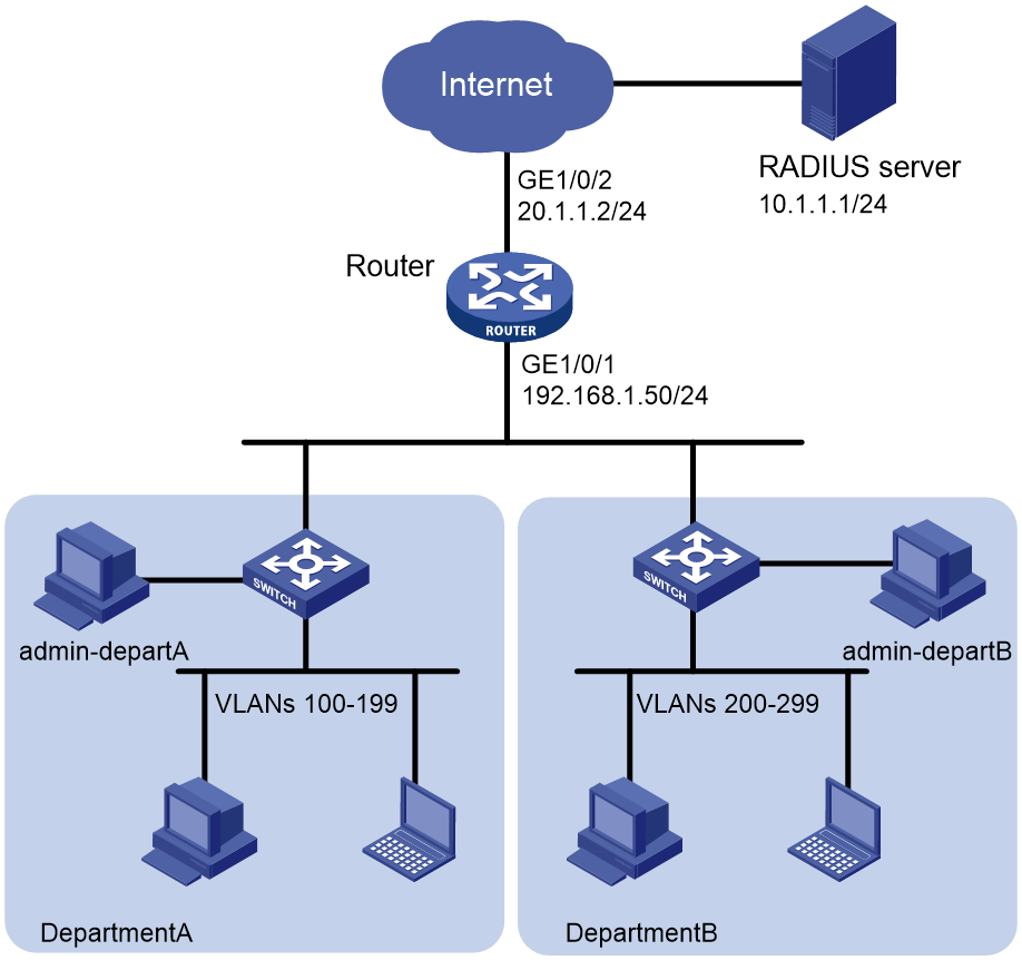
As shown in Figure 6, traffic between department A and department B is separated by allocating different VLANs to each department for internal use. To enhance network security in various department networks, use a RADIUS server to authenticate and authorize Telnet users. The specific requirements are as follows: Network administrators from department A and department B use usernames admin-departA and admin-departB, respectively, for authentication.
Network administrator admin-departA of department A has the following network management permissions:
· Configure flow control policies.
· Cannot manage interfaces or VPN resources.
· Can manage only VLANs 100 through VLAN 199.
Network administrator admin-departB of department B has the following network management permissions:
· Configure flow control policies.
· Cannot manage interfaces or VPN resources.
· Can manage only VLANs 200 through VLAN 299.
Analysis
· Create user role departA-resource and configure user role rules to allow executing QoS and ACL commands. Configure resource control policies for the users to manage only VLANs 100 through 199 and forbid users to manage interfaces or VPN resources.
· Create user role departB-resource and configure user role rules to allow executing QoS and ACL commands. Configure resource control policies for the users to manage only VLANs 200 through 299 and forbid users to manage interfaces or VPN resources.
· Configure the RADIUS server to authorize user role departA-resource for network administrators of department A, and departB-resource for network administrators of department B.
Software versions used
This configuration example was created and verified on R9141P16 of the MSR5680-X3 device.
Restrictions and guidelines
The authorization information from the RADIUS server is sent to the RADIUS client with the authentication response message. Make sure the authentication and authorization methods are the same.
Procedures
Device Configuration
1. Configure interface addresses and the routing protocol.
# Configure an IP address for interface GigabitEthernet1/0/1.
<Router> system-view
[Router] interface gigabitethernet 1/0/1
[Router-GigabitEthernet1/0/1] ip address 192.168.1.50 24
[Router-GigabitEthernet1/0/1] quit
# Configure an IP address for interface GigabitEthernet1/0/2.
[Router] interface gigabitethernet 1/0/2
[Router-GigabitEthernet1/0/2] ip address 20.1.1.2 24
[Router-GigabitEthernet1/0/2] quit
# Configure OSPF to ensure network interconnectivity.
[Router] ospf 1
[Router-ospf-1] area 0.0.0.0
[Router-ospf-1-area-0.0.0.0] network 192.168.1.0 0.0.0.255
[Router-ospf-1-area-0.0.0.0] network 20.1.1.0 0.0.0.255
[Router-ospf-1-area-0.0.0.0] quit
[Router-ospf-1] quit
2. Enable Telnet server on the device and configure the RADIUS scheme and ISP domain.
# Activate the Telnet server function on the device.
[Router] telnet server enable
# Configure Telnet user login with the AAA authentication method on VTY user lines numbered from 0 to 63.
[Router] line vty 0 63
[Router-line-vty0-63] authentication-mode scheme
[Router-line-vty0-63] quit
# Create RADIUS scheme rad.
[Router] radius scheme rad
# Configure the IP address of the primary authentication/authorization server as 10.1.1.1 and the primary accounting server as 10.1.1.1.
[Router-radius-rad] primary authentication 10.1.1.1
[Router-radius-rad] primary accounting 10.1.1.1
# Set the shared key for interaction messages with the authentication/authorization server and the primary accounting server as plaintext aabbcc.
[Router-radius-rad] key authentication simple aabbcc
[Router-radius-rad] key accounting simple aabbcc
[Router-radius-rad] quit
# Create ISP domain bbb and configure login users to use the RADIUS authentication, RADIUS authorization, and RADIUS accounting AAA methods.
[Router] domain bbb
[Router-isp-bbb] authentication login radius-scheme rad
[Router-isp-bbb] authorization login radius-scheme rad
[Router-isp-bbb] accounting login radius-scheme rad
[Router-isp-bbb] quit
3. Configure user role departA-resource on the device.
# Create user role departA-resource, configure user role rules, allow users to execute all commands related to features QoS and ACL.
[Router] role name departA-resource
[Router-role-departA-resource] rule 1 permit read write execute feature qos
[Router-role-departA-resource] rule 2 permit read write execute feature acl
# Configure the VLAN resource control policy and grant operation permission only for VLANs 100 through 199.
[Router-role-departA-resource] vlan policy deny
[Router-role-departA-resource-vlanpolicy] permit vlan 100 to 199
[Router-role-departA-resource-vlanpolicy] quit
# Configure interface and VPN resource access policies to prohibit access to all interfaces and VPN resources.
[Router-role-departA-resource] interface policy deny
[Router-role-departA-resource-ifpolicy] quit
[Router-role-departA-resource] vpn-instance policy deny
[Router-role-departA-resource-vpnpolicy] quit
[Router-role-departA-resource] quit
4. Configure user role departB-resource on device.
# Create user role departB-resource and configure the user role rules to allow executing all commands related to features QoS and ACL.
[Router] role name departB-resource
[Router-role-departB-resource] rule 1 permit read write execute feature qos
[Router-role-departB-resource] rule 2 permit read write execute feature acl
# Configure the VLAN resource control policy and grant operation permission only for VLANs 200 through 299.
[Router-role-departB-resource] vlan policy deny
[Router-role-departB-resource-vlanpolicy] permit vlan 200 to 299
[Router-role-departB-resource-vlanpolicy] quit
# Configure interface and VPN resource access policies to prohibit access to all interfaces and VPN resources.
[Router-role-departB-resource] interface policy deny
[Router-role-departB-resource-ifpolicy] quit
[Router-role-departB-resource] vpn-instance policy deny
[Router-role-departB-resource-vpnpolicy] quit
[Router-role-departB-resource] quit
[Router] quit
Configuring the RADIUS server
|
|
NOTE: This section uses iMC PLAT 7.0 (E0202) and iMC UAM 7.0 (E0202) as an example to illustrate basic configuration of the RADIUS server. |
1. Add an access device.
Log in to the IMC management platform, click the User tab, and select User Access Policy > Access Device Management > Access Device in the left navigation pane. Then, click Add.
¡ Specify the authentication and accounting port numbers to 1812 and 1813, respectively.
¡ Set the shared key for authentication and accounting for AC interaction messages as aabbcc and confirm the shared key.
¡ Select Device Management Service as the service type.
¡ Select H3C (General) as the access device type.
¡ Select or manually add the device with IP address 20.1.1.2 as an access device.
¡ Retain the default settings in the other fields and then click OK.
2. Add a device management user.
Click the User tab, and select Device User > Device User in the navigation pane. Click Add.
¡ Specify the username, set the password, and confirm the password. In this example, the username is admin-departA@bbb.
¡ Select Telnet as the service type.
¡ Add user role departA-resource.
¡ Add IP addresses of devices to be managed. In this example, the IP address range is 20.1.1.0 to 20.1.1.10.
¡ Click OK.
3. Click Add and perform the following tasks:
¡ Specify the username, set the password, and confirm the password. In this example, the username is admin-departB@bbb.
¡ Select Telnet as the service type.
¡ Add user role departB-resource.
¡ Add IP addresses of devices to be managed. In this example, the IP address range is 20.1.1.0 to 20.1.1.10.
¡ Click OK.
Verifying the configuration
1. View user role information.
Use the display role command to view information about user roles departA-resource and departB-resource.
# Display information about user role departA-resource.
<Router> display role name departA-resource
Role: departA-resource
Description:
VLAN policy: deny
Permitted VLANs: 100 to 199
Interface policy: deny
VPN instance policy: deny
Security zone policy: permit (default)
-------------------------------------------------------------------
Rule Perm Type Scope Entity
-------------------------------------------------------------------
1 permit RWX feature qos
2 permit RWX feature acl
R:Read W:Write X:Execute
# Display information about user role departB-resource.
<Router> display role name departB-resource
Role: departB-resource
Description:
VLAN policy: deny
Permitted VLANs: 200 to 299
Interface policy: deny
VPN instance policy: deny
Security zone policy: permit (default)
-------------------------------------------------------------------
Rule Perm Type Scope Entity
-------------------------------------------------------------------
1 permit RWX feature qos
2 permit RWX feature acl
R:Read W:Write X:Execute
2. Make the user log in to the device.
Use the network administrator of department A as an example.
Make the user initiate a Telnet connection to the device and enter user name admin-departA@bbb and the correct password at the prompt. Verify that you can log in to the device.
C:\Documents and Settings\user> telnet 192.168.1.50
******************************************************************************
* Copyright (c) 2004-2023 Hangzhou H3C Tech. Co., Ltd. All rights reserved. *
* Without the owner's prior written consent, *
* no decompiling or reverse-engineering shall be allowed. *
******************************************************************************
login: admin-departA@bbb
Password:
<Router>
3. Verify the user permissions.
After successfully logging in to the device as network administrator admin-departA@bbb, verify the user permissions:
¡ Verify that you can execute all commands related to QoS and ACL features. (This section creates advanced ACLs, traffic classification, traffic behavior, and QoS policies, and associates traffic classification and traffic behavior as an example.)
# Create an advanced ACL numbered 3000.
<Router> system-view
[Router] acl number 3000
# Configure the ACL rule to match all FTP data flows.
[Router-acl-ipv4-adv-3000] rule permit tcp destination-port eq ftp-data
[Router-acl-ipv4-adv-3000] quit
# Create traffic classifier 1 and specify the rule number as 3000.
[Router] traffic classifier 1
[Router-classifier-1] if-match acl 3000
[Router-classifier-1] quit
# Create traffic classifier 1 and set the rate limit value to 2000 kbps.
[Router] traffic behavior 1
[Router-behavior-1] car cir 2000
[Router-behavior-1] quit
# Create QoS policy 1, and associate traffic classifier 1 with traffic behavior 1.
[Router] qos policy 1
[Router-qospolicy-1] classifier 1 behavior 1
[Router-qospolicy-1] quit
¡ Verify that you can manage VLANs 100 through 199. (This section applies QoS policy 1 to the inbound direction of VLANs 100 through 107.)
# Apply QoS policy 1 to the inbound direction of VLAN 100 through VLAN 107 to rate limit upstream traffic for all hosts.
[Router] qos vlan-policy 1 vlan 100 to 107 inbound
¡ Verify that you cannot manage other VLANs. (This section applies QoS policy 1 to the inbound direction of VLANs 200 through 207.)
# Apply QoS policy 1 to the inbound direction of VLAN 200 through VLAN 207 to rate limit upstream traffic for all hosts.
[Router] qos vlan-policy 1 vlan 200 to 207 inbound
Permission denied.
After successfully logging in to the device as network administrator admin-departB@bbb, verify the user permissions:
¡ Verify that you can execute all commands related to QoS and ACL features. (This section creates advanced ACLs, traffic classification, traffic behavior, and QoS policies, and associates traffic classification and traffic behavior as an example.)
# Create an advanced ACL numbered 3001.
[Router] acl number 3001
# Configure the ACL rule to match all FTP data flows.
[Router-acl-ipv4-adv-3001] rule permit tcp destination-port eq ftp-data
[Router-acl-ipv4-adv-3001] quit
# Create traffic classifier 2 and specify the rule number as 3001.
[Router] traffic classifier 2
[Router-classifier-2] if-match acl 3001
[Router-classifier-2] quit
# Create traffic classifier 2 and set the rate limit value to 2000 kbps.
[Router] traffic behavior 2
[Router-behavior-2] car cir 2000
[Router-behavior-2] quit
# Create QoS policy 2, and associate traffic classifier 2 with traffic behavior 2.
[Router] qos policy 2
[Router-qospolicy-2] classifier 1 behavior 2
[Router-qospolicy-2] quit
¡ Verify that you can manage VLANs 200 through 299. (This section applies QoS policy 2 to the inbound direction of VLANs 200 through 207.)
[Router] qos vlan-policy 2 vlan 200 to 207 inbound
¡ Verify that you cannot manage other VLANs. (This section applies QoS policy 2 to the inbound direction of VLANs 100 through 107.)
[Router] qos vlan-policy 2 vlan 100 to 107 inbound
Permission denied.
Configuration files
#
telnet server enable
#
interface GigabitEthernet1/0/1
ip address 192.168.1.50 24
#
interface GigabitEthernet1/0/2
ip address 20.1.1.2 24
#
ospf 1
area 0.0.0.0
network 192.168.1.0 0.0.0.255
network 20.1.1.0 0.0.0.255
#
line vty 0 63
authentication-mode scheme
user-role network-operator
#
radius scheme rad
primary authentication 10.1.1.1
primary accounting 10.1.1.1
key authentication cipher $c$3$JzDegvL0G5KZIcJhzscTHLA4WasBVh0UOw==
key accounting cipher $c$3$CdejNYYxvjW0Y+Zydi4rZgBwjYb4h6LKmg==
#
domain bbb
authentication login radius-scheme rad
authorization login radius-scheme rad
accounting login radius-scheme rad
#
role name departA-resource
rule 1 permit read write execute feature qos
rule 2 permit read write execute feature acl
vlan policy deny
permit vlan 100 to 199
interface policy deny
vpn-instance policy deny
#
role name departB-resource
rule 1 permit read write execute feature qos
rule 2 permit read write execute feature acl
vlan policy deny
permit vlan 200 to 299
interface policy deny
vpn-instance policy deny
#
Related documentation
· Fundamentals Configuration Guide in H3C MSR5680-X3 Router Configuration Guides(V9)
· Fundamentals Command Reference in H3C MSR5680-X3 Router Command References(V9)