- Table of Contents
-
- H3C MSR5680-X3 Router Configuration Examples All-in-One-R9141-6W100
- 00-Preface
- 01-AAA Configuration Examples
- 02-ACL Configuration Examples
- 03-MPLS over ADVPN Configuration Examples
- 04-ARP Attack Protection Configuration Examples
- 05-BFD Configuration Examples
- 06-Basic BGP Configuration Examples
- 07-BGP Route Attribute-Based Route Selection Configuration Examples
- 08-EAA Monitor Policy Configuration Examples
- 09-GRE with OSPF Configuration Examples
- 10-HoVPN Configuration Examples
- 11-IGMP Configuration Examples
- 12-IPsec Configuration Examples
- 13-IPsec Digital Certificate Authentication Configuration Examples
- 14-IPv6 IS-IS Configuration Examples
- 15-IPv6 over IPv4 GRE Tunnel Configuration Examples
- 16-IPv6 over IPv4 Manual Tunnel with OSPFv3 Configuration Examples
- 17-IS-IS Configuration Examples
- 18-Combined ISATAP Tunnel and 6to4 Tunnel Configuration Examples
- 19-L2TP over IPsec Configuration Examples
- 20-Multi-Instance L2TP Configuration Examples
- 21-L2TP Multidomain Access Configuration Examples
- 22-MPLS L3VPN Configuration Examples
- 23-MPLS OAM Configuration Examples
- 24-MPLS TE Configuration Examples
- 25-Basic MPLS Configuration Examples
- 26-NAT DNS Mapping Configuration Examples
- 27-NetStream Configuration Examples
- 28-NQA Configuration Examples
- 29-NTP Configuration Examples
- 30-OSPFv3 Configuration Examples
- 31-OSPF Configuration Examples
- 32-OSPF Multi-Process Configuration Examples
- 33-OSPF Multi-Instance Configuration Examples
- 34-Portal Configuration Examples
- 35-POS Interace Configuration Examples
- 36-PPP Configuration Examples
- 37-RBAC Configuration Examples
- 38-RMON Configuration Examples
- 39-IPv4 NetStream Sampling Configuration Examples
- 40-SNMP Configuration Examples
- 41-SRv6 Configuration Examples
- 42-SSH Configuration Examples
- 43-Tcl Commands Configuration Examples
- 44-VLAN Configuration Examples
- 45-VRRP Configuration Examples
- 46-VXLAN over IPsec Configuration Examples
- 47-Cloudnet VPN Configuration Examples
- 48-Ethernet Link Aggregation Configuration Examples
- 49-Ethernet OAM Configuration Examples
- 50-Outbound Bidirectional NAT Configuration Examples
- 51-NAT Hairpin in C-S Mode Configuration Examples
- 52-Load Sharing NAT Server Configuration Examples
- 53-BIDIR-PIM Configuration Examples
- 54-Control Plane-Based QoS Policy Configuration Examples
- 55-Scheduling a Task Configuration Examples
- 56-Client-Initiated L2TP Tunnel Configuration Examples
- 57-LAC-Auto-Initiated L2TP Tunnel Configuration Examples
- 58-Authorized ARP Configuration Examples
- 59-GTS Configuration Examples
- 60-Traffic Policing Configuration Examples
- 61-Traffic Accounting Configuration Examples
- 62-PBR Configuration Examples
- 63-TFTP Client Software Upgrade Configuration Examples
- 64-FTP Client Software Upgrade Configuration Examples
- 65-FTP Server Software Upgrade Configuration Examples
- 66-Routing Policy Configuration Examples
- 67-Software Upgrade from the BootWare Menu Configuration Examples
- 68-Mirroring Configuration Examples
- Related Documents
-
| Title | Size | Download |
|---|---|---|
| 23-MPLS OAM Configuration Examples | 183.25 KB |
|
|
|
H3C Routers |
|
MPLS OAM Configuration Examples |
|
|
|
|
Copyright © 2024 New H3C Technologies Co., Ltd. All rights reserved.
No part of this manual may be reproduced or transmitted in any form or by any means without prior written consent of New H3C Technologies Co., Ltd.
Except for the trademarks of New H3C Technologies Co., Ltd., any trademarks that may be mentioned in this document are the property of their respective owners.
The information in this document is subject to change without notice.
Contents
Example: Configuring BFD for LSPs
2. Example: Configuring BFD for MPLS TE
3. Restrictions and guidelines
5. Verifying the configuration
Introduction
The following information provides MPLS OAM configuration examples.
· MPLS data plane connectivity verification.
· Data plane and control plane consistency verification.
· Fault locating.
MPLS OAM utilizes the fault management tools to detect and locate faults in LSPs, MPLS TE tunnels, and MPLS PWs, reducing the complexity of managing and maintaining MPLS networks and improving MPLS network availability.
Prerequisites
The following information applies to Comware 9-based routers. Procedures and information in the examples might be slightly different depending on the software or hardware version of the routers.
The configuration examples were created and verified in a lab environment, and all the devices were started with the factory default configuration. When you are working on a live network, make sure you understand the potential impact of every command on your network.
The following information is provided based on the assumption that you have basic knowledge of MPLS OAM.
Example: Configuring BFD for LSPs
Network configuration
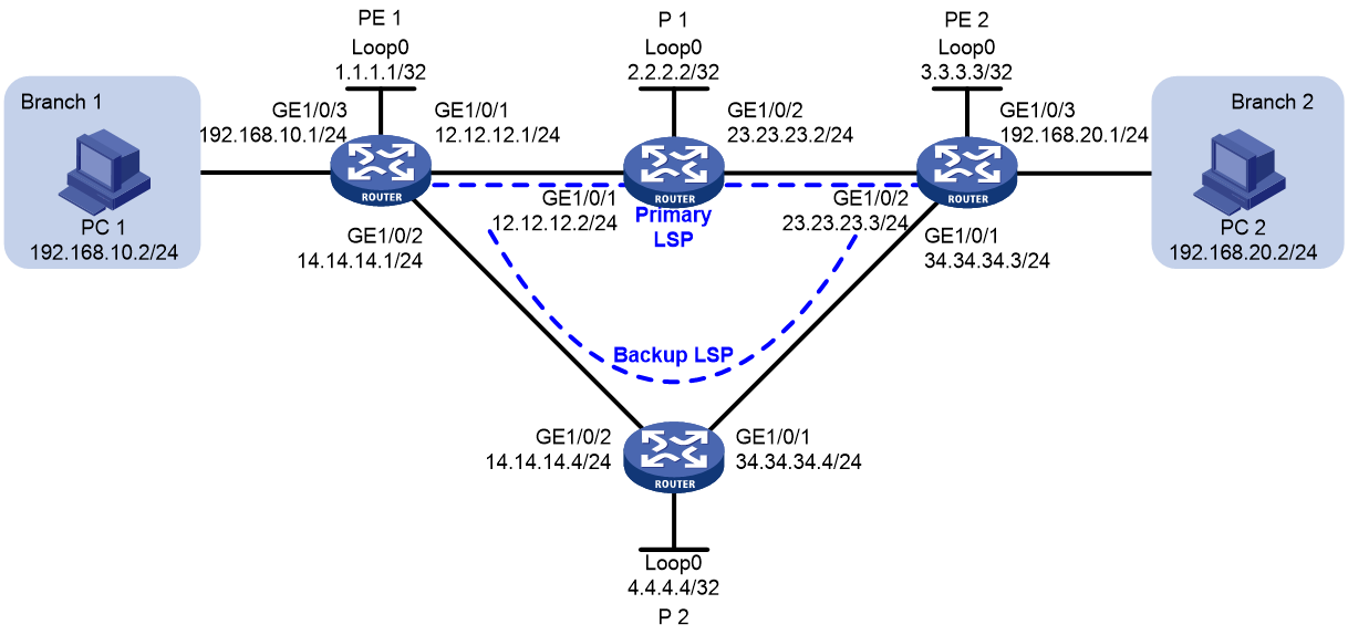
As shown in Figure 1, a company has two branches located in different places, interconnected through the MPLS backbone network of an operator. Real-time service synchronization is required between the two branches. The company requires the operator to provide HA services to ensure uninterrupted real-time business.
To meet the requirement, deploy LDP FRR in the MPLS backbone to provide two primary and backup LSP paths, and configure LDP and BFD collaboration for quick primary and backup switchover of the paths.
· Under normal conditions, use the primary path to forward traffic between PE 1 and PE 2.
· Use BFD to monitor the primary LSP. When the primary LSP fails, BFD can quickly sense and notify the LDP protocol, so traffic between PE 1 and PE 2 to quickly switch to the backup LSP for forwarding.
Software versions used
This configuration example was created and verified on R9141P16 of the MSR5680-X3 device.
Procedures
Assign IP addresses to network interfaces:
# Assign an IP address to interface GigabitEthernet 1/0/1 on PE 1.
<PE1> system-view
[PE1] interface gigabitethernet 1/0/1
[PE1-GigabitEthernet1/0/1] ip address 12.12.12.1 24
[PE1-GigabitEthernet1/0/1] quit
# Assign IP addresses to other interfaces (including loopback interfaces) as shown in Figure 1 in the same way. (Details not shown.)
Configure OSPF on each router to ensure IP connectivity between them, and enable OSPF FRR.
# Configure PE 1.
[PE1] ospf
[PE1-ospf-1] area 0
[PE1-ospf-1-area-0.0.0.0] network 1.1.1.1 0.0.0.0
[PE1-ospf-1-area-0.0.0.0] network 12.12.12.0 0.0.0.255
[PE1-ospf-1-area-0.0.0.0] network 14.14.14.0 0.0.0.255
[PE1-ospf-1-area-0.0.0.0] network 192.168.10.0 0.0.0.255
[PE1-ospf-1-area-0.0.0.0] quit
[PE1-ospf-1] fast-reroute lfa
[PE1-ospf-1] quit
# Configure P 1.
[P1] ospf
[P1-ospf-1] area 0
[P1-ospf-1-area-0.0.0.0] network 2.2.2.2 0.0.0.0
[P1-ospf-1-area-0.0.0.0] network 12.12.12.0 0.0.0.255
[P1-ospf-1-area-0.0.0.0] network 23.23.23.0 0.0.0.255
[P1-ospf-1-area-0.0.0.0] quit
[P1-ospf-1] quit
# Configure PE 2.
[PE2] ospf
[PE2-ospf-1] area 0
[PE2-ospf-1-area-0.0.0.0] network 3.3.3.3 0.0.0.0
[PE2-ospf-1-area-0.0.0.0] network 23.23.23.0 0.0.0.255
[PE2-ospf-1-area-0.0.0.0] network 34.34.34.0 0.0.0.255
[PE2-ospf-1-area-0.0.0.0] network 192.168.20.0 0.0.0.255
[PE2-ospf-1-area-0.0.0.0] quit
[PE2-ospf-1] fast-reroute lfa
[PE2-ospf-1] quit
# Configure P 2.
[P2] ospf
[P2-ospf-1] area 0
[P2-ospf-1-area-0.0.0.0] network 4.4.4.4 0.0.0.0
[P2-ospf-1-area-0.0.0.0] network 14.14.14.0 0.0.0.255
[P2-ospf-1-area-0.0.0.0] network 34.34.34.0 0.0.0.255
[P2-ospf-1-area-0.0.0.0] quit
[P2-ospf-1] quit
# Adjust the OSPF cost values of GigabitEthernet 1/0/1 and GigabitEthernet 1/0/2 on P 2 to ensure the backup LSP has a bigger OSPF cost than the primary LSP.
[P2] interface gigabitethernet 1/0/1
[P2-GigabitEthernet1/0/1] ospf cost 10
[P2-GigabitEthernet1/0/1] quit
[P2] interface gigabitethernet 1/0/2
[P2-GigabitEthernet1/0/2] ospf cost 10
[P2-GigabitEthernet1/0/2] quit
Configure MPLS basic capability and enable LDP:
# Configure PE 1.
[PE1] mpls lsr-id 1.1.1.1
[PE1] mpls ldp
[PE1-ldp] quit
[PE1] interface gigabitethernet 1/0/1
[PE1-GigabitEthernet1/0/1] mpls enable
[PE1-GigabitEthernet1/0/1] mpls ldp enable
[PE1-GigabitEthernet1/0/1] quit
[PE1] interface gigabitethernet 1/0/2
[PE1-GigabitEthernet1/0/2] mpls enable
[PE1-GigabitEthernet1/0/2] mpls ldp enable
[PE1-GigabitEthernet1/0/2] quit
# Configure P 1.
[P1] mpls lsr-id 2.2.2.2
[P1] mpls ldp
[P1-ldp] quit
[P1] interface gigabitethernet 1/0/1
[P1-GigabitEthernet1/0/1] mpls enable
[P1-GigabitEthernet1/0/1] mpls ldp enable
[P1-GigabitEthernet1/0/1] quit
[P1] interface gigabitethernet 1/0/2
[P1-GigabitEthernet1/0/2] mpls enable
[P1-GigabitEthernet1/0/2] mpls ldp enable
[P1-GigabitEthernet1/0/2] quit
# Configure PE 2.
[PE2] mpls lsr-id 3.3.3.3
[PE2] mpls ldp
[PE2-ldp] quit
[PE2] interface gigabitethernet 1/0/1
[PE2-GigabitEthernet1/0/1] mpls enable
[PE2-GigabitEthernet1/0/1] mpls ldp enable
[PE2-GigabitEthernet1/0/1] quit
[PE2] interface gigabitethernet 1/0/2
[PE2-GigabitEthernet1/0/2] mpls enable
[PE2-GigabitEthernet1/0/2] mpls ldp enable
[PE2-GigabitEthernet1/0/2] quit
# Configure P 2.
[P2] mpls lsr-id 4.4.4.4
[P2] mpls ldp
[P2-ldp] quit
[P2] interface gigabitethernet 1/0/1
[P2-GigabitEthernet1/0/1] mpls enable
[P2-GigabitEthernet1/0/1] mpls ldp enable
[P2-GigabitEthernet1/0/1] quit
[P2] interface gigabitethernet 1/0/2
[P2-GigabitEthernet1/0/2] mpls enable
[P2-GigabitEthernet1/0/2] mpls ldp enable
[P2-GigabitEthernet1/0/2] quit
After the configuration is completed, verify that an LDP session in operational state has been established on each router. Take PE 1 as an example:
[PE1] display mpls ldp peer
Total number of peers: 2
Peer LDP ID State Role GR MD5 KA Sent/Rcvd
2.2.2.2:0 Operational Passive Off Off 55/55
4.4.4.4:0 Operational Passive Off Off 6/6
# On PE 1, configure IP prefix list PE1, and configure LDP to use only the routes permitted by the prefix list to establish LSPs.
[PE1] ip prefix-list PE1 index 10 permit 192.168.10.0 24
[PE1] ip prefix-list PE1 index 20 permit 192.168.20.0 24
[PE1] ip prefix-list PE1 index 30 permit 1.1.1.1 32
[PE1] ip prefix-list PE1 index 40 permit 3.3.3.3 32
[PE1] mpls ldp
[PE1-ldp] lsp-trigger prefix-list PE1
[PE1-ldp] quit
# On P 1, configure IP prefix list P1, and configure LDP to use only the routes permitted by the prefix list to establish LSPs.
[P1] ip prefix-list P1 index 10 permit 192.168.10.0 24
[P1] ip prefix-list P1 index 20 permit 192.168.20.0 24
[P1] ip prefix-list P1 index 30 permit 1.1.1.1 32
[P1] ip prefix-list P1 index 40 permit 3.3.3.3 32
[P1] mpls ldp
[P1-ldp] lsp-trigger prefix-list P1
[P1-ldp] quit
# On PE 2, configure IP prefix list PE 2, and configure LDP to use only the routes permitted by the prefix list to establish LSPs.
[PE2] ip prefix-list PE2 index 10 permit 192.168.10.0 24
[PE2] ip prefix-list PE2 index 20 permit 192.168.20.0 24
[PE2] ip prefix-list PE2 index 30 permit 1.1.1.1 32
[PE2] ip prefix-list PE2 index 40 permit 3.3.3.3 32
[PE2] mpls ldp
[PE2-ldp] lsp-trigger prefix-list PE2
[PE2-ldp] quit
# On P 2, configure IP prefix list P2, and configure LDP to use only the routes permitted by the prefix list to establish LSPs.
[P2] ip prefix-list P2 index 10 permit 192.168.10.0 24
[P2] ip prefix-list P2 index 20 permit 192.168.20.0 24
[P2] ip prefix-list P2 index 30 permit 1.1.1.1 32
[P2] ip prefix-list P2 index 40 permit 3.3.3.3 32
[P2] mpls ldp
[P2-ldp] lsp-trigger prefix-list P2
[P2-ldp] quit
# After the configuration is completed, execute the display mpls ldp lsp command on PE 1 to view LDP LSP information. The output shows that the LSP destined for subnet 192.168.20.0/24 has been established.
[PE1] display mpls ldp lsp
Status Flags: * - stale, L - liberal, B - backup
FECs: 4 Ingress: 4 Transit: 4 Egress: 2
FEC In/Out Label Nexthop OutInterface
1.1.1.1/32 3/-
-/1151(L)
-/1149(L)
3.3.3.3/32 -/1150 12.12.12.2 GE1/0/1
1150/1150 12.12.12.2 GE1/0/1
-/1150(B) 14.14.14.4 GE1/0/2
1150/1150(B) 14.14.14.4 GE1/0/2
192.168.10.0/24 1148/-
-/1148(L)
-/1148(L)
192.168.20.0/24 -/1147 12.12.12.2 GE1/0/1
1147/1147 12.12.12.2 GE1/0/1
-/1147(B) 14.14.14.4 GE1/0/2
1147/1147(B) 14.14.14.4 GE1/0/2
# Enable BFD for MPLS and configure BFD to detect the LSP connectivity.
[PE1] mpls bfd 3.3.3.3 32
[PE2] mpls bfd 1.1.1.1 32
Verifying the configuration
1. After the configuration is completed, execute the display mpls bfd command on PE 1 and PE 2 to verify the BFD sessions established for LSPs. Use PE1 as an example.
[PE1] display mpls bfd
Total number of sessions: 2, 2 up, 0 down, 0 init
FEC Type: LSP
FEC Info:
Destination: 1.1.1.1
Mask Length: 32
NHLFE ID: -
Local Discr: 514 Remote Discr: 513
Source IP: 1.1.1.1 Destination IP: 3.3.3.3
Session State: Up Session Role: Active
Template Name: -
FEC Type: LSP
FEC Info:
Destination: 3.3.3.3
Mask Length: 32
NHLFE ID: 1028
Local Discr: 513 Remote Discr: 514
Source IP: 1.1.1.1 Destination IP: 127.0.0.1
Session State: Up Session Role: Passive
Template Name: -
Use the tracert mpls ipv4 command on PE 1 to verify that the primary LSP is currently used. (Before you use tracert on a device, you must enable sending of ICMP timeout packets on the intermediate devices and sending of ICMP destination unreachable packets on the destination device.)
<PE1> tracert mpls -a 192.168.10.1 ipv4 192.168.20.0 24
MPLS trace route FEC 192.168.20.0/24
TTL Replier Time Type Downstream
0 Ingress 12.12.12.2/[1141]
1 12.12.12.2 2 ms Transit 23.23.23.3/[1141]
2 23.23.23.3 2 ms Egress
Ping PE 2 from PE 1 continuously, during which shut down interface GigabitEthernet 1/0/1 on P 1. Check whether the communication is interrupted:
# Ping PE 2 from PE 1 continuously.
<PE1> ping -c 100000 -a 192.168.10.1 192.168.20.1
Ping 192.168.20.1 (192.168.20.1) from 192.168.10.1: 56 data bytes, press CTRL_C
to break
56 bytes from 192.168.20.1: icmp_seq=0 ttl=254 time=2.576 ms
56 bytes from 192.168.20.1: icmp_seq=1 ttl=254 time=1.996 ms
...
# Shut down interface GigabitEthernet 1/0/1 on P 1.
[P1] interface gigabitethernet1/0/1
[P1-GigabitEthernet1/0/1] shutdown
# On PE 1, view the output of the ping command. The output shows that the communication was interrupted and then resumed quickly.
<PE1> ping -c 100000 -a 192.168.10.1 192.168.20.1
Ping 192.168.20.1 (192.168.20.1) from 192.168.10.1: 56 data bytes, press CTRL_C
to break
56 bytes from 192.168.20.1: icmp_seq=0 ttl=254 time=2.576 ms
56 bytes from 192.168.20.1: icmp_seq=1 ttl=254 time=1.996 ms
...
56 bytes from 192.168.20.1: icmp_seq=7 ttl=254 time=2.214 ms
Request time out
56 bytes from 192.168.20.1: icmp_seq=9 ttl=254 time=2.659 ms
56 bytes from 192.168.20.1: icmp_seq=10 ttl=254 time=5.049 ms
56 bytes from 192.168.20.1: icmp_seq=11 ttl=254 time=2.098 ms
56 bytes from 192.168.20.1: icmp_seq=12 ttl=254 time=2.225 ms
56 bytes from 192.168.20.1: icmp_seq=13 ttl=254 time=2.187 ms
--- Ping statistics for 192.168.20.1 ---
14 packet(s) transmitted, 13 packet(s) received, 7.1% packet loss
round-trip min/avg/max/std-dev = 1.990/2.455/5.049/0.772 ms
Check whether link switchover has occurred:
# Execute the tracert mpls ipv4 command on PE 1. The output shows that the backup LSP is currently used.
<PE1> tracert mpls -a 192.168.10.1 ipv4 192.168.20.0 24
MPLS trace route FEC 192.168.20.0/24
TTL Replier Time Type Downstream
0 Ingress 14.14.14.4/[1133]
1 14.14.14.4 2 ms Transit 34.34.34.3/[1141]
2 34.34.34.3 2 ms Egress
2. Configuration files
· PE 1
#
ospf 1
fast-reroute lfa
area 0.0.0.0
network 1.1.1.1 0.0.0.0
network 12.12.12.0 0.0.0.255
network 14.14.14.0 0.0.0.255
network 192.168.10.0 0.0.0.255
#
mpls lsr-id 1.1.1.1
#
mpls ldp
lsp-trigger prefix-list PE1
#
mpls bfd enable
#
interface LoopBack0
ip address 1.1.1.1 255,255,255,255
#
interface GigabitEthernet1/0/1
port link-mode route
ip address 12.12.12.1 255.255.255.0
mpls enable
mpls ldp enable
#
interface GigabitEthernet1/0/2
port link-mode route
ip address 14.14.14.1 255.255.255.0
mpls enable
mpls ldp enable
#
interface GigabitEthernet1/0/3
port link-mode route
ip address 192.168.10.1 255.255.255.0
#
ip prefix-list PE1 index 10 permit 192.168.10.0 24
ip prefix-list PE1 index 20 permit 192.168.20.0 24
ip prefix-list PE1 index 30 permit 1.1.1.1 32
ip prefix-list PE1 index 40 permit 3.3.3.3 32
#
mpls bfd 3.3.3.3 32
#
· PE 2
#
ospf 1
fast-reroute lfa
area 0.0.0.0
network 3.3.3.3 0.0.0.0
network 23.23.23.0 0.0.0.255
network 34.34.34.0 0.0.0.255
network 192.168.20.0 0.0.0.255
#
mpls lsr-id 3.3.3.3
#
mpls ldp
lsp-trigger prefix-list PE2
#
mpls bfd enable
#
interface LoopBack0
ip address 3.3.3.3 255,255,255,255
#
interface GigabitEthernet1/0/1
port link-mode route
ip address 34.34.34.3 255.255.255.0
mpls enable
mpls ldp enable
#
interface GigabitEthernet1/0/2
port link-mode route
ip address 23.23.23.3 255.255.255.0
mpls enable
mpls ldp enable
#
interface GigabitEthernet1/0/3
port link-mode route
ip address 192.168.20.1 255.255.255.0
#
ip prefix-list PE2 index 10 permit 192.168.10.0 24
ip prefix-list PE2 index 20 permit 192.168.20.0 24
ip prefix-list PE2 index 30 permit 1.1.1.1 32
ip prefix-list PE2 index 40 permit 3.3.3.3 32
#
mpls bfd 1.1.1.1 32
#
· P 1
#
ospf 1
area 0.0.0.0
network 2.2.2.2 0.0.0.0
network 12.12.12.0 0.0.0.255
network 23.23.23.0 0.0.0.255
#
mpls lsr-id 2.2.2.2
#
mpls ldp
lsp-trigger prefix-list P1
#
interface LoopBack0
ip address 2.2.2.2 255,255,255,255
#
interface GigabitEthernet1/0/1
port link-mode route
ip address 12.12.12.2 255.255.255.0
mpls enable
mpls ldp enable
#
interface GigabitEthernet1/0/2
port link-mode route
ip address 23.23.23.2 255.255.255.0
mpls enable
mpls ldp enable
#
ip prefix-list P1 index 10 permit 192.168.10.0 24
ip prefix-list P1 index 20 permit 192.168.20.0 24
ip prefix-list P1 index 30 permit 1.1.1.1 32
ip prefix-list P1 index 40 permit 3.3.3.3 32
#
· P 2
#
ospf 1
area 0.0.0.0
network 4.4.4.4 0.0.0.0
network 14.14.14.0 0.0.0.255
network 34.34.34.0 0.0.0.255
#
mpls lsr-id 4.4.4.4
#
mpls ldp
lsp-trigger prefix-list P2
#
interface LoopBack0
ip address 4.4.4.4 255,255,255,255
#
interface GigabitEthernet1/0/1
port link-mode route
ip address 34.34.34.4 255.255.255.0
ospf cost 10
mpls enable
mpls ldp enable
#
interface GigabitEthernet1/0/2
port link-mode route
ip address 14.14.14.4 255.255.255.0
ospf cost 10
mpls enable
mpls ldp enable
#
ip prefix-list P2 index 10 permit 192.168.10.0 24
ip prefix-list P2 index 20 permit 192.168.20.0 24
ip prefix-list P2 index 30 permit 1.1.1.1 32
ip prefix-list P2 index 40 permit 3.3.3.3 32
#
2. Example: Configuring BFD for MPLS TE
1. Network configuration
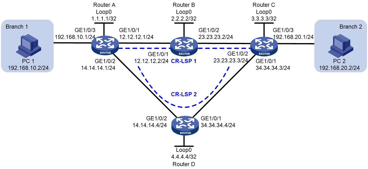
As shown in Figure 2, a company has two branches located in different places, interconnected through the MPLS TE tunnel over the network of the operator. Real-time service synchronization is required MPLS two branches. The company requires the operator to provide HA services to ensure uninterrupted real-time business.
To meet the requirement, deploy a primary and a backup CRLSP for the MPLS TE tunnel, and configure BFD for the MPLS TE tunnel for quick primary and backup switchover of the CRLSPs.
· Under normal conditions, use the primary CRLSP (CRLSP 1) to forward traffic between Router A and Router C.
· Use BFD to monitor the primary CRLSP. When the primary CRLSP fails, BFD can quickly sense and notify the RSVP protocol, so traffic between Router A and Router C to quickly switch to the backup CRLSP for forwarding.
2. Software versions used
This configuration example was created and verified on R9141P16 of the MSR5680-X3 device
3. Restrictions and guidelines
4. Procedures
1. Assign IP addresses to network interfaces:
# Assign an IP address to interface GigabitEthernet 1/0/1 on Router A.
<RouterA> system-view
[RouterA] interface gigabitethernet 1/0/1
[RouterA-GigabitEthernet1/0/1] ip address 12.12.12.1 24
[RouterA-GigabitEthernet1/0/1] quit
# Assign IP addresses to other interfaces (including loopback interfaces) as shown in Figure 2 in the same way. (Details not shown.)
2. Configure the LSR ID, enable MPLS, MPLS TE, and RSVP-TE on each router:
[RouterA] mpls te
[RouterA-te] quit
[RouterA] rsvp
[RouterA-rsvp] quit
[RouterA] interface gigabitethernet 1/0/1
[RouterA-GigabitEthernet1/0/1] mpls enable
[RouterA-GigabitEthernet1/0/1] mpls te enable
[RouterA-GigabitEthernet1/0/1] rsvp enable
[RouterA-GigabitEthernet1/0/1] quit
[RouterA] interface gigabitethernet 1/0/2
[RouterA-GigabitEthernet1/0/2] mpls enable
[RouterA-GigabitEthernet1/0/2] mpls te enable
[RouterA-GigabitEthernet1/0/2] rsvp enable
[RouterA-GigabitEthernet1/0/2] quit
3. Configure OSPF on each router to ensure IP connectivity between them, enable opaque LSA advertisement and reception for OSPF, and enable MPLS TE in OSPF area 0.
# Configure Router A.
[RouterA] ospf
[RouterA-ospf-1] opaque-capability enable
[RouterA-ospf-1] area 0
[RouterA-ospf-1-area-0.0.0.0] mpls te enable
[RouterA-ospf-1-area-0.0.0.0] network 1.1.1.1 0.0.0.0
[RouterA-ospf-1-area-0.0.0.0] network 12.12.12.0 0.0.0.255
[RouterA-ospf-1-area-0.0.0.0] network 14.14.14.0 0.0.0.255
[RouterA-ospf-1-area-0.0.0.0] network 192.168.10.0 0.0.0.255
[RouterA-ospf-1-area-0.0.0.0] quit
[RouterA-ospf-1] quit
# Configure Router B.
[RouterB] ospf
[RouterB-ospf-1] opaque-capability enable
[RouterB-ospf-1] area 0
[RouterB-ospf-1-area-0.0.0.0] mpls te enable
[RouterB-ospf-1-area-0.0.0.0] network 2.2.2.2 0.0.0.0
[RouterB-ospf-1-area-0.0.0.0] network 12.12.12.0 0.0.0.255
[RouterB-ospf-1-area-0.0.0.0] network 23.23.23.0 0.0.0.255
[RouterB-ospf-1-area-0.0.0.0] quit
[RouterB-ospf-1] quit
# Configure Router C.
[RouterC] ospf
[RouterC-ospf-1] opaque-capability enable
[RouterC ospf-1] area 0
[RouterC-ospf-1-area-0.0.0.0] mpls te enable
[RouterC-ospf-1-area-0.0.0.0] network 3.3.3.3 0.0.0.0
[RouterC ospf-1-area-0.0.0.0] network 23.23.23.0 0.0.0.255
[RouterC ospf-1-area-0.0.0.0] network 34.34.34..0 0.0.0.255
[RouterC ospf-1-area-0.0.0.0] network 192.168.20.0 0.0.0.255
[RouterC ospf-1-area-0.0.0.0] quit
[RouterC ospf-1] quit
Configure Router D.
[RouterD] ospf
[RouterD-ospf-1] opaque-capability enable
[RouterD-ospf-1] area 0
[RouterC-ospf-1-area-0.0.0.0] mpls te enable
[RouterD-ospf-1-area-0.0.0.0] network 4.4.4.4 0.0.0.0
[RouterD-ospf-1-area-0.0.0.0] network 14.14.14.0 0.0.0.255
[RouterD-ospf-1-area-0.0.0.0] network 34.34.34.0 0.0.0.255
[RouterD-ospf-1-area-0.0.0.0] quit
[RouterD-ospf-1] quit
[RouterA] interface tunnel 3 mode mpls-te
[RouterA-Tunnel3] ip address 9.1.1.1 255.255.255.0
[RouterA-Tunnel3] destination 3.3.3.3
[RouterA-Tunnel3] mpls te signaling rsvp-te
[RouterA-Tunnel3] mpls te backup hot-standby
[RouterA-Tunnel3] quit
# Configure explicit paths cr-lsp1 and cr-lsp2 for the tunnel. Set the preference of path cr-lsp1 to 1 and that of path cr-lsp2 to 2, so the tunnel uses CRLSP 1 as the primary CRLSP and CRLSP 2 as the backup CRLSP.
[RouterA] explicit-path cr-lsp1
[RouterA-explicit-path-cr-lsp1] nexthop 12.12.12.2
[RouterA-explicit-path-cr-lsp1] quit
[RouterA] explicit-path cr-lsp2
[RouterA-explicit-path-cr-lsp2] nexthop 14.14.14.4
[RouterA-explicit-path-cr-lsp2] quit
[RouterA] interface tunnel 3
[RouterA-Tunnel3] mpls te path preference 1 explicit-path cr-lsp1
[RouterA-Tunnel3] mpls te path preference 2 explicit-path cr-lsp2
[RouterA-Tunnel3] quit
[RouterC] interface tunnel 3 mode mpls-te
[RouterC-Tunnel3] ip address 9.3.3.3 255.255.255.0
[RouterC-Tunnel3] destination 1.1.1.1
[RouterC-Tunnel3] mpls te signaling rsvp-te
[RouterC-Tunnel3] mpls te backup hot-standby
[RouterC-Tunnel3] quit
# Configure explicit paths cr-lsp1 and cr-lsp2 for the tunnel. Set the preference of path cr-lsp1 to 1 and that of path cr-lsp2 to 2, so the tunnel uses CRLSP 1 as the primary CRLSP and CRLSP 2 as the backup CRLSP.
[RouterC] explicit-path cr-lsp1
[RouterC-explicit-path-cr-lsp1] nexthop 23.23.23.2
[RouterC-explicit-path-cr-lsp1] quit
[RouterC] explicit-path cr-lsp2
[RouterC-explicit-path-cr-lsp2] nexthop 34.34.34.4
[RouterC-explicit-path-cr-lsp2] quit
[RouterC] interface tunnel 3
[RouterC-Tunnel3] mpls te path preference 1 explicit-path cr-lsp1
[RouterC-Tunnel3] mpls te path preference 2 explicit-path cr-lsp2
[RouterC-Tunnel3] quit
5. Configure a static route to direct traffic to the MPLS TE tunnel:
[RouterA] ip route-static 192.168.20.0 24 tunnel 3 preference 1
# Configure a static route on Router C to direct the traffic destined for 192.168.10.0/24 to MPLS TE tunnel interface Tunnel 3.
[RouterC] ip route-static 192.168.10.0 24 tunnel 3 preference 1
6. Enable BFD for MPLS and configure BFD to detect the TE tunnel connectivity.
# Configure Router A.
[RouterA] mpls bfd enable
[RouterA] interface tunnel 3
[RouterA-Tunnel3] mpls bfd
[RouterA-Tunnel3] quit
# Configure Router C.
[RouterC] mpls bfd enable
[RouterC] interface tunnel 3
[RouterC-Tunnel3] mpls bfd
[RouterC-Tunnel3] quit
5. Verifying the configuration
# Execute the display interface tunnel command on Router A and Router C. The output shows that Tunnel 3 has come up. Take Router A as an example:
<RouterA> display interface tunnel
Tunnel3
Current state: Up
Line protocol state: Up
Description: Tunnel3 Interface
Bandwidth: 64kbps
Maximum Transmit Unit: 1496
Internet Address is 9.1.1.1/24 Primary
Tunnel source unknown, destination 3.3.3.3
Tunnel TTL 255
Tunnel protocol/transport CR_LSP
Last clearing of counters: Never
Last 300 seconds input rate: 0 bytes/sec, 0 bits/sec, 0 packets/sec
Last 300 seconds output rate: 0 bytes/sec, 0 bits/sec, 0 packets/sec
Input: 0 packets, 0 bytes, 0 drops
Output: 0 packets, 0 bytes, 0 drops
2. Execute the tracert mpls te command on Router A to verify that CRLSP 1 is currently used. (Before you use tracert on a device, you must enable sending of ICMP timeout packets on the intermediate devices and sending of ICMP destination unreachable packets on the destination device.)
<RouterA> tracert mpls te Tunnel 3
MPLS trace route TE tunnel Tunnel3
TTL Replier Time Type Downstream
0 Ingress 12.12.12.2/[1140]
1 12.12.12.2 30 ms Transit 23.23.23.3/[3]
2 23.23.23.3 2 ms Egress
3. Use the display mpls bfd command to view information about the BFD sessions for the primary CRLSP and backup CRLSP of the MPLS TE tunnel. Take Router A as an example:
<RouterA> display mpls bfd te tunnel 3
Total number of sessions: 2, 2 up, 0 down, 0 init
FEC Type: TE Tunnel
FEC Info:
Send Addr: 1.1.1.1
End Addr: 3.3.3.3
Tunnel ID: 3
LSP ID : 6681
NHLFE ID: 1037
Local Discr: 513 Remote Discr: 513
Source IP: 1.1.1.1 Destination IP: 127.0.0.1
Session State: Up Session Role: Passive
Template Name: -
FEC Type: TE Tunnel
FEC Info:
Send Addr: 1.1.1.1
End Addr: 3.3.3.3
Tunnel ID: 3
LSP ID : 6682
NHLFE ID: 1039
Local Discr: 514 Remote Discr: 514
Source IP: 1.1.1.1 Destination IP: 127.0.0.2
Session State: Up Session Role: Passive
Template Name: -
4. Ping Router C from Router A continuously, during which shut down interface GigabitEthernet 1/0/1 on Router B. Check whether the communication is interrupted:
Ping Router C from Router A continuously.
<RouterA> ping -c 10000 -a 192.168.10.1 192.168.20.1
Ping 192.168.20.1 (192.168.20.1) from 192.168.10.1: 56 data bytes, press CTRL_C
to break
56 bytes from 192.168.20.1: icmp_seq=0 ttl=254 time=3.443 ms
56 bytes from 192.168.20.1: icmp_seq=1 ttl=254 time=2.835 ms
...
# Shut down interface GigabitEthernet 1/0/1 on Router B.
[RouterB] interface gigabitethernet1/0/1
[RouterB-GigabitEthernet1/0/1] shutdown
# On Router A, view the output of the ping command. The output shows that the communication was interrupted and then resumed quickly.
<RouterA> ping -c 10000 -a 192.168.10.1 192.168.20.1
Ping 192.168.20.1 (192.168.20.1) from 192.168.10.1: 56 data bytes, press CTRL_C
to break
56 bytes from 192.168.20.1: icmp_seq=0 ttl=254 time=3.443 ms
56 bytes from 192.168.20.1: icmp_seq=1 ttl=254 time=2.835 ms
...
56 bytes from 192.168.20.1: icmp_seq=22 ttl=254 time=3.503 ms
Request time out
56 bytes from 192.168.20.1: icmp_seq=24 ttl=254 time=2.434 ms
56 bytes from 192.168.20.1: icmp_seq=25 ttl=254 time=3.196 ms
56 bytes from 192.168.20.1: icmp_seq=26 ttl=254 time=3.592 ms
56 bytes from 192.168.20.1: icmp_seq=27 ttl=254 time=2.305 ms
56 bytes from 192.168.20.1: icmp_seq=28 ttl=254 time=2.139 ms
--- Ping statistics for 192.168.20.1 ---
29 packet(s) transmitted, 28 packet(s) received, 3.4% packet loss
round-trip min/avg/max/std-dev = 2.076/2.701/3.921/0.609 ms
5. Check whether link switchover has occurred:
# Execute the tracert mpls te command on Router A to verify that CRLSP 2 is currently used.
<RouterA> tracert mpls te Tunnel 3
MPLS trace route TE tunnel Tunnel3
TTL Replier Time Type Downstream
0 Ingress 14.14.14.4/[1142]
1 14.14.14.4 198 ms Transit 34.34.34.3/[3]
2 34.34.34.3 7 ms Egress
# Execute the display mpls bfd command. You can see the BFD session for CRLSP 2 of the MPLS TE tunnel. Take Router A as an example:
<RouterA> display mpls bfd te tunnel 3
Total number of sessions: 1, 1 up, 0 down, 0 init
FEC Type: TE Tunnel
FEC Info:
Send Addr: 1.1.1.1
End Addr: 3.3.3.3
Tunnel ID: 3
LSP ID : 6682
NHLFE ID: 1039
Local Discr: 514 Remote Discr: 514
Source IP: 1.1.1.1 Destination IP: 127.0.0.2
Session State: Up Session Role: Passive
Template Name: -
6. Configuration files
· Router A:
#
ospf 1
area 0.0.0.0
network 1.1.1.1 0.0.0.0
network 12.12.12.0 0.0.0.255
network 14.14.14.0 0.0.0.255
network 192.168.10.0 0.0.0.255
mpls te enable
#
mpls lsr-id 1.1.1.1
#
mpls te
#
explicit-path cr-lsp1
nexthop index 1 12.12.12.2 include strict
#
explicit-path cr-lsp2
nexthop index 1 14.14.14.4 include strict
#
rsvp
#
mpls bfd enable
#
interface LoopBack0
ip address 1.1.1.1 255,255,255,255
#
interface GigabitEthernet1/0/1
port link-mode route
ip address 12.12.12.1 255.255.255.0
mpls enable
mpls te enable
rsvp enable
#
interface GigabitEthernet1/0/2
port link-mode route
ip address 14.14.14.1 255.255.255.0
mpls enable
mpls te enable
rsvp enable
#
interface GigabitEthernet1/0/3
port link-mode route
ip address 192.168.10.1 255.255.255.0
#
interface Tunnel3 mode mpls-te
ip address 9.1.1.1 255.255.255.0
mpls te path preference 1 explicit-path cr-lsp1
mpls te path preference 2 explicit-path cr-lsp2
mpls te backup hot-standby
mpls bfd
destination 3.3.3.3
#
ip route-static 192.168.20.0 24 Tunnel3 preference 1
#
#
ospf 1
area 0.0.0.0
network 2.2.2.2 0.0.0.0
network 12.12.12.0 0.0.0.255
network 23.23.23.0 0.0.0.255
mpls te enable
#
mpls lsr-id 2.2.2.2
#
mpls te
#
rsvp
#
interface LoopBack0
ip address 2.2.2.2 255,255,255,255
#
interface GigabitEthernet1/0/1
port link-mode route
ip address 12.12.12.2 255.255.255.0
mpls enable
mpls te enable
rsvp enable
#
interface GigabitEthernet1/0/2
port link-mode route
ip address 23.23.23.2 255.255.255.0
mpls enable
mpls te enable
rsvp enable
#
· Router C:
#
ospf 1
area 0.0.0.0
network 3.3.3.3 0.0.0.0
network 23.23.23.0 0.0.0.255
network 34.34.34.0 0.0.0.255
network 192.168.20.0 0.0.0.255
mpls te enable
#
mpls lsr-id 3.3.3.3
#
mpls te
#
explicit-path cr-lsp1
nexthop index 1 23.23.23.2 include strict
#
explicit-path cr-lsp2
nexthop index 1 34.34.34.4 include strict
#
rsvp
#
mpls bfd enable
#
interface LoopBack0
ip address 3.3.3.3 255,255,255,255
#
interface GigabitEthernet1/0/1
port link-mode route
ip address 34.34.34.3 255.255.255.0
mpls enable
mpls te enable
rsvp enable
#
interface GigabitEthernet1/0/2
port link-mode route
ip address 23.23.23.3 255.255.255.0
mpls enable
mpls te enable
rsvp enable
#
interface GigabitEthernet1/0/3
port link-mode route
ip address 192.168.20.1 255.255.255.0
#
interface Tunnel3 mode mpls-te
ip address 9.3.3.3 255.255.255.0
mpls te path preference 1 explicit-path cr-lsp1
mpls te path preference 2 explicit-path cr-lsp2
mpls te backup hot-standby
mpls bfd
destination 1.1.1.1
#
ip route-static 192.168.10.0 24 Tunnel3 preference 1
#
· Router D:
#
ospf 1
area 0.0.0.0
network 4.4.4.4 0.0.0.0
network 14.14.14.0 0.0.0.255
network 34.34.34.0 0.0.0.255
mpls te enable
#
mpls lsr-id 4.4.4.4
#
mpls te
#
rsvp
#
interface LoopBack0
ip address 4.4.4.4 255,255,255,255
#
interface GigabitEthernet1/0/1
port link-mode route
ip address 34.34.34.4 255.255.255.0
mpls enable
mpls te enable
rsvp enable
#
interface GigabitEthernet1/0/2
port link-mode route
ip address 14.14.14.4 255.255.255.0
mpls enable
mpls te enable
rsvp enable
#
3. Related documentation
· MPLS Configuration Guide in H3C MSR5680-X3 Router Configuration Guides (V9)
· MPLS Command Reference in H3C MSR5680-X3 Router Command References (V9)