- Table of Contents
-
- H3C MSR5680-X3 Router Configuration Examples All-in-One-R9141-6W100
- 00-Preface
- 01-AAA Configuration Examples
- 02-ACL Configuration Examples
- 03-MPLS over ADVPN Configuration Examples
- 04-ARP Attack Protection Configuration Examples
- 05-BFD Configuration Examples
- 06-Basic BGP Configuration Examples
- 07-BGP Route Attribute-Based Route Selection Configuration Examples
- 08-EAA Monitor Policy Configuration Examples
- 09-GRE with OSPF Configuration Examples
- 10-HoVPN Configuration Examples
- 11-IGMP Configuration Examples
- 12-IPsec Configuration Examples
- 13-IPsec Digital Certificate Authentication Configuration Examples
- 14-IPv6 IS-IS Configuration Examples
- 15-IPv6 over IPv4 GRE Tunnel Configuration Examples
- 16-IPv6 over IPv4 Manual Tunnel with OSPFv3 Configuration Examples
- 17-IS-IS Configuration Examples
- 18-Combined ISATAP Tunnel and 6to4 Tunnel Configuration Examples
- 19-L2TP over IPsec Configuration Examples
- 20-Multi-Instance L2TP Configuration Examples
- 21-L2TP Multidomain Access Configuration Examples
- 22-MPLS L3VPN Configuration Examples
- 23-MPLS OAM Configuration Examples
- 24-MPLS TE Configuration Examples
- 25-Basic MPLS Configuration Examples
- 26-NAT DNS Mapping Configuration Examples
- 27-NetStream Configuration Examples
- 28-NQA Configuration Examples
- 29-NTP Configuration Examples
- 30-OSPFv3 Configuration Examples
- 31-OSPF Configuration Examples
- 32-OSPF Multi-Process Configuration Examples
- 33-OSPF Multi-Instance Configuration Examples
- 34-Portal Configuration Examples
- 35-POS Interace Configuration Examples
- 36-PPP Configuration Examples
- 37-RBAC Configuration Examples
- 38-RMON Configuration Examples
- 39-IPv4 NetStream Sampling Configuration Examples
- 40-SNMP Configuration Examples
- 41-SRv6 Configuration Examples
- 42-SSH Configuration Examples
- 43-Tcl Commands Configuration Examples
- 44-VLAN Configuration Examples
- 45-VRRP Configuration Examples
- 46-VXLAN over IPsec Configuration Examples
- 47-Cloudnet VPN Configuration Examples
- 48-Ethernet Link Aggregation Configuration Examples
- 49-Ethernet OAM Configuration Examples
- 50-Outbound Bidirectional NAT Configuration Examples
- 51-NAT Hairpin in C-S Mode Configuration Examples
- 52-Load Sharing NAT Server Configuration Examples
- 53-BIDIR-PIM Configuration Examples
- 54-Control Plane-Based QoS Policy Configuration Examples
- 55-Scheduling a Task Configuration Examples
- 56-Client-Initiated L2TP Tunnel Configuration Examples
- 57-LAC-Auto-Initiated L2TP Tunnel Configuration Examples
- 58-Authorized ARP Configuration Examples
- 59-GTS Configuration Examples
- 60-Traffic Policing Configuration Examples
- 61-Traffic Accounting Configuration Examples
- 62-PBR Configuration Examples
- 63-TFTP Client Software Upgrade Configuration Examples
- 64-FTP Client Software Upgrade Configuration Examples
- 65-FTP Server Software Upgrade Configuration Examples
- 66-Routing Policy Configuration Examples
- 67-Software Upgrade from the BootWare Menu Configuration Examples
- 68-Mirroring Configuration Examples
- Related Documents
-
| Title | Size | Download |
|---|---|---|
| 35-POS Interace Configuration Examples | 118.46 KB |
POS Interface Configuration Examples
Copyright © 2024 New H3C Technologies Co., Ltd. All rights reserved.
No part of this manual may be reproduced or transmitted in any form or by any means without prior written consent of New H3C Technologies Co., Ltd.
Except for the trademarks of New H3C Technologies Co., Ltd., any trademarks that may be mentioned in this document are the property of their respective owners.
The information in this document is subject to change without notice.
Contents
Example: Using optical fibers to directly connect PPP-enabled POS interfaces
Example: Using optical fibers to directly connect HDLC-enabled POS interfaces
Introduction
The following information provides packet over SONET (POS) interface configuration examples.
Prerequisites
The configuration examples were created and verified in a lab environment, and all the devices were started with the factory default configuration. When you are working on a live network, make sure you understand the potential impact of every command on your network.
The following information is provided based on the assumption that you have basic knowledge of POS, Synchronous Digital Hierarchy (SDH), Synchronous Optical Network (SONET), Point-to-Point Protocol (PPP), and High-Level Data Link Control (HDLC).
Example: Using optical fibers to directly connect PPP-enabled POS interfaces
Network configuration
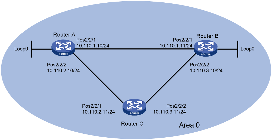
Use a pair of single-mode fibers (one Tx and one Rx) to directly connect the POS interfaces of Router A and Router B, Router A and Router C, and Router B and Router C through PPP. Each device uses the Open Shortest Path First (OSPF) protocol to connect to the other two devices. Configure the network to meet the following requirements:
· When the link between Router A and Router B is intact, the traffic forwarding path from Router A to Router B is Router A -> Router B.
· When Router A receives the multiplexer section remote defect indication (MS-RDI) signals from the peer Router B and the MS-RDI signals continue for 100ms, the physical state of the interface will be automatically set to down.
· When interface POS 2/1/1 on Router A is down, the traffic forwarding path from Router A to Router B is Router A—>Router C—>Router B.
Figure 1 Network diagram
Analysis
· To automatically set the physical state of the interface to down upon receiving an MS-RDI signal from the peer, configure the action to take when alarms are received on the current interface. An RDI alarm occurs if the device receives MS-RDI signals from the remote end.
· To ensure that the POS interface is shut down if the MS-RDI signal persists for 100ms rather than immediately upon receiving an MS-RDI signal from the peer, configure the physical state change suppression interval as 100ms on the POS interface.
Software versions used
This configuration example was created and verified on R9141P16 of the MSR5680-X3 device.
Restrictions and guidelines
When the POS interfaces of two routers are directly connected, configure one end to use the master clock mode and the other end to use the slave clock mode.
Procedures
Configuring Router A
1. Configure interfaces on Router A:
# Assign an IP address to interface POS 2/1/1 and enable PPP encapsulation on the interface.
<RouterA> system-view
[RouterA] interface pos 2/1/1
[RouterA-Pos2/1/1] ip address 10.110.1.10 255.255.255.0
[RouterA-Pos2/1/1] link-protocol ppp
# Set the clock mode to master on interface POS 2/1/1.
[RouterA-Pos2/1/1] clock master
# Configure POS 2/1/1 to go down when an RDI alarm occurs.
[RouterA-Pos2/1/1] alarm-detect rdi action link-down
# Set the physical state change suppression interval to 100 milliseconds. Then, the interface state can change to up or down 100 milliseconds after the POS interface comes up or goes down.
[RouterA-Pos2/1/1] link-delay msec 100
[RouterA-Pos2/1/1] quit
# Assign an IP address to interface POS 2/1/2 and enable PPP encapsulation on the interface.
[RouterA] interface pos 2/1/2
[RouterA-Pos2/1/2] ip address 10.110.2.10 255.255.255.0
[RouterA-Pos2/1/2] link-protocol ppp
# Set the clock mode to master on interface POS 2/1/2.
[RouterA-Pos2/1/2] clock master
[RouterA-Pos2/1/2] quit
2. Configure OSPF.
[RouterA] ospf
[RouterA-ospf-1] area 0
[RouterA-ospf-1-area-0.0.0.0] network 10.110.1.0 0.0.0.255
[RouterA-ospf-1-area-0.0.0.0] network 10.110.2.0 0.0.0.255
[RouterA-ospf-1-area-0.0.0.0] network 1.1.1.1 0.0.0.0
[RouterA-ospf-1-area-0.0.0.0] quit
[RouterA-ospf-1] quit
Configuring Router B
1. Configure interfaces on Router B:
# Assign an IP address to interface POS 2/1/1 and enable PPP encapsulation on the interface. Use the default clock mode (slave) on the interface.
<RouterB> system-view
[RouterB] interface pos 2/1/1
[RouterB-Pos2/1/1] ip address 10.110.1.11 255.255.255.0
[RouterB-Pos2/1/1] link-protocol ppp
[RouterB-Pos2/1/1] quit
# Assign an IP address to interface POS 2/1/2 and enable PPP encapsulation on the interface. Use the default clock mode (slave) on the interface.
[RouterB] interface pos 2/1/2
[RouterB-Pos2/1/2] ip address 10.110.3.10 255.255.255.0
[RouterB-Pos2/1/2] link-protocol ppp
[RouterB-Pos2/1/2] quit
2. Configure OSPF.
[RouterB] ospf
[RouterB-ospf-1] area 0
[RouterB-ospf-1-area-0.0.0.0] network 10.110.1.0 0.0.0.255
[RouterB-ospf-1-area-0.0.0.0] network 10.110.3.0 0.0.0.255
[RouterB-ospf-1-area-0.0.0.0] network 2.2.2.2 0.0.0.0
[RouterB-ospf-1-area-0.0.0.0] quit
[RouterB-ospf-1] quit
Configuring Router C
1. Configure interfaces on Router C:
# Assign an IP address to interface POS 2/1/1 and enable PPP encapsulation on the interface. Use the default clock mode (slave) on the interface.
<RouterC> system-view
[RouterC] interface pos 2/1/1
[RouterC-Pos2/1/1] ip address 10.110.2.11 255.255.255.0
[RouterC-Pos2/1/1] link-protocol ppp
[RouterC-Pos2/1/1] quit
# Assign an IP address to interface POS 2/1/1 and enable PPP encapsulation on the interface.
[RouterC] interface pos 2/1/2
[RouterC-Pos2/1/2] ip address 10.110.3.11 255.255.255.0
[RouterC-Pos2/1/2] link-protocol ppp
# Set the clock mode to master on interface POS 2/1/2.
[RouterC-Pos2/1/2] clock master
[RouterC-Pos2/1/2] quit
2. Configure OSPF.
[RouterC] ospf
[RouterC-ospf-1] area 0
[RouterC-ospf-1-area-0.0.0.0] network 10.110.2.0 0.0.0.255
[RouterC-ospf-1-area-0.0.0.0] network 10.110.3.0 0.0.0.255
[RouterC-ospf-1-area-0.0.0.0] quit
[RouterC-ospf-1] quit
Verifying the configuration
# After completing the preceding configuration, check the route information for IP address 2.2.2.2/32 on Router A. Verify that Router A communicates with Router B through a direct link.
<RouterA> display ip routing-table 2.2.2.2 verbose
Summary Count : 1
Destination: 2.2.2.2/32
Protocol: OSPF Process ID: 1
SubProtID: 0x1 Age: 04h20m37s
Cost: 1 Preference: 10
IpPre: N/A QosLocalID: N/A
Tag: 0 State: Active Adv
OrigTblID: 0x0 OrigVrf: default-vrf
TableID: 0x2 OrigAs: 0
NBRID: 0x26000002 LastAs: 0
AttrID: 0xffffffff Neighbor: 0.0.0.0
Flags: 0x1008c OrigNextHop: 10.110.1.11
Label: NULL RealNextHop: 10.110.1.11
BkLabel: NULL BkNextHop: N/A
Tunnel ID: Invalid Interface: Pos2/1/1
BkTunnel ID: Invalid BkInterface: N/A
FtnIndex: 0x0 TrafficIndex: N/A
Connector: N/A
# Configure interface POS 2/1/1 on Router A to go down when it continuously receives RDI alarms for 100 milliseconds.
<RouterA> display interface pos 2/1/1 brief
Brief information on interfaces in route mode:
Link: ADM - administratively down; Stby - standby
Protocol: (s) - spoofing
Interface Link Protocol Primary IP Description
Pos2/1/1 DOWN DOWN --
# When interface POS 2/1/1 on Router A is down, check the route information for IP address 2.2.2.2/32. Verify that Router A and Router B have switched to communicate through Router C.
<RouterA> display ip routing-table 2.2.2.2 verbose
Summary Count : 1
Destination: 2.2.2.2/32
Protocol: OSPF Process ID: 1
SubProtID: 0x1 Age: 04h20m37s
Cost: 2 Preference: 10
IpPre: N/A QosLocalID: N/A
Tag: 0 State: Active Adv
OrigTblID: 0x0 OrigVrf: default-vrf
TableID: 0x2 OrigAs: 0
NBRID: 0x26000002 LastAs: 0
AttrID: 0xffffffff Neighbor: 0.0.0.0
Flags: 0x1008c OrigNextHop: 10.110.2.11
Label: NULL RealNextHop: 10.110.2.11
BkLabel: NULL BkNextHop: N/A
Tunnel ID: Invalid Interface: Pos2/1/2
BkTunnel ID: Invalid BkInterface: N/A
FtnIndex: 0x0 TrafficIndex: N/A
Connector: N/A
Configuration files
· Router A:
#
interface Pos2/1/1
link-protocol ppp
clock master
ip address 10.110.1.10 255.255.255.0
alarm-detect rdi action link-down
link-delay msec 100
#
interface Pos2/1/2
link-protocol ppp
clock master
ip address 10.110.1.10 255.255.255.0
#
ospf 1
area 0.0.0.0
network 10.110.1.0 0.0.0.255
network 10.110.2.0 0.0.0.255
network 1.1.1.1 0.0.0.0
#
· Router B:
#
interface Pos2/1/1
link-protocol ppp
ip address 10.110.1.11 255.255.255.0
#
interface Pos2/1/2
link-protocol ppp
ip address 10.110.3.10 255.255.255.0
#
ospf 1
area 0.0.0.0
network 10.110.1.0 0.0.0.255
network 10.110.3.0 0.0.0.255
network 2.2.2.2 0.0.0.0
#
· Router C:
#
interface Pos2/1/1
link-protocol ppp
ip address 10.110.1.10 255.255.255.0
#
interface Pos2/1/2
link-protocol ppp
clock master
ip address 10.110.1.10 255.255.255.0
#
ospf 1
area 0.0.0.0
network 10.110.2.0 0.0.0.255
network 10.110.3.0 0.0.0.255
#
Example: Using optical fibers to directly connect HDLC-enabled POS interfaces
Network configuration

Software versions used
This configuration example was created and verified on R9141P16 of the MSR5680-X3 device.
Restrictions and guidelines
· Only physical POS interfaces can be assigned to an HDLC bundle.
· When the POS interfaces of two routers are directly connected, configure one end to use the master clock mode and the other end to use the slave clock mode.
Procedures
Configuring Router A
# Create HDLC link bundle interface 1 and assign an IP address to it.
<RouterA> system-view
[RouterA] interface hdlc-bundle 1
[RouterA-HDLC-bundle1] ip address 1.1.1.1 24
[RouterA-HDLC-bundle1] quit
# Set the clock mode to master and enable HDLC encapsulation on interface POS 2/1/1.
[RouterA] interface pos 2/1/1
[RouterA-Pos2/1/1] clock master
[RouterA-Pos2/1/1] link-protocol hdlc
# Assign interface POS 2/1/1 to HDLC link bundle 1.
[RouterA-Pos2/1/1] bundle id 1
[RouterA-Pos2/1/1] quit
# Set the clock mode to master and enable HDLC encapsulation on interface POS 2/1/2.
[RouterA] interface pos 2/1/2
[RouterA-Pos2/1/2] clock master
[RouterA-Pos2/1/2] link-protocol hdlc
# Assign interface POS 2/1/2 to HDLC link bundle 1.
[RouterA-Pos2/1/2] bundle id 1
[RouterA-Pos2/1/2] quit
Configuring Router B
# Create HDLC link bundle interface 1 and assign an IP address to it.
<RouterB> system-view
[RouterB] interface hdlc-bundle 1
[RouterB-HDLC-bundle1] ip address 1.1.1.2 24
[RouterB-HDLC-bundle1] quit
# Enable HDLC encapsulation on interface POS 2/1/1. Use the default clock mode (slave) on the interface.
[RouterB] interface pos 2/1/1
[RouterB-Pos2/1/1] link-protocol hdlc
# Assign interface POS 2/1/1 to HDLC link bundle 1.
[RouterB-Pos2/1/1] bundle id 1
[RouterB-Pos2/1/1] quit
# Enable HDLC encapsulation on interface POS 2/1/2. Use the default clock mode (slave) on the interface.
[RouterB] interface pos 2/1/2
[RouterB-Pos2/1/2] link-protocol hdlc
# Assign interface POS 2/1/2 to HDLC link bundle 1.
[RouterB-Pos2/1/2] bundle id 1
[RouterB-Pos2/1/2] quit
Verifying the configuration
# Verify that the HDLC link bundle interfaces on Router A and Router B can ping each other.
[RouterA] ping –a 1.1.1.1 1.1.1.2
Ping 1.1.1.2 (1.1.1.2) from 1.1.1.1: 56 data bytes, press CTRL_C to break
56 bytes from 1.1.1.2: icmp_seq=0 ttl=255 time=0.000 ms
56 bytes from 1.1.1.2: icmp_seq=1 ttl=255 time=0.000 ms
56 bytes from 1.1.1.2: icmp_seq=2 ttl=255 time=0.000 ms
56 bytes from 1.1.1.2: icmp_seq=3 ttl=255 time=0.000 ms
56 bytes from 1.1.1.2: icmp_seq=4 ttl=255 time=0.000 ms
--- Ping statistics for 1.1.1.2 ---
5 packet(s) transmitted, 5 packet(s) received, 0.0% packet loss
round-trip min/avg/max/std-dev = 0.000/0.000/0.000/0.000 ms
# Execute the display bundle hdlc-bundle command on Router A or Router B to view the bundle information for HDLC link bundle interface 1. Use Router A as an example.
[RouterA] display bundle hdlc-bundle 1 slot 2
Bundle: HDLC-bundle1, slot 2
Selected members: 2, Total bandwidth: 1244160 kbps
Member State Bandwidth(kbps) Priority
Pos2/1/1 Selected 622080 32768
Pos2/1/2 Selected 622080 32768
The output indicates that:
· Both POS 2/1/1 and POS 2/1/2 are Selected for load sharing.
· The bandwidth of the HDLC link bundle is 1244160 kbps, which is the sum of the bandwidths of the two POS interfaces.
· If one POS interface fails (for example, POS 2/1/1 of Router A is down), traffic can be transmitted through the other POS interface, enhancing link reliability.
Configuration files
· Router A:
#
interface pos 2/1/1
link-protocol hdlc
clock master
bundle id 1
#
interface pos 2/1/2
link-protocol hdlc
clock master
bundle id 1
#
interface hdlc-bundle 1
ip address 1.1.1.1 24
#
· Router B:
#
interface pos 2/1/1
link-protocol hdlc
bundle id 1
#
interface pos 2/1/2
link-protocol hdlc
bundle id 1
#
interface hdlc-bundle 1
ip address 1.1.1.2 24
Related documentation
· H3C MSR5680-X3 Router Configuration Guides (V9)
· H3C MSR5680-X3 Router Command References (V9)