- Table of Contents
-
- H3C Campus Fixed-Port Switches CLI-Based Quick Start Configuration Guide -6W102
- 01-H3C Devices CLI Reference
- 02-Login Management Quick Start Configuration Guide
- 03-Configuration File Management Quick Start Configruation Guide
- 04-Software Upgrade Quick Start Configuration Guide
- 05-Device Management Quick Start Configuration Guide
- 06-NTP Quick Start Configuration Guide
- 07-RBAC Quick Start Configuration Guide
- 08-IRF Quick Start Configuration Guide
- 09-Ethernet Interface Quick Start Configuration Guide
- 10-VLAN Quick Start Configuration Guide
- 11-Port Isolation Quick Start Configuration Guide
- 12-Loop Detection Quick Start Configuration Guide
- 13-QinQ Quick Start Configuration Guide
- 14-MAC Address Table Quick Start Configuration Guide
- 15-Ethernet Link Aggregation Quick Start Configuration Guide
- 16-Spanning Tree Quick Start Configuration Guide
- 17-DHCP Quick Start Configuration Guide
- 18-OSPF Quick Start Configuration Guide
- 19-Static Routing Quick Start Configuration Guide
- 20-Basic RIP Quick Start Configuration Guide
- 21-PBR Quick Start Configuration Guide
- 22-IGMP Snooping Quick Start Configuration Guide
- 23-Packet Filtering Quick Start Configuration Guide
- 24-QoS Quick Start Configuration Guide
- 25-IP Source Guard Quick Start Configuration Guide
- 26-SSH Quick Start Configuration Guide
- 27-Port Security Quick Start Configuration Guide
- 28-VRRP Quick Start Configuration Guide
- 29-PoE Quick Start Configuration Guide
- 30-Mirroring Quick Start Configuration Guide
- 31-Information Center Quick Start Configuration Guide
- 32-SNMP Quick Start Configuration Guide
- 33-Static Route-Based Public and Private Network Intercommunication Configuration Guide
- 34-LAN Networks Quick Start Configuration Guide
- 35-802.1X Quick Start Configuration Guide
- 36-AAA Quick Start Configuration Guide
- Related Documents
-
| Title | Size | Download |
|---|---|---|
| 33-Static Route-Based Public and Private Network Intercommunication Configuration Guide | 147.27 KB |
Static Route-Based Public and Private Network Intercommunication Configuration Guide
Copyright © 2025 New H3C Technologies Co., Ltd. All rights reserved.
No part of this manual may be reproduced or transmitted in any form or by any means without prior written consent of New H3C Technologies Co., Ltd.
Except for the trademarks of New H3C Technologies Co., Ltd., any trademarks that may be mentioned in this document are the property of their respective owners.
The information in this document is subject to change without notice.
Configuring static route-based public and private network intercommunication
Introduction
Network configuration
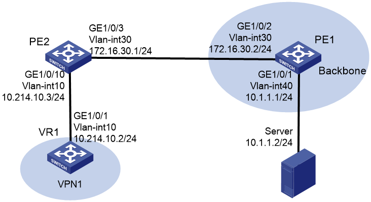
As shown in Figure 1, PE 1 is in the public network. The server is directly connected to PE 1. PE 2 is connected to VR 1. VPN 1 accesses the public network through PE 2. Configure
public and private network intercommunication to enable VR 1 to access Server.
Analysis
To enable VR 1 to access Server, configure the following settings in sequence:
1. Create VLANs on PE 1 and VR 1 and the associated VLAN interfaces.
2. Configure a VPN instance on PE 2 and connect VR 1 to PE 2.
3. Configure static routes on Server, PE 1, and VR 1 to ensure public network connectivity.
4. Configure static routes on PE 2 to implement public and private network intercommunication.
Procedure
Configuring VR 1
# Create VLAN 10 on VR 1, and assign GigabitEthernet 1/0/1 to VLAN 10.
<VR1> system-view
[VR1] vlan 10
[VR1-vlan10] quit
[VR1] interface GigabitEthernet 1/0/1
[VR1-GigabitEthernet1/0/1] port link-type trunk
[VR1-GigabitEthernet1/0/1] port trunk permit vlan 10
[VR1-GigabitEthernet1/0/1] undo port trunk permit vlan 1
[VR1-GigabitEthernet1/0/1] quit
# Configure the IP address of VLAN-interface 10 as 10.214.10.2/24.
[VR1] interface Vlan-interface 10
[VR1-Vlan-interface10] ip address 10.214.10.2 24
[VR1-Vlan-interface10] quit
Configuring PE 1
# Create VLAN 30 and VLAN 40 on PE 1, and assign GigabitEthernet 1/0/1 to VLAN 40 and GigabitEthernet 1/0/2 to VLAN 30.
<PE1> system-view
[PE1] vlan 30
[PE1-vlan30] quit
[PE1] vlan 40
[PE1-vlan40] quit
[PE1] interface GigabitEthernet 1/0/1
[PE1-GigabitEthernet1/0/1] port link-type trunk
[PE1-GigabitEthernet1/0/1] port trunk permit vlan 40
[PE1-GigabitEthernet1/0/1] undo port trunk permit vlan 1
[PE1-GigabitEthernet1/0/1] quit
[PE1] interface GigabitEthernet 1/0/2
[PE1-GigabitEthernet1/0/2] port link-type trunk
[PE1-GigabitEthernet1/0/2] port trunk permit vlan 30
[PE1-GigabitEthernet1/0/2] undo port trunk permit vlan 1
[PE1-GigabitEthernet1/0/2] quit
# Configure the IP addresses of VLAN-interface 30 and VLAN-interface 40 as 172.16.30.2/24 and 10.1.1.1/24, respectively.
[PE1] interface Vlan-interface 30
[PE1-Vlan-interface30] ip address 172.16.30.2 24
[PE1-Vlan-interface30] quit
[PE1] interface Vlan-interface 40
[PE1-Vlan-interface40] ip address 10.1.1.1 24
[PE1-Vlan-interface40] quit
Configuring PE 2
# Create VPN instance named vpn1 on PE 2, configure the RD value for the VPN instance as 10:1, and configure both the import and export route targets as 111:1.
<PE2> system-view
[PE2] ip vpn-instance vpn1
[PE2-vpn-instance-vpn1] route-distinguisher 10:1
[PE2-vpn-instance-vpn1] vpn-target 111:1
[PE2-vpn-instance-vpn1] quit
# Create VLAN 10 and VLAN 30 on PE 2, and assign GigabitEthernet 1/0/10 to VLAN 10 and GigabitEthernet 1/0/3 to VLAN 30.
[PE2] vlan 10
[PE2-vlan10] quit
[PE2] vlan 30
[PE2-vlan30] quit
[PE2] interface GigabitEthernet 1/0/10
[PE2-GigabitEthernet1/0/10] port link-type trunk
[PE2-GigabitEthernet1/0/10] port trunk permit vlan 10
[PE2-GigabitEthernet1/0/10] undo port trunk permit vlan 1
[PE2-GigabitEthernet1/0/10] quit
[PE2] interface GigabitEthernet 1/0/3
[PE2-GigabitEthernet1/0/3] port link-type trunk
[PE2-GigabitEthernet1/0/3] port trunk permit vlan 30
[PE2-GigabitEthernet1/0/3] undo port trunk permit vlan 1
[PE2-GigabitEthernet1/0/3] quit
# Associate interface VLAN-interface 10 with VPN instance vpn1, and configure the IP address as 10.214.10.3/24.
[PE2] interface Vlan-interface 10
[PE2-Vlan-interface10] ip binding vpn-instance vpn1
[PE2-Vlan-interface10] ip address 10.214.10.3 24
[PE2-Vlan-interface10] quit
# Configure the IP address of VLAN-interface 30 as 172.16.30.1/24.
[PE2] interface Vlan-interface 30
[PE2-Vlan-interface30] ip address 172.16.30.1 24
[PE2-Vlan-interface30] quit
Configuring static routes on Server, PE 1, and VR 1
# Configure a static route on Server with destination network address 10.214.10.0 and next hop address 10.1.1.1.
<Server> system-view
[Server] ip route-static 10.214.10.0 255.255.255.0 10.1.1.1
# Configure a static route on PE 1 with destination network address 10.214.10.0 and next hop address 172.16.30.1.
<PE1> system-view
[PE1] ip route-static 10.214.10.0 24 172.16.30.1
# Configure a static route on VR 1 with destination network address 10.1.1.0 and next hop address 10.214.10.3.
<VR1> system-view
[VR1] ip route-static 10.1.1.0 24 10.214.10.3
Configuring static routes on PE 2 to implement public and private network intercommunication
# Configure a static route on PE 2 with destination network address 10.214.10.0 and next hop address 10.214.10.2, and bind this route to VPN instance vpn1.
<PE2> system-view
[PE2] ip route-static 10.214.10.0 24 vpn-instance vpn1 10.214.10.2
# Configure a static route on PE 2 with destination network address 10.1.1.0 and next hop address 172.16.30.2, and bind this route to VPN instance vpn1.
[PE2] ip route-static vpn-instance vpn1 10.1.1.0 24 172.16.30.2 public
Verifying the configuration
# Display the routing information of VPN instance vpn1 on PE2.
[PE2] display ip routing-table vpn-instance vpn1
Destinations : 7 Routes : 7
Destination/Mask Proto Pre Cost NextHop Interface
10.214.10.0/24 Direct 0 0 10.214.10.3 Vlan10
10.214.10.3/32 Direct 0 0 127.0.0.1 InLoop0
127.0.0.0/8 Direct 0 0 127.0.0.1 InLoop0
127.0.0.1/32 Direct 0 0 127.0.0.1 InLoop0
172.16.30.0/24 Direct 0 0 172.16.30.1 Vlan30
172.16.30.1/32 Direct 0 0 127.0.0.1 InLoop0
10.1.1.0/24 Static 60 0 172.16.30.2 Vlan30
The output shows that the routing table of VPN 1 contains a static route pointing to the public network.
# Display the routing information on PE2.
[PE1] display ip routing-table
Destinations : 14 Routes : 14
Destination/Mask Proto Pre Cost NextHop Interface
0.0.0.0/32 Direct 0 0 127.0.0.1 InLoop0
100.100.11.1/32 Direct 0 0 127.0.0.1 InLoop0
127.0.0.0/8 Direct 0 0 127.0.0.1 InLoop0
127.0.0.0/32 Direct 0 0 127.0.0.1 InLoop0
127.0.0.1/32 Direct 0 0 127.0.0.1 InLoop0
127.255.255.255/32 Direct 0 0 127.0.0.1 InLoop0
172.16.30.0/24 Direct 0 0 172.16.30.2 Vlan30
172.16.30.0/32 Direct 0 0 172.16.30.2 Vlan30
172.16.30.2/32 Direct 0 0 127.0.0.1 InLoop0
172.16.30.255/32 Direct 0 0 172.16.30.2 Vlan30
10.214.10.0/24 Static 60 1 10.214.10.2 Vlan10
224.0.0.0/4 Direct 0 0 0.0.0.0 NULL0
224.0.0.0/24 Direct 0 0 0.0.0.0 NULL0
255.255.255.255/32 Direct 0 0 127.0.0.1 InLoop0
The output shows that a static route pointing to the private network have been added to the public network routing table.
# Ping Server on VR 1 to verify the network connectivity.
<VR1>ping 10.1.1.2
Ping 10.1.1.2 (10.1.1.2): 56 data bytes, press CTRL+C to break
56 bytes from 10.1.1.2: icmp_seq=0 ttl=255 time=3.880 ms
56 bytes from 10.1.1.2: icmp_seq=1 ttl=255 time=0.819 ms
56 bytes from 10.1.1.2: icmp_seq=2 ttl=255 time=0.658 ms
56 bytes from 10.1.1.2: icmp_seq=3 ttl=255 time=1.421 ms
56 bytes from 10.1.1.2: icmp_seq=4 ttl=255 time=0.722 ms
--- Ping statistics for 10.1.1.2 ---
5 packet(s) transmitted, 5 packet(s) received, 0.0% packet loss
round-trip min/avg/max/std-dev = 0.658/1.500/3.880/1.221 ms
Configuration files
· VR 1:
#
vlan 10
#
interface Vlan-interface10
ip address 10.214.10.2 255.255.255.0
#
interface GigabitEthernet1/0/1
port link-mode bridge
port link-type trunk
undo port trunk permit vlan 1
port trunk permit vlan 10
#
ip route-static 10.1.1.0 24 10.214.10.3
#
· PE 1:
#
vlan 30
#
vlan 40
#
interface Vlan-interface30
ip address 172.16.30.2 255.255.255.0
#
interface Vlan-interface40
ip address 10.1.1.1 255.255.255.0
#
interface GigabitEthernet1/0/1
port link-mode bridge
port link-type trunk
undo port trunk permit vlan 1
port trunk permit vlan 40
#
interface GigabitEthernet1/0/2
port link-mode bridge
port link-type trunk
undo port trunk permit vlan 1
port trunk permit vlan 30
#
ip route-static 10.214.10.0 24 172.16.30.1
#
· PE 2:
#
ip vpn-instance vpn1
route-distinguisher 10:1
vpn-target 111:1 import-extcommunity
vpn-target 111:1 export-extcommunity
#
vlan 10
#
vlan 30
#
interface Vlan-interface10
ip binding vpn-instance vpn1
ip address 10.214.10.3 255.255.255.0
#
interface Vlan-interface30
ip binding vpn-instance vpn1
ip address 172.16.30.1 255.255.255.0
#
interface GigabitEthernet1/0/3
port link-mode bridge
port link-type trunk
undo port trunk permit vlan 1
port trunk permit vlan 30
#
interface GigabitEthernet1/0/10
port link-mode bridge
port link-type trunk
undo port trunk permit vlan 1
port trunk permit vlan 10
#
ip route-static 10.214.10.0 24 vpn-instance v1 10.214.10.2
ip route-static vpn-instance v1 10.1.1.0 24 172.16.30.2 public
#
Related documentation
· Static routing configuration in the Layer 3—IP routing configuration guide for the device.
· Static routing commands in the Layer 3—IP routing command reference for the device.