- Table of Contents
-
- H3C Campus Fixed-Port Switches CLI-Based Quick Start Configuration Guide -6W102
- 01-H3C Devices CLI Reference
- 02-Login Management Quick Start Configuration Guide
- 03-Configuration File Management Quick Start Configruation Guide
- 04-Software Upgrade Quick Start Configuration Guide
- 05-Device Management Quick Start Configuration Guide
- 06-NTP Quick Start Configuration Guide
- 07-RBAC Quick Start Configuration Guide
- 08-IRF Quick Start Configuration Guide
- 09-Ethernet Interface Quick Start Configuration Guide
- 10-VLAN Quick Start Configuration Guide
- 11-Port Isolation Quick Start Configuration Guide
- 12-Loop Detection Quick Start Configuration Guide
- 13-QinQ Quick Start Configuration Guide
- 14-MAC Address Table Quick Start Configuration Guide
- 15-Ethernet Link Aggregation Quick Start Configuration Guide
- 16-Spanning Tree Quick Start Configuration Guide
- 17-DHCP Quick Start Configuration Guide
- 18-OSPF Quick Start Configuration Guide
- 19-Static Routing Quick Start Configuration Guide
- 20-Basic RIP Quick Start Configuration Guide
- 21-PBR Quick Start Configuration Guide
- 22-IGMP Snooping Quick Start Configuration Guide
- 23-Packet Filtering Quick Start Configuration Guide
- 24-QoS Quick Start Configuration Guide
- 25-IP Source Guard Quick Start Configuration Guide
- 26-SSH Quick Start Configuration Guide
- 27-Port Security Quick Start Configuration Guide
- 28-VRRP Quick Start Configuration Guide
- 29-PoE Quick Start Configuration Guide
- 30-Mirroring Quick Start Configuration Guide
- 31-Information Center Quick Start Configuration Guide
- 32-SNMP Quick Start Configuration Guide
- 33-Static Route-Based Public and Private Network Intercommunication Configuration Guide
- 34-LAN Networks Quick Start Configuration Guide
- 35-802.1X Quick Start Configuration Guide
- 36-AAA Quick Start Configuration Guide
- Related Documents
-
| Title | Size | Download |
|---|---|---|
| 24-QoS Quick Start Configuration Guide | 193.40 KB |
QoS Quick Start Configuration Guide
Copyright © 2025 New H3C Technologies Co., Ltd. All rights reserved.
No part of this manual may be reproduced or transmitted in any form or by any means without prior written consent of New H3C Technologies Co., Ltd.
Except for the trademarks of New H3C Technologies Co., Ltd., any trademarks that may be mentioned in this document are the property of their respective owners.
The information in this document is subject to change without notice.
Configuring IP rate limiting
Introduction
The following information uses an example to describe the basic procedure for configuring IP rate limiting.
Network configuration
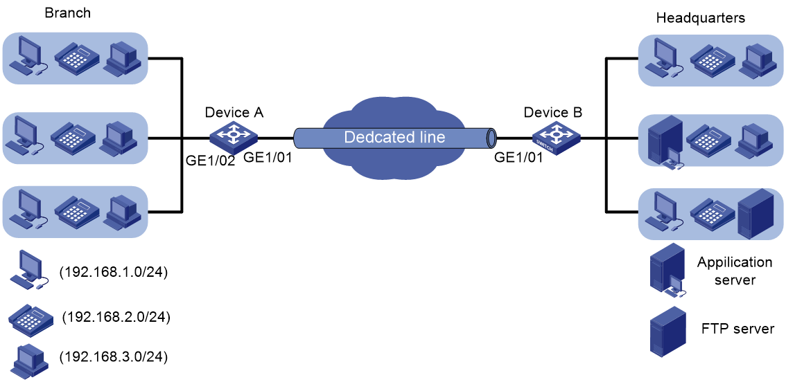
As shown in Figure 1, the 15-Mbps dedicated line transmits the FTP traffic, business-specific application traffic, and IP voice traffic between the headquarters and branch of a company.
The following traffic policing settings have been configured on the edge device (Device B) of the headquarters:
· CIR of 10 Mbps for IP voice traffic.
· CIR of 3 Mbps for business-specific application traffic.
· CIR of 7 Mbps for FTP traffic.
Configure traffic shaping on the edge device (Device A) of the branch to buffer excess traffic of each traffic type.
Configure rate limiting on Device A to limit the outgoing traffic rate to 15 Mbps.
Analysis
To meet the network requirements, you must perform the following tasks:
· To implement GTS, first determine the queue that transmits a type of traffic. In this example, the priorities of these types of traffic are not provided. You need to use priority marking to manually assign packets to different queues.
· You can manually assign packets to queues by marking DSCP values, 802.1p priority values, or local precedence values. To keep the contents of packets unchanged, mark local precedence values for packets.
Procedure
Before configuring GTS and rate limiting, make sure there is network connectivity between the branch and headquarters.
This section does not describe the configurations for enabling network connectivity.
Configuring priority marking
1. Create three traffic classes to match the three traffic types:
# Configure basic IPv4 ACL 2000 to match IP voice traffic (traffic from subnet 192.168.3.0/24).
<DeviceA> system-view
[DeviceA] acl basic 2000
[DeviceA-acl-ipv4-basic-2000] rule permit source 192.168.3.0 0.0.0.255
[DeviceA-acl-ipv4-basic-2000] quit
# Create a traffic class named voice, and use ACL 2000 as the match criterion.
[DeviceA] traffic classifier voice
[DeviceA-classifier-voice] if-match acl 2000
[DeviceA-classifier-voice] quit
# Configure basic IPv4 ACL 2001 to match application traffic (traffic from subnet 192.168.2.0/24).
[DeviceA] acl basic 2001
[DeviceA-acl-ipv4-basic-2001] rule permit source 192.168.2.0 0.0.0.255
[DeviceA-acl-ipv4-basic-2001] quit
# Create a traffic class named service, and use ACL 2001 as the match criterion.
[DeviceA] traffic classifier service
[DeviceA-classifier-service] if-match acl 2001
[DeviceA-classifier-service] quit
# Configure advanced IPv4 ACL 3000 to match FTP traffic (traffic from subnet 192.168.1.0/24 and with destination port number 20).
[DeviceA] acl advanced 3000
[DeviceA-acl-ipv4-adv-3000] rule permit tcp destination-port eq 20 source 192.168.1.0 0.0.0.255
[DeviceA-acl-ipv4-adv-3000] quit
# Create a traffic class named ftp, and use ACL 3000 as the match criterion.
[DeviceA] traffic classifier ftp
[DeviceA-classifier-ftp] if-match acl 3000
[DeviceA-classifier-ftp] quit
2. Create three traffic behaviors:
# Create a behavior named voice, and configure the behavior to mark packets with local precedence 6 (corresponding to queue 6).
[DeviceA] traffic behavior voice
[DeviceA-behavior-voice] remark local-precedence 6
[DeviceA-behavior-voice] quit
# Create a behavior named service, and configure the behavior to mark packets with local precedence 4 (corresponding to queue 4).
[DeviceA] traffic behavior service
[DeviceA-behavior-service] remark local-precedence 4
[DeviceA-behavior-service] quit
# Create a behavior named ftp, and configure the behavior to mark packets with local precedence 2 (corresponding to queue 2).
[DeviceA] traffic behavior ftp
[DeviceA-behavior-ftp] remark local-precedence 2
[DeviceA-behavior-ftp] quit
3. Configure and apply a QoS policy:
# Create a QoS policy named shaping, and associate the three classes with their respective behaviors in the QoS policy.
[DeviceA] qos policy shaping
[DeviceA-qospolicy-shaping] classifier voice behavior voice
[DeviceA-qospolicy-shaping] classifier service behavior service
[DeviceA-qospolicy-shaping] classifier ftp behavior ftp
[DeviceA-qospolicy-shaping] quit
# Apply the QoS policy shaping to the inbound direction of GigabitEthernet 1/0/2.
[DeviceA] interface gigabitethernet 1/0/2
[DeviceA-GigabitEthernet1/0/2] qos apply policy shaping inbound
[DeviceA-GigabitEthernet1/0/2] quit
Configuring GTS
# Configure GTS on GigabitEthernet 1/0/1 to set the CIR to 10 Mbps for queue 6 (IP voice traffic).
[DeviceA] interface gigabitethernet 1/0/1
[DeviceA-GigabitEthernet1/0/1] qos gts queue 6 cir 10240
# Configure GTS on GigabitEthernet 1/0/1 to set the CIR to 3 Mbps for queue 4 (application traffic).
[DeviceA-GigabitEthernet1/0/1] qos gts queue 4 cir 3072
# Configure GTS on GigabitEthernet 1/0/1 to set the CIR to 7 Mbps for queue 2 (FTP traffic).
[DeviceA-GigabitEthernet1/0/1] qos gts queue 2 cir 7168
Configuring rate limiting
# Configure rate limiting on GigabitEthernet 1/0/1 to set the CIR to 15 Mbps for outgoing traffic.
[DeviceA-GigabitEthernet1/0/1] qos lr outbound cir 15360
Verify the configuration
# Display ACL application information for inbound packet filtering.
# Verify the priority marking settings of GigabitEthernet 1/0/2.
<Device> display qos policy interface inbound
Interface: GigabitEthernet1/0/2
Direction: Inbound
Policy: shaping
Classifier: voice
Operator: AND
Rule(s) :
If-match acl 2000
Behavior: voice
Marking:
Remark local-precedence 6
Classifier: service
Operator: AND
Rule(s) :
If-match acl 2001
Behavior: service
Marking:
Remark local-precedence 4
Classifier: ftp
Operator: AND
Rule(s) :
If-match acl 3000
Behavior: ftp
Marking:
Remark local-precedence 2
# Verify the GTS settings on GigabitEthernet 1/0/1.
<Device> display qos gts interface
Interface: GigabitEthernet1/0/1
Rule: If-match queue 6
CIR 10240 (kbps), CBS 640000 (Bytes)
Rule: If-match queue 4
CIR 3072 (kbps), CBS 192000 (Bytes)
Rule: If-match queue 2
CIR 7168 (kbps), CBS 448000 (Bytes)
# Verify the rate limiting settings on GigabitEthernet 1/0/1.
<Device> display qos lr interface
Interface: GigabitEthernet1/0/1
Direction: Outbound
CIR 15360 (kbps), CBS 960000 (Bytes)
Configuration files
#
acl basic 2000
rule 0 permit source 192.168.3.0 0.0.0.255
#
acl basic 2001
rule 0 permit source 192.168.2.0 0.0.0.255
#
acl advanced 3000
rule 0 permit tcp source 192.168.1.0 0.0.0.255 destination-port eq ftp-data
#
traffic classifier ftp operator and
if-match acl 3000
#
traffic classifier service operator and
if-match acl 2001
#
traffic classifier voice operator and
if-match acl 2000
#
traffic behavior ftp
remark local-precedence 2
#
traffic behavior service
remark local-precedence 4
#
traffic behavior voice
remark local-precedence 6
#
qos policy shaping
classifier voice behavior voice
classifier service behavior service
classifier ftp behavior ftp
#
interface GigabitEthernet1/0/1
port link-mode bridge
qos lr outbound cir 15360 cbs 960000
qos gts queue 6 cir 10240 cbs 640000
qos gts queue 4 cir 3072 cbs 192000
qos gts queue 2 cir 7168 cbs 448000
#
interface GigabitEthernet1/0/2
port link-mode bridge
qos apply policy shaping inbound
#
return
Related documentation
· ACL configuration in the ACL and QoS configuration guide for the device.
· ACL commands in the ACL and QoS command reference for the device.
Configuring class-based accounting
Introduction
The following information uses an example to describe the basic procedure for configuring class-based accounting.
Network configuration
As shown in Figure 2, packet loss occurs when the PC accesses the server.
Configure class-based accounting through a QoS policy on the switch to check whether the packets are dropped by the switch.

Procedure
# Create advance IPv4 ACL 3001, configure a rule to match the packets with source IP address 192.168.0.2 and destination IP address 192.168.0.1, and configure another rule to match the packets with source IP address 192.168.0.1 and destination IP address 192.168.0.2.
<Sysname> system-view
[Sysname] acl advanced 3001
[Sysname-acl-ipv4-adv-3001] rule 0 permit ip source 192.168.0.2 0 destination 192.168.0.241 0
[Sysname-acl-ipv4-adv-3001] rule 5 permit ip source 192.168.0.241 0 destination 192.168.0.2 0
[Sysname-acl-ipv4-adv-3001] quit
# Create a traffic class named aa, and use ACL 3001 as the match criterion.
[Sysname] traffic classifier aa
[Sysname-classifier-1] if-match acl 3001
[Sysname-classifier-1] quit
# Create a traffic behavior named aa, and configure a traffic class-based accounting action.
[Sysname] traffic behavior aa
[Sysname-behavior-1] accounting packet
[Sysname-behavior-1] quit
# Create a QoS policy named aa, and associate the traffic classes with the traffic behaviors in the QoS policy.
[Sysname] qos policy aa
[Sysname-qospolicy-aa] classifier aa behavior aa
[Sysname-qospolicy-aa] quit
# Apply the QoS policy aa to the inbound and outbound directions of GigabitEthernet 1/0/1 and GigabitEthernet 1/0/2.
[Sysname] interface gigabitethernet 1/0/1
[Sysname-GigabitEthernet1/0/1] qos apply policy 1 inbound
[Sysname-GigabitEthernet1/0/1] qos apply policy 1 outbound
[Sysname-GigabitEthernet1/0/1] quit
[Sysname] interface gigabitethernet 1/0/2
[Sysname-GigabitEthernet1/0/2] qos apply policy 1 inbound
[Sysname-GigabitEthernet1/0/2] qos apply policy 1 outbound
[Sysname-GigabitEthernet1/0/2] quit
Verify the configuration
# Verify that the server can be successfully pinged from the PC.
C:\Users\user>ping 192.168.0.1
Pinging 192.168.0.1 with 32 bytes of data:
Reply from 192.168.0.1: bytes=32 time=3ms TTL=255
Reply from 192.168.0.1: bytes=32 time=1ms TTL=255
Reply from 192.168.0.1: bytes=32 time=1ms TTL=255
Reply from 192.168.0.1: bytes=32 time=1ms TTL=255
Ping statistics for 192.168.1.0:
Packets: Sent = 4, Received = 4, Lost = 0 (0% loss),
Approximate round trip times in milli-seconds:
Minimum = 1ms, Maximum = 3ms, Average = 1ms
# Verify that the switch forwards all packets from the PC.
[Sysname] display qos policy interface
Interface: GigabitEthernet1/0/1
Direction: Inbound
Policy: aa
Classifier: aa
Operator: AND
Rule(s) :
If-match acl 3001
Behavior: aa
Accounting enable:
4 (Packets)
Interface: GigabitEthernet1/0/1
Direction: Outbound
Policy: aa
Classifier: aa
Operator: AND
Rule(s) :
If-match acl 3001
Behavior: aa
Accounting enable:
7 (Packets)
Interface: GigabitEthernet1/0/2
Direction: Inbound
Policy: aa
Classifier: aa
Operator: AND
Rule(s) :
If-match acl 3001
Behavior: aa
Accounting enable:
7 (Packets)
Interface: GigabitEthernet1/0/2
Direction: Outbound
Policy: aa
Classifier: aa
Operator: AND
Rule(s) :
If-match acl 3001
Behavior: aa
Accounting enable:
4 (Packets)
The output shows that the switch forwarded all packets from the PC (received four packets on GE 1/0/1 and sent four packets on GE 1/0/2).
Configuration files
#
traffic classifier aa operator and
if-match acl 3001
#
traffic behavior aa
accounting packet
#
qos policy aa
classifier aa behavior aa
#
interface GigabitEthernet1/0/1
port link-mode bridge
qos apply policy aa inbound
qos apply policy aa outbound
#
interface GigabitEthernet1/0/2
port link-mode bridge
qos apply policy aa inbound
qos apply policy aa outbound
#
acl number 3001
rule 0 permit ip source 192.168.0.2 0 destination 192.168.0.1 0
rule 5 permit ip source 192.168.0.1 0 destination 192.168.0.2 0
#
Related documentation
· QoS configuration in the ACL and QoS configuration guide for the device.
· QoS commands in the ACL and QoS command reference for the device.
Configuring denying inter-VLAN traffic
Introduction
The following information uses an example to describe the basic procedure for configuring denying inter-VLAN traffic.
Network configuration
As shown in Figure 3, the PC is in VLAN 10, and the server is in VLAN 20.
For security, configure QoS policies on GigabitEthernet 1/0/1 and GigabitEthernet 1/0/2 to deny traffic between the VLANs.

Analysis
To deny traffic from VLAN 10 to VLAN 20, apply a QoS policy to the inbound direction of GigabitEthernet 1/0/1.
To deny traffic from VLAN 2 to VLAN 10, apply a QoS policy to the inbound direction of GigabitEthernet 1/0/2.
Procedure
# Assign IP addresses to VLAN interfaces.
<Sysname> system-view
[Sysname] vlan 10
[Sysname-vlan10] port gigabitethernet 1/0/1
[Sysname-vlan10] quit
[Sysname] vlan 20
[Sysname-vlan20] port gigabitethernet 1/0/2
[Sysname-vlan20] quit
[Sysname] interface vlan-interface 10
[Sysname-Vlan-interface10] ip address 192.168.1.1 24
[Sysname-Vlan-interface10] quit
[Sysname] interface vlan-interface 20
[Sysname-Vlan-interface20] ip address 192.168.2.1 24
[Sysname-Vlan-interface20] quit
# Create advanced IPv4 ACL 3000, configure a rule to match the packets with the source IP address in the 192.168.1.0/24 network segment and the destination IP address in the 192.168.2.0/24 network segment.
<Sysname> system-view
[Sysname] acl advanced 3000
[Sysname-acl-ipv4-adv-3000] rule 0 permit ip source 192.168.1.0 0.0.0.255 destination 192.168.2.0 0.0.0.255
[Sysname-acl-ipv4-adv-3000] quit
# Create a traffic class named a1, and use ACL 3000 as the match criterion.
[Sysname] traffic classifier a1
[Sysname-classifier-a1] if-match acl 3000
[Sysname-classifier-a1] quit
# Create a traffic behavior named a2, and configure the deny action.
[Sysname] traffic behavior a2
[Sysname-behavior-a2] filter deny
[Sysname-behavior-a2] quit
# Create a QoS policy named a3, and associate the traffic class with the traffic behavior in the QoS policy.
[Sysname] qos policy a3
[Sysname-qospolicy-a3] classifier a1 behavior a2
[Sysname-qospolicy-a3] quit
# Apply the QoS policy to the inbound direction of GigabitEthernet 1/0/1.
[Sysname] interface gigabitethernet 1/0/1
[Sysname-GigabitEthernet1/0/1] qos apply policy a3 inbound
[Sysname-GigabitEthernet1/0/1] quit
# Create advanced IPv4 ACL 3001, configure a rule to match the packets with the source IP address in the 192.168.2.0/24 network segment and the destination IP address in the 192.168.1.0/24 network segment.
[Sysname] acl advanced 3001
[Sysname-acl-ipv4-adv-3001] rule 0 permit ip source 192.168.2.0 0.0.0.255 destination 192.168.1.0 0.0.0.255
[Sysname-acl-ipv4-adv-3001] quit
# Create a traffic class named b1, and use ACL 3001 as the match criterion.
[Sysname] traffic classifier b1
[Sysname-classifier-b1] if-match acl 3001
[Sysname-classifier-b1] quit
# Create a traffic behavior named b2, and configure the deny action.
[Sysname] traffic behavior b2
[Sysname-behavior-b2] filter deny
[Sysname-behavior-b2] quit
# Create a QoS policy named b3, and associate the traffic class with the traffic behavior in the QoS policy.
[Sysname] qos policy b3
[Sysname-qospolicy-b3] classifier b1 behavior b2
[Sysname-qospolicy-b3] quit
# Apply the QoS policy to the inbound direction of GigabitEthernet 1/0/2
[Sysname] interface gigabitethernet 1/0/2
[Sysname-GigabitEthernet1/0/2] qos apply policy b3 inbound
[Sysname-GigabitEthernet1/0/2] quit
Verify the configuration
# Verify that the server can be successfully pinged from the PC before the QoS policy is applied to the interface.
C:\Users\user>ping 192.168.2.2
Pinging 192.168.0.1 with 32 bytes of data:
Reply from 192.168.2.2: bytes=32 time=3ms TTL=255
Reply from 192.168.2.2: bytes=32 time=1ms TTL=255
Reply from 192.168.2.2: bytes=32 time=1ms TTL=255
Reply from 192.168.2.2: bytes=32 time=1ms TTL=255
Ping statistics for 192.168.2.2:
Packets: Sent = 4, Received = 4, Lost = 0 (0% loss),
Approximate round trip times in milli-seconds:
Minimum = 1ms, Maximum = 3ms, Average = 1ms
# Verify that the server cannot be successfully pinged from the PC after the QoS policy is applied to the interface.
C:\Users\user>ping 192.168.2.2
Pinging 192.168.2.2 with 32 bytes of data:
Request timed out.
Request timed out.
Request timed out.
Request timed out.
Ping statistics for 192.168.2.2:
Packets: Sent = 4, Received = 0, Lost = 4 (100% loss)
# Verify that the QoS policies applied to interfaces.
[Sysname] display qos policy interface
Interface: GigabitEthernet1/0/1
Direction: Inbound
Policy: a3
Classifier: a1
Operator: AND
Rule(s) :
If-match acl 3000
Behavior: a2
Filter enable: Deny
Interface: GigabitEthernet1/0/2
Direction: Inbound
Policy: b3
Classifier: b1
Operator: AND
Rule(s) :
If-match acl 3001
Behavior: b2
Filter enable: Deny
Configuration files
#
vlan 10
#
vlan 20
#
interface Vlan-interface10
ip address 192.168.1.1 255.255.255.0
#
interface Vlan-interface20
ip address 192.168.2.1 255.255.255.0
#
traffic classifier a1 operator and
if-match acl 3000
#
traffic classifier b1 operator and
if-match acl 3001
#
traffic behavior a2
filter deny
#
traffic behavior b2
filter deny
#
qos policy a3
classifier a1 behavior a2
#
qos policy b3
classifier b1 behavior b2
#
interface GigabitEthernet1/0/1
port link-mode bridge
port access vlan 10
qos apply policy a3 inbound
#
interface GigabitEthernet1/0/2
port link-mode bridge
port access vlan 20
qos apply policy b3 inbound
#
acl number 3000
rule 0 permit ip source 192.168.1.0 0.0.0.255 destination 192.168.2.0 0.0.0.255
#
#
acl number 3001
rule 0 permit ip source 192.168.2.0 0.0.0.255 destination 192.168.1.0 0.0.0.255
#
Related documentation
· ACL configuration in the ACL and QoS configuration guide for the device.
· ACL commands in the ACL and QoS command reference for the device.
· QoS configuration in the ACL and QoS configuration guide for the device.
· QoS commands in the ACL and QoS command reference for the device.