- Table of Contents
-
- H3C Campus Fixed-Port Switches CLI-Based Quick Start Configuration Guide -6W102
- 01-H3C Devices CLI Reference
- 02-Login Management Quick Start Configuration Guide
- 03-Configuration File Management Quick Start Configruation Guide
- 04-Software Upgrade Quick Start Configuration Guide
- 05-Device Management Quick Start Configuration Guide
- 06-NTP Quick Start Configuration Guide
- 07-RBAC Quick Start Configuration Guide
- 08-IRF Quick Start Configuration Guide
- 09-Ethernet Interface Quick Start Configuration Guide
- 10-VLAN Quick Start Configuration Guide
- 11-Port Isolation Quick Start Configuration Guide
- 12-Loop Detection Quick Start Configuration Guide
- 13-QinQ Quick Start Configuration Guide
- 14-MAC Address Table Quick Start Configuration Guide
- 15-Ethernet Link Aggregation Quick Start Configuration Guide
- 16-Spanning Tree Quick Start Configuration Guide
- 17-DHCP Quick Start Configuration Guide
- 18-OSPF Quick Start Configuration Guide
- 19-Static Routing Quick Start Configuration Guide
- 20-Basic RIP Quick Start Configuration Guide
- 21-PBR Quick Start Configuration Guide
- 22-IGMP Snooping Quick Start Configuration Guide
- 23-Packet Filtering Quick Start Configuration Guide
- 24-QoS Quick Start Configuration Guide
- 25-IP Source Guard Quick Start Configuration Guide
- 26-SSH Quick Start Configuration Guide
- 27-Port Security Quick Start Configuration Guide
- 28-VRRP Quick Start Configuration Guide
- 29-PoE Quick Start Configuration Guide
- 30-Mirroring Quick Start Configuration Guide
- 31-Information Center Quick Start Configuration Guide
- 32-SNMP Quick Start Configuration Guide
- 33-Static Route-Based Public and Private Network Intercommunication Configuration Guide
- 34-LAN Networks Quick Start Configuration Guide
- 35-802.1X Quick Start Configuration Guide
- 36-AAA Quick Start Configuration Guide
- Related Documents
-
| Title | Size | Download |
|---|---|---|
| 26-SSH Quick Start Configuration Guide | 1.22 MB |
SSH Quick Start Configuration Guide
Copyright © 2025 New H3C Technologies Co., Ltd. All rights reserved.
No part of this manual may be reproduced or transmitted in any form or by any means without prior written consent of New H3C Technologies Co., Ltd.
Except for the trademarks of New H3C Technologies Co., Ltd., any trademarks that may be mentioned in this document are the property of their respective owners.
The information in this document is subject to change without notice.
Contents
Configuring the device as an SSH server
Configuring SSH client client002
Configuring the device as an SSH client
Configuring RADIUS authentication and authorization for SSH users
Configuring HWTACACS authentication, authorization, and accounting for SSH users through ACS server
Configuring the HWTACACS server
Configuring local AAA authentication for SSH users
Configuring the device as an SSH server
Introduction
The following information uses an example to describe the basic procedure for configuring the device as an SSH server.
Network configuration
As shown in Figure 1, configure the switch to meet the following requirements:
· The switch acts as the SSH server and can reach SSH clients Host 1 and Host 2.
· Use password authentication to authenticate Host 1 locally, and use publickey authentication and the RSA public key algorithm to authenticate Host 2 locally.
· Set the username of Host 1 to client001 and password to hello12345 for login authentication. After the user logs in to the switch from the host, the user can use all commands to configure the switch.
· Set the username of Host 2 to client002 and use the RSA public key algorithm for login authentication. After the user logs in to the switch from the host, the user can use all commands to configure the switch.

Procedure
Configuring SSH client client002
# Generate RSA key pairs on the SSH client:
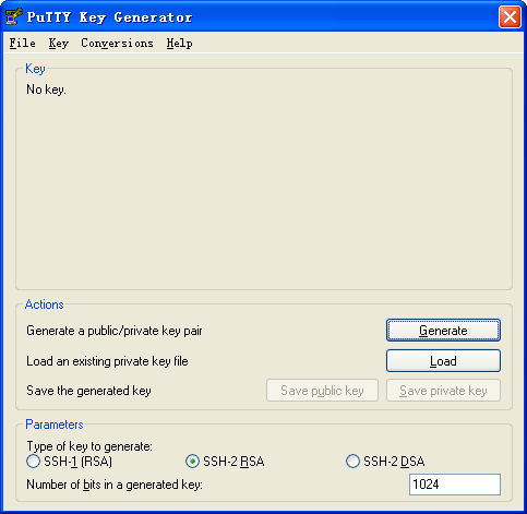
1. Run PuTTYGen.exe on the client, select SSH-2 RSA, and click Generate.
Figure 2 Generating a key pair on the client
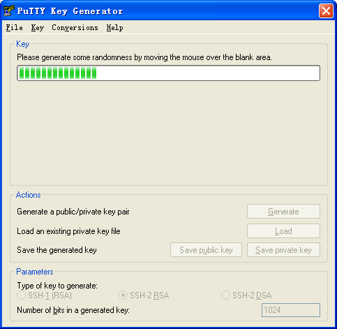
2. Continue moving the mouse during the key generating process, but do not place the mouse over the green progress bar shown in Figure 3. Otherwise, the progress bar stops moving and the key pair generating progress stops.
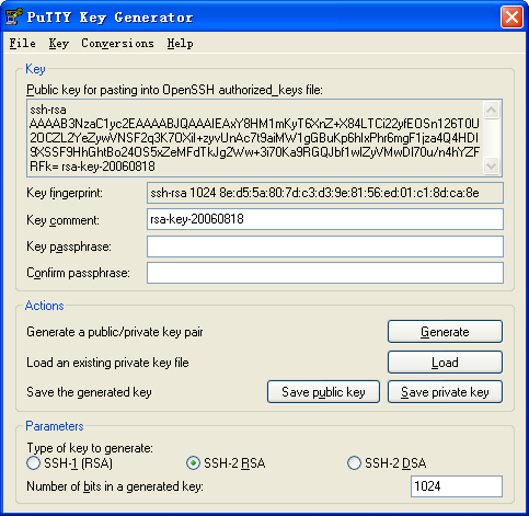
3. After the key pair is generated, click Save public key to save the public key.
A file saving window appears.
Figure 4 Saving a key pair on the client
4. Enter a file name (key.pub in this example), and click Save.
5. On the window shown in Figure 4, click Save private key to save the private key.
A confirmation dialog box appears.
6. Click Yes.
A file saving window appears.
Figure 5 Saving the key

7. Enter a file name (private.ppk in this example), and click Save.
8. Transmit the public key file to the server through FTP or TFTP. (Details not shown.)
Configuring the SSH server
# Generate an RSA key pair.
<Switch> system-view
[Switch] public-key local create rsa
The range of public key modulus is (512 ~ 4096).
If the key modulus is greater than 512, it will take a few minutes.
Press CTRL+C to abort.
Input the modulus length [default = 1024]:
Generating Keys...
..
Create the key pair successfully.
# Generate a DSA key pair.
[Switch] public-key local create dsa
The range of public key modulus is (512 ~ 2048).
If the key modulus is greater than 512, it will take a few minutes.
Press CTRL+C to abort.
Input the modulus length [default = 1024]:
Generating Keys...
......
Create the key pair successfully.
# Generate an ECDSA key pair.
[Switch] public-key local create ecdsa secp256r1
Generating Keys...
.
Create the key pair successfully.
# Enable the SSH server.
[Switch] ssh server enable
# Create VLAN 2 and assign Ten-GigabitEthernet 1/0/2 to VLAN 2.
[Switch] vlan 2
[Switch-vlan2] port ten-gigabitethernet 1/0/2
[Switch-vlan2] quit
# Assign an IP address to VLAN-interface 2. The SSH client uses this address as the destination for SSH connection.
[Switch] interface vlan-interface 2
[Switch-Vlan-interface2] ip address 192.168.1.40 255.255.255.0
[Switch-Vlan-interface2] quit
# Enable the login authentication mode to scheme for user lines VTY 0 through VTY 63.
[Switch] line vty 0 63
[Switch-line-vty0-63] authentication-mode scheme
[Switch-line-vty0-63] quit
# Create a local device management user named client001.
[Switch] local-user client001 class manage
New local user added.
# Set the password to hello12345 in plain text for local user client001.
[Switch-luser-manage-client001] password simple hello12345
# Authorize local user client001 to use the SSH service.
[Switch-luser-manage-client001] service-type ssh
# Assign the network-admin user role to local user client001.
[Switch-luser-manage-client001] authorization-attribute user-role network-admin
[Switch-luser-manage-client001] quit
# Import the peer public key from the public key file key.pub, and name it switchkey.
[Switch] public-key peer switchkey import sshkey key.pub
# Create an SSH user named client002. Specify the authentication method as publickey for the user. Assign the public key switchkey to the user.
[Switch] ssh user client002 service-type stelnet authentication-type publickey assign publickey switchkey
# Create a local device management user named client002.
[Switch] local-user client002 class manage
New local user added.
# Authorize local user client002 to use the SSH service.
[Switch-luser-manage-client002] service-type ssh
# Assign the network-admin user role to local user client002.
[Switch-luser-manage-client002] authorization-attribute user-role network-admin
[Switch-luser-manage-client002] quit
Verifying the configuration
Verify that client001 can log in to the SSH server through password authentication and client002 can log in to the SSH server through RSA publickey authentication:
1. Install the SSH client software on Host 1 and Host 2, respectively.
There are different types of SSH client software. This example uses an SSH client that runs PuTTY version 0.60 to verify the SSH login.
# Install PuTTY version 0.60 on the hosts.
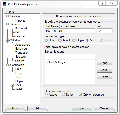
# Launch PuTTY.exe. The PuTTY Configuration window opens. Click Session.
¡ In the Host Name (or IP address) field, enter IP address 192.168.1.40 of the SSH server.
¡ In the Port field, enter 22.
¡ Select SSH as the connection type.
Figure 6 Configuring the SSH client

2. Verify that client001 can connect to the SSH server through password authentication:
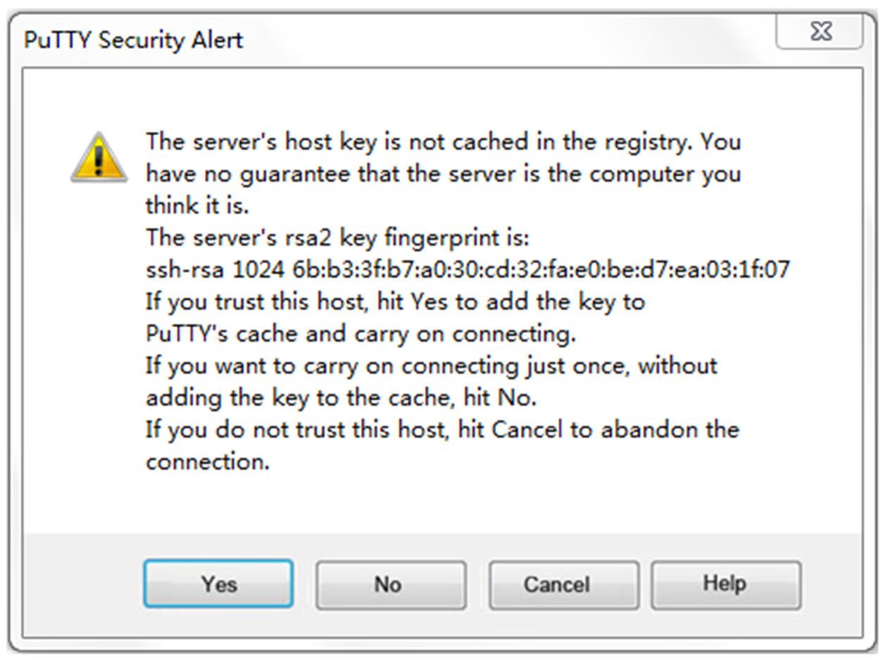
# Click Open in Figure 6. The PuTTY Security Alert dialog box opens.
Figure 7 PuTTY Security Alert

# Click Yes. Enter username client001 and password hello12345 (not shown on the interface) to log in to the SSH server.
Figure 8 Logging in to the SSH server
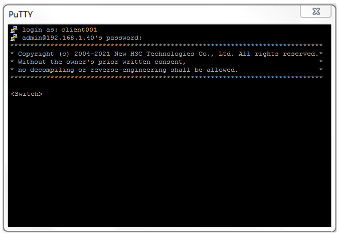
The output shows that client001 has successfully logged in to the switch and can use all commands available on the switch.
3. Verify that client002 can connect to the SSH server through RSA authentication:
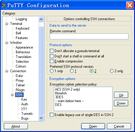
# On the PuTTY Configuration window, from the navigation tree, select Connection > SSH. The window shown in Figure 9 appears.
# Set Preferred SSH protocol version to 2.
Figure 9 Setting the preferred SSH version
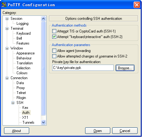
# From the navigation tree, select Connection > SSH > Auth. The window shown in Figure 10 appears.
# Click Browse… and select the private key file (private.ppk in this example).
# Click Open.
Figure 10 Specifying the private key file
# Entering username client002 to log in to the SSH server.
Configuration files
#
vlan 2
#
interface Vlan-interface2
ip address 192.168.1.40 255.255.255.0
#
interface Ten-GigabitEthernet1/0/2
port access vlan 2
#
line vty 0 63
authentication-mode scheme
#
ssh server enable
#
local-user client001 class manage
password hash $h$6$CqMnWdX6LIW/hz2Z$4+0Pumk+A98VlGVgqN3n/mEi7hJka9fEZpRZIpSNi9b
cBEXhpvIqaYTvIVBf7ZUNGnovFsqW7nYxjoToRDvYBg==
service-type ssh
authorization-attribute user-role network-admin
authorization-attribute user-role network-operator
#
public-key peer clientkey import sshkey key.pub
ssh user client002 service-type stelnet authentication-type publickey assign publickey ackey
#
local-user client002 class manage
service-type ssh
authorization-attribute user-role network-admin
#
Related documentation
· SSH configuration in the security configuration guide for the device.
· SSH commands in the security command reference for the device.
Configuring the device as an SSH client
Introduction
The following information uses an example to describe the basic procedure for configuring the device as an SSH client.
Network configuration
As shown in Figure 11, configure the switches to meet the following requirements:
· Switch A acts as the SSH client.
· Switch B acts as the SSH server and uses password authentication to authenticate the SSH client locally.
· Set the username of the client to client001 and password to hello12345 for login. After the user logs in to Switch B from Switch A, the user can use all commands to configure Switch B.

Procedure
1. Configure Switch A:
# Create VLAN 2 and assign Ten-GigabitEthernet 1/0/2 to VLAN 2.
<SwitchA> system-view
[SwitchA] vlan 2
[SwitchA-vlan2] port ten-gigabitethernet 1/0/2
[SwitchA-vlan2] quit
# Assign an IP address to VLAN-interface 2.
[SwitchA] interface vlan-interface 2
[SwitchA-Vlan-interface2] ip address 192.168.1.56 255.255.255.0
[SwitchA-Vlan-interface2] quit
2. Configure Switch B:
# Configure Switch B as the SSH server. For more information, see "Configuring the device as an SSH server."
Verifying the configuration
Verify that you can successfully log in to Switch B as a network administrator:
# On Switch A, establish an SSH connection to the SSH server (Switch B) at 192.168.1.40.
# Enter username client001 and enter Y to continue accessing the server without authenticating the server.
# Enter N to not save the server public key.
|
|
NOTE: If you enter Y to save the server public key, when the server public key changes, execute the delete SSH client server public key command in the system view of Switch A to delete the saved public key, so that you can establish a connection to the server again. |
# Enter password hello12345 (not shown on the interface) to log in to the SSH server.
<SwitchA> ssh2 192.168.1.40
Username: client001
Press CTRL+C to abort.
Connecting to 192.168.1.40 port 22.
The server is not authenticated. Continue? [Y/N]:Y
Do you want to save the server public key? [Y/N]:N
Enter password:
******************************************************************************
* Copyright (c) 2004-2021 New H3C Technologies Co., Ltd. All rights reserved.*
* Without the owner's prior written consent, *
* no decompiling or reverse-engineering shall be allowed. *
******************************************************************************
<SwitchB>
Configuration files
· Switch A
#
vlan 2
#
interface Vlan-interface2
ip address 192.168.1.56 255.255.255.0
#
interface Ten-GigabitEthernet1/0/2
port link-mode bridge
port access vlan 2
#
· Switch B
See "Configuration files."
Related documentation
· SSH configuration in the security configuration guide for the device.
· SSH commands in the security command reference for the device.
Configuring RADIUS authentication and authorization for SSH users
Introduction
The following information uses an example to describe the basic procedure for configuring RADIUS authentication and authorization for SSH users.
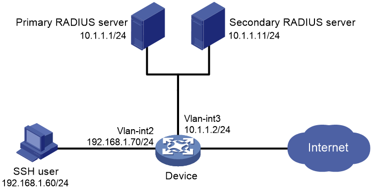
Network configuration
As shown in Figure 12, configure the NAS device (Device) and RADIUS servers to provide authentication and authorization on the SSH users that log in to the device. The specific requirements are as follows:
· Use two RADIUS servers to provide authentication and authorization services for secure logins of SSH users. Configure one server as the primary server and the other as the secondary server for authentication reliability.
· Add a user account with username hello@bbb and password aabbcc on each RADIUS server that runs IMC.
· Configure the device to include domain names in the usernames sent to the RADIUS servers, so as to identify the services to be provided to the users.
· Configure the device to permit the authenticated users to use the display commands of all system features and resources.
Procedure
Configuring RADIUS servers
In this example, RADIUS servers run IMC PLAT 7.0 (E0102) and IMC EIA 7.0 (E0201). This example describes the configuration of the primary RADIUS server. Configure the secondary RADIUS server in the same way the primary RADIUS server is configured.
Adding the device to IMC as an access device
1. Click the User tab.
2. From the navigation tree, select User Access Policy > Access Device Management > Access Device.
The access device list is displayed.
3. Click Add.
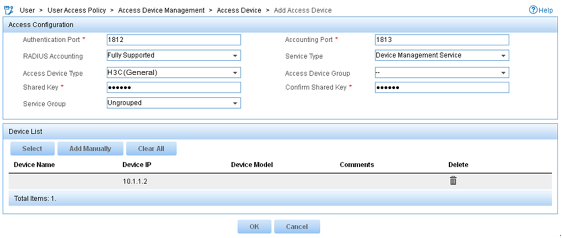
4. On the Add Access Device page, configure the following parameters:
¡ Enter 1812 and 1813 in the Authentication Port and Accounting Port fields, respectively.
¡ Enter expert in the Shared Key and Confirm Shared Key fields.
¡ Select Device Management Service from the Service Type list.
¡ Select H3C(General) from the Access Device Type list.
¡ Use the default values for other parameters in the Access Configuration area.
¡ In the Device List area, click Select or Add Manually to add the device (10.1.1.2) to IMC as an access device.
Figure 13 Adding an access device
5. Click OK.
Adding a device management user
1. Click the User tab.
2. From the navigation tree, select Access User > Device User.
The device management user list is displayed.
3. Click Add.
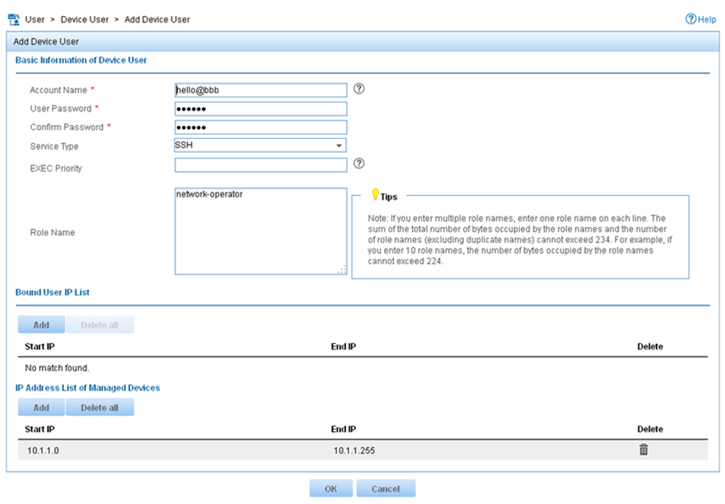
4. On the Add Device User page, configure the following parameters:
¡ Enter hello@bbb in the Account Name field.
¡ Enter aabbcc in the User Password and Confirm Password fields.
¡ Select SSH from the Service Type list.
¡ Enter network-operator in the Role Name field.
The network-operator user role has access to the display commands of all system features and resources.
¡ In the IP Address List of Managed Devices area, click Add to specify an IP segment (from 10.1.1.0 to 10.1.1.255) for management. The IP segment must contain the IP address of the access device.
Figure 14 Adding a device management user
5. Click OK.
Configuring the device
# Create VLAN 2 and assign Ten-GigabitEthernet 1/0/2 to the VLAN.
<Device> system-view
[Device] vlan 2
[Device-vlan2] port ten-gigabitethernet 1/0/2
[Device-vlan2] quit
# Assign an IP address to VLAN-interface 2.
[Device] interface vlan-interface 2
[Device-Vlan-interface2] ip address 192.168.1.70 255.255.255.0
[Device-Vlan-interface2] quit
# Create VLAN 3 and assign Ten-GigabitEthernet 1/0/1 to the VLAN.
[Device] vlan 3
[Device-vlan3] port ten-gigabitethernet 1/0/1
[Device-vlan3] quit
# Assign an IP address to VLAN-interface 3.
[Device] interface vlan-interface 3
[Device-Vlan-interface3] ip address 10.1.1.2 255.255.255.0
[Device-Vlan-interface3] quit
# Generate an RSA key pair.
[Device] public-key local create rsa
The range of public key modulus is (512 ~ 4096).
If the key modulus is greater than 512, it will take a few minutes.
Press CTRL+C to abort.
Input the modulus length [default = 1024]:
Generating Keys...
...........
Create the key pair successfully.
# Generate a DSA key pair.
[Device] public-key local create dsa
The range of public key modulus is (512 ~ 2048).
If the key modulus is greater than 512, it will take a few minutes.
Press CTRL+C to abort.
Input the modulus length [default = 1024]:
Generating Keys...
.......
Create the key pair successfully.
# Generate a local 256-bit ECDSA key pair.
[Device] public-key local create ecdsa secp256r1
Generating Keys...
Create the key pair successfully.
# Generate a local 384-bit ECDSA key pair.
[Device] public-key local create ecdsa secp384r1
Generating Keys...
.
Create the key pair successfully.
# Enable the SSH server.
[Device] ssh server enable
# Enable scheme authentication on VTY user lines 0 through 63.
[Device] line vty 0 63
[Device-line-vty0-63] authentication-mode scheme
[Device-line-vty0-63] quit
# Create a RADIUS scheme named rad.
[Device] radius scheme rad
# Specify the primary authentication RADIUS server with IP address 10.1.1.1 and port number 1812.
[Device-radius-rad] primary authentication 10.1.1.1 1812
# Specify the secondary authentication RADIUS server with IP address 10.1.1.11 and port number 1812.
[Device-radius-rad] secondary authentication 10.1.1.11 1812
# Specify the primary accounting RADIUS server with IP address 10.1.1.1 and port number 1813.
[Device-radius-rad] primary accounting 10.1.1.1 1813
# Specify the secondary accounting RADIUS server with IP address 10.1.1.11 and port number 1813.
[Device-radius-rad] secondary accounting 10.1.1.11 1813
# Set the authentication and accounting shared keys to expert in plain text for secure communication between the device and the RADIUS server.
[Device-radius-rad] key authentication simple expert
[Device-radius-rad] key accounting simple expert
# Include domain names in the usernames sent to the RADIUS server.
[Device-radius-rad] user-name-format with-domain
[Device-radius-rad] quit
# Create an ISP domain named bbb, and configure the ISP domain to use RADIUS scheme rad as the AAA methods of login users.
[Device] domain bbb
[Device-isp-bbb] authentication login radius-scheme rad
[Device-isp-bbb] authorization login radius-scheme rad
[Device-isp-bbb] accounting login radius-scheme rad
[Device-isp-bbb] quit
Verifying the configuration
# Initiate an SSH connection to the device, and enter username hello@bbb and password aabbcc. The user logs in to the device. (Details not shown.)
# Verify that the user can use the display commands of all system features and resources. (Details not shown.)
# Display RADIUS scheme configuration.
<Sysname> display radius scheme
Total 1 RADIUS schemes
------------------------------------------------------------------
RADIUS scheme name: rad
Index: 0
Primary authentication server:
Host name: Not Configured
IP : 10.1.1.1 Port: 1812
VPN : Not configured
State: Active
Test profile: Not configured
Weight: 0
Primary accounting server:
Host name: Not Configured
IP : 10.1.1.1 Port: 1813
VPN : Not configured
State: Active
Weight: 0
Second authentication server:
Host name: Not Configured
IP : 10.1.1.11 Port: 1812
VPN : Not configured
State: Active
Test profile: Not configured
Weight: 0
Second accounting server:
Host name: Not Configured
IP : 10.1.1.11 Port: 1813
VPN : Not configured
State: Active
Weight: 0
Accounting-On function : Disabled
extended function : Disabled
retransmission times : 50
retransmission interval(seconds) : 3
Timeout Interval(seconds) : 3
Retransmission Times : 3
Retransmission Times for Accounting Update : 5
Server Quiet Period(minutes) : 5
Realtime Accounting Interval(seconds) : 720
Stop-accounting packets buffering : Enabled
Retransmission times : 500
NAS IP Address : Not configured
VPN : Not configured
User Name Format : with-domain
Data flow unit : Byte
Packet unit : One
Attribute 15 check-mode : Strict
Attribute 25 : Standard
Attribute Remanent-Volume unit : Kilo
server-load-sharing : Disabled
Attribute 31 MAC format : HH-HH-HH-HH-HH-HH
Stop-accounting packets send-force : Disabled
Reauthentication server selection : Inherit
The output shows that the primary RADIUS server is in Active state.
# Shut down the primary RADIUS server. (Details not shown.)
# Display RADIUS scheme configuration again. Verify that the primary RADIUS server has changed to the Block state in the RADIUS scheme. The device starts to communicate with the secondary RADIUS server. (Details not shown.)
Configuration files
#
vlan 2 to 3
#
interface Vlan-interface2
ip address 192.168.1.70 255.255.255.0
#
interface Vlan-interface3
ip address 10.1.1.2 255.255.255.0
#
interface Ten-GigabitEthernet1/0/2
port link-mode bridge
port access vlan 2
#
interface Ten-GigabitEthernet1/0/1
port link-mode bridge
port access vlan 3
#
line vty 0 63
authentication-mode scheme
user-role network-operator
#
ssh server enable
#
radius scheme rad
primary authentication 10.1.1.1
primary accounting 10.1.1.1
secondary authentication 10.1.1.11
secondary accounting 10.1.1.11
key authentication cipher $c$3$GBZ1jhslcGwSOpSejsESMnOr8Gb8SIT5ew==
key accounting cipher $c$3$nGb/DWK8pxbHaLXQVc+xsmbUr1etIZVd7Q==
#
domain bbb
authentication login radius-scheme rad
authorization login radius-scheme rad
accounting login radius-scheme rad
#
Related documentation
· AAA configuration in the security configuration guide for the device.
· AAA commands in the security command reference for the device.
· SSH configuration in the security configuration guide for the device.
· SSH commands in the security command reference for the device.
Configuring HWTACACS authentication, authorization, and accounting for SSH users through ACS server
Introduction
The following information uses an example to describe the basic procedure for configuring HWTACACS authentication, authorization, and accounting for SSH users through an ACS server.
Network configuration
As shown in Figure 15, for the administrator to access the device securely from the host, establish an SSH connection between the host and the device. The specific requirements are as follows:
· Use a Cisco ACS server as the HWTACACS server to provide authentication and authorization services for secure logins of SSH users. Assign the highest level of privilege to an SSH user after the user passes authentication.
· Set the username of the SSH user to manager@bbb and password to 1234ab## for login to the device.
· Run an Stelnet client on the host as the SSH client.

Analysis
To meet the network requirements, you must perform the following tasks:
· Configure the SSH username and password on the HWTACACS server to identify valid users.
· For SSH users to perform AAA, set the authentication mode to scheme on VTY user lines.
· To support Stelnet clients that use different types of key pairs, generate RSA, DSA, and ECDSA key pairs on the device.
· Configure HWTACACS authentication and authorization by performing the following tasks on the device:
¡ Create an HWTACACS scheme.
¡ Specify the authentication and authorization servers.
¡ Apply the HWTACACS scheme to the ISP domain to which the SSH users belong on the device.
· Enable the default user role feature and specify network-admin as the default user role, so the authenticated users can have the highest level of privilege.
Procedure
Configuring the HWTACACS server
In this example, the server runs ACS 4.2. Before you perform the following tasks, make sure the host, the device, and the HWTACACS server can reach each other.
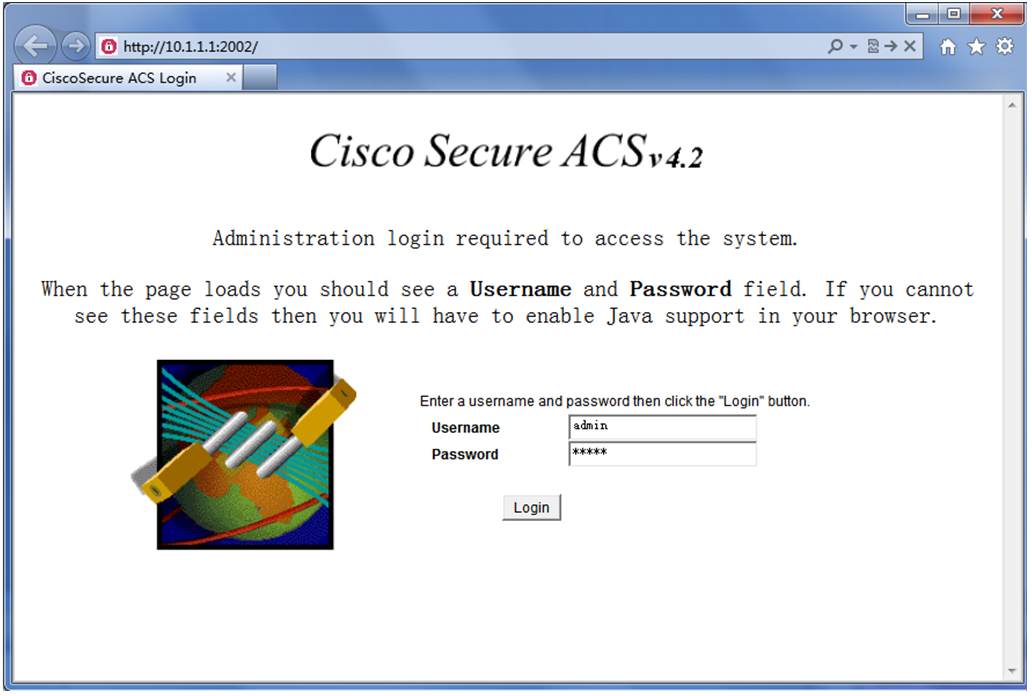
Logging in to the ACS server
# Enter the username and password, and click Login.
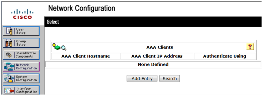
Adding a device to ACS
# In the navigation tree, click Network Configuration.
# Click Add Entry.
Figure 17 Adding an access device
# On the Add AAA Client page, configure the following parameters:
· Enter an AAA client hostname in the AAA Client Hostname field. This example uses Device.
· Enter 10.1.1.2 in the AAA Client IP Address field.
The IP address is the source IP address for outgoing HWTACACS packets on the device.
· Enter expert in the Shared Secret field.
The shared secret must be the same as the authentication, authorization, and accounting keys configured on the device for secure HWTACACS communication.
· Select TACACS+ (Cisco IOS) from the Authenticate Using list.
Figure 18 Adding an AAA client
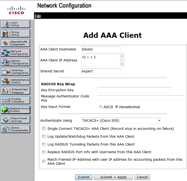
# Click Submit + Apply.
Adding a user
# In the navigation tree, click User Setup.
# On the User Setup page, enter manager in the User field and click Add/Edit.
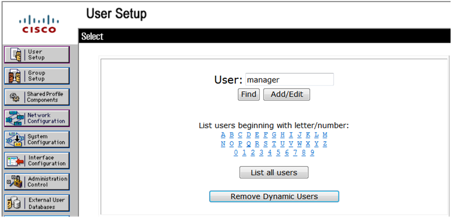
# Configure parameters for the user, including the user password and user group.
This example uses the default user group.
Figure 20 Configuring the user manager
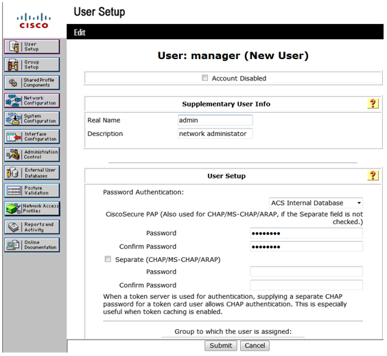
# Click Submit.
Configuring the device
# Create VLAN 2 and assign Ten-GigabitEthernet 1/0/2 to the VLAN.
<Device> system-view
[Device] vlan 2
[Device-vlan2] port ten-gigabitethernet 1/0/2
[Device-vlan2] quit
# Assign an IP address to VLAN-interface 2.
[Device] interface vlan-interface 2
[Device-Vlan-interface2] ip address 192.168.1.65 255.255.255.0
[Device-Vlan-interface2] quit
# Create VLAN 3 and assign Ten-GigabitEthernet 1/0/1 to the VLAN.
[Device] vlan 3
[Device-vlan3] port ten-gigabitethernet 1/0/1
[Device-vlan3] quit
# Assign an IP address to VLAN-interface 3.
[Device] interface vlan-interface 3
[Device-Vlan-interface3] ip address 10.1.1.2 255.255.255.0
[Device-Vlan-interface3] quit
# Generate an RSA key pair.
[Device] public-key local create rsa
The range of public key modulus is (512 ~ 4096).
If the key modulus is greater than 512, it will take a few minutes.
Press CTRL+C to abort.
Input the modulus length [default = 1024]:
Generating Keys...
...
Create the key pair successfully.
# Generate a DSA key pair.
[Device] public-key local create dsa
The range of public key modulus is (512 ~ 2048).
If the key modulus is greater than 512, it will take a few minutes.
Press CTRL+C to abort.
Input the modulus length [default = 1024]:
Generating Keys...
........
Create the key pair successfully.
# Generate a local 256-bit ECDSA key pair.
[Device] public-key local create ecdsa secp256r1
Generating Keys...
Create the key pair successfully.
# Generate a local 384-bit ECDSA key pair.
[Device] public-key local create ecdsa secp384r1
Generating Keys...
.
Create the key pair successfully.
# Enable the SSH server.
[Device] ssh server enable
# Enable scheme authentication on VTY user lines 0 through 63.
[Device] line vty 0 63
[Device-line-vty0-63] authentication-mode scheme
[Device-line-vty0-63] quit
# Enable the default user role feature and specify network-admin as the default user role.
[Device] role default-role enable network-admin
# Create an HWTACACS scheme named tac.
[Device] hwtacacs scheme tac
# Specify the primary HWTACACS authentication server with the IP address 10.1.1.1 and port number 49.
[Device-hwtacacs-tac] primary authentication 10.1.1.1 49
# Specify the shared key as expert for secure HWTACACS communication between the device and HWTACACS authentication server.
[Device-hwtacacs-tac] key authentication simple expert
# Specify the primary HWTACACS authorization server with the IP address 10.1.1.1 and port number 49.
[Device-hwtacacs-tac] primary authorization 10.1.1.1 49
# Specify the shared key as expert for secure HWTACACS communication between the device and HWTACACS authorization server.
[Device-hwtacacs-tac] key authorization simple expert
# Exclude domain names from the usernames sent to the HWTACACS server.
[Device-hwtacacs-tac] user-name-format without-domain
[Device-hwtacacs-tac] quit
# Create an ISP domain named bbb, and specify the domain to use HWTACACS scheme tac for authentication and authorization of login users. Specify the accounting method as none.
[Device] domain bbb
[Device-isp-bbb] authentication login hwtacacs-scheme tac
[Device-isp-bbb] authorization login hwtacacs-scheme tac
[Device-isp-bbb] accounting login none
[Device-isp-bbb] quit
Verifying the configuration
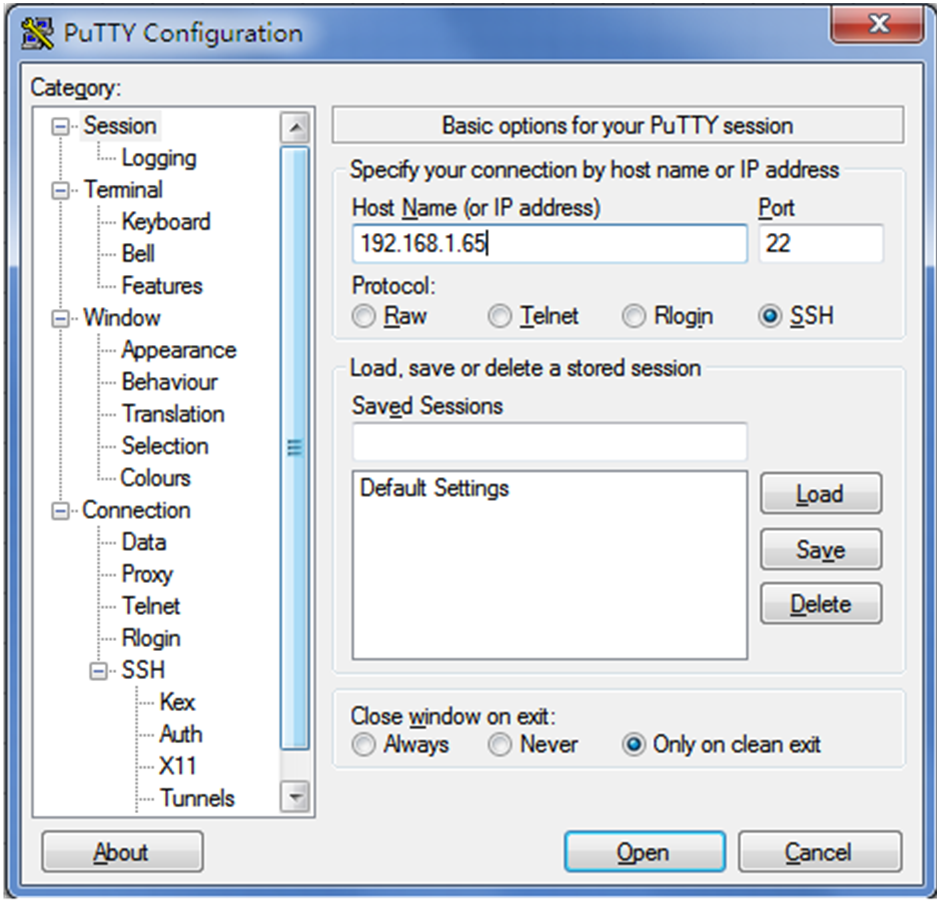
There are different types of SSH client software. This example uses an SSH client that runs PuTTY version 0.60 to verify the SSH login.
# Install PuTTY version 0.60 on the host.
# Launch PuTTY.exe. The PuTTY Configuration window opens. Click Session.
· In the Host Name (or IP address) field, enter IP address 192.168.1.65 of the SSH server.
· In the Port field, enter 22.
· Select SSH as the connection type.
Figure 21 Configuring the SSH client
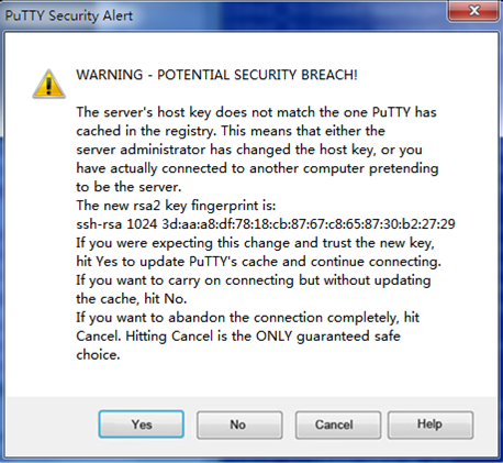
# Click Open. The PuTTY Security Alert dialog box opens. Click Yes.
Figure 22 PuTTY Security Alert
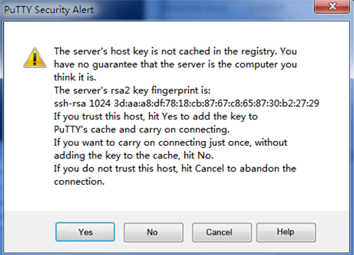
# Click Yes.
Figure 23 PuTTY Security Alert (2)
# Enter username manager@bbb and password 1234ab## to log in to the SSH server.
login as: manager@bbb
manager@[email protected]'s password:
******************************************************************************
* Copyright (c) 2004-2018 New H3C Technologies Co., Ltd. All rights reserved.*
* Without the owner's prior written consent, *
* no decompiling or reverse-engineering shall be allowed. *
******************************************************************************
<Device>
The output shows that the user has successfully logged in to the switch and can use all commands available on the switch.
Configuration files
#
vlan 2 to 3
#
interface Vlan-interface2
ip address 192.168.1.65 255.255.255.0
#
interface Vlan-interface3
ip address 10.1.1.2 255.255.255.0
#
interface Ten-GigabitEthernet1/0/2
port link-mode bridge
port access vlan 2
#
interface Ten-GigabitEthernet1/0/1
port link-mode bridge
port access vlan 3
#
line vty 0 63
authentication-mode scheme
user-role network-operator
#
ssh server enable
#
hwtacacs scheme tac
primary authentication 10.1.1.1
primary authorization 10.1.1.1
key authentication cipher $c$3$/9bCuPjMxjOtUvBx8NjtN+AnAsuLT2SrNA==
key authorization cipher $c$3$QF/fFJNv9IyKyFlsNOpeBYnDXArNhOvOdQ==
user-name-format without-domain
#
domain bbb
authentication login hwtacacs-scheme tac
authorization login hwtacacs-scheme tac
accounting login none
#
role default-role enable network-admin
#
Related documentation
· AAA configuration in the security configuration guide for the device.
· AAA commands in the security command reference for the device.
· SSH configuration in the security configuration guide for the device.
· SSH commands in the security command reference for the device.
Configuring local AAA authentication for SSH users
Introduction
The following information uses an example to describe the basic procedure for configuring local AAA authentication for SSH users.
Network configuration
As shown in Figure 24, configure the switch to meet the following requirements:
· The switch acts as the SSH server and uses local AAA authentication to authenticate the SSH client.
· Set the username of the client to client001 and password to hello12345 for login. After the user logs in to the switch from the host, the user can use all commands to configure the switch.

Procedure
# Create VLAN 2 and assign Ten-GigabitEthernet 1/0/2 to VLAN 2.
[Switch] vlan 2
[Switch-vlan2] port ten-gigabitethernet 1/0/2
[Switch-vlan2] quit
# Assign an IP address to VLAN-interface 2. The client uses this address as the destination address of the SSH connection.
[Switch] interface vlan-interface 2
[Switch-Vlan-interface2] ip address 192.168.1.40 255.255.255.0
[Switch-Vlan-interface2] quit
# Create local RSA and DSA key pairs.
<Switch> system-view
[Switch] public-key local create rsa
[Switch] public-key local create dsa
# Enable the SSH server.
[Switch] ssh server enable
# Enable scheme authentication for user lines VTY 0 through VTY 63.
[Switch] line vty 0 63
[Switch-line-vty0-63] authentication-mode scheme
[Switch-line-vty0-63] quit
# Create local user client001, and set the password, service type, and user role for the user to hello12345, SSH, and network-admin, respectively.
[Switch] local-user client001 class manage
New local user added.
[Switch-luser-manage-client001] password simple hello12345
[Switch-luser-manage-client001] service-type ssh
[Switch-luser-manage-client001] authorization-attribute user-role network-admin
[Switch-luser-manage-client001] quit
# Create an ISP domain named bbb and configure the domain to use local authentication for login users.
[Switch] domain bbb
[Switch-isp-bbb] authentication login local
[Switch-isp-bbb] quit
Verifying the configuration
There are different types of SSH client software. This example uses an SSH client that runs PuTTY version 0.60 to verify the SSH login.
# Install PuTTY version 0.60 on the host.
# Launch PuTTY.exe. The PuTTY Configuration window opens. Click Session.
· In the Host Name (or IP address) field, enter IP address 192.168.1.40 of the SSH server.
· In the Port field, enter 22.
· Select SSH as the connection type.
Figure 25 Configuring the SSH client
# Click Open. The PuTTY Security Alert dialog box opens.
Figure 26 PuTTY Security Alert
# Click Yes. Enter username client001 and password hello12345 (not shown on the interface) to log in to the SSH server.
Figure 27 Logging in to the SSH server

The output shows that the user has successfully logged in to the switch and can use all commands available on the switch.
Configuration files
#
vlan 2
#
interface Vlan-interface2
ip address 192.168.1.40 255.255.255.0
#
interface GigabitEthernet1/0/2
port link-mode bridge
port access vlan 2
#
line vty 0 63
authentication-mode scheme
user-role network-operator
#
ssh server enable
#
domain bbb
authentication login local
#
local-user client001 class manage
password hash $h$6$rLDGxBtUHlyovI15$k8yc//6l73h6CRK89jqTVf8Hu6VicbEl5EjUPqzykYj33YSQxPdHrSr+BIMeZUZDfsRAiy28ME9Vhb7VcVXpZw==
service-type ssh
authorization-attribute user-role network-admin
authorization-attribute user-role network-operator
#
Related documentation
· AAA configuration in the security configuration guide for the device.
· AAA commands in the security command reference for the device.
· SSH configuration in the security configuration guide for the device.
· SSH commands in the security command reference for the device.