- Table of Contents
-
- H3C Campus Fixed-Port Switches Web-Based Quick Start Configuration Guide-6W100
- 01-Compatible Product Models
- 02-Configuring Web Login with the Default IP
- 03-Web Login to a Device Without a Default IP
- 04-Interface Settings
- 05-PoE
- 06-VLAN
- 07-DHCP Server
- 08-DHCP Relay Agent
- 09-Static Routing
- 10-Policy-Based Routing
- 11-Ethernet Link Aggregation
- 12-Port Mirroring
- 13-Packet Filtering
- 14-Interface Rate Limit
- 15-Traffic Constrain
- 16-Spanning Tree
- 17-Direct Portal Authentication
- 18-Port Security
- 19-Port Isolation
- 20-ARP Attack Protection
- 21-Configuring a Static ARP Entry
- 22-IGMP Snooping
- 23-Enabling IPSG on an Interface
- 24-Software Upgrade
- 25-Adding Administrator Accounts
- 26-Ping and Tracert
- 27-Password Change
- 28-System Time
- 29-System Log
- 30-Configuration Backup, Export, Restoration to Factory Default
- 31-Device Reboot
- 32-Small-Sized Campus Network Configuration Guide
- Related Documents
-
| Title | Size | Download |
|---|---|---|
| 32-Small-Sized Campus Network Configuration Guide | 1.36 MB |
Small-Sized Campus Network Configuration Guide
Network configuration
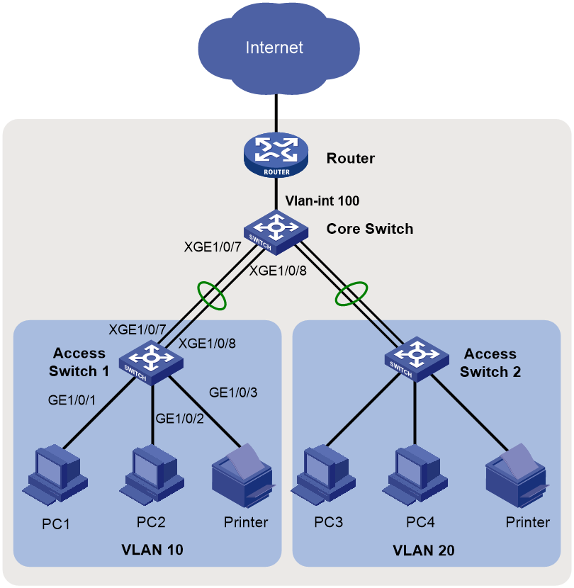
A small-sized campus usually uses the access-core networking mode and uses an MSR series router as the egress router, as shown in Figure 1.
· Enable STP on all switches to avoid loops.
· Configure link aggregation on both the access and core switches to ensure availability.
· Assign different service departments of the campus to different VLANs, and configure different departments to communicate with each other at Layer 3 through the core switch.
· Configure the core switch as the DHCP server to dynamically allocate IP addresses to users.
· Configure DHCP snooping on the access switches to prevent internal network users from obtaining IP addresses from unauthorized routers, and configure IP source guard on the access switches to prevent internal network users from changing IP addresses without permission.
Analysis and data preparation
The configuration workflow is as follows:
1. Log in to the web management interfaces of the devices.
2. Configure interfaces and VLANs.
3. Configure the core switch as the DHCP server.
4. Configure routing settings on the core switch.
5. Configure the egress router.
6. Configure DHCP snooping on the access switches.
7. Configure IP source guard on the access switches.
Table 1 Data preparation
|
Step |
Item |
Configuration |
Remarks |
|
1. Log in to the web management interfaces of the devices. |
Login through web |
Use the default settings to log in to the devices with a default IP address. For devices without a default IP address, log in to the devices through the console interface, and then configure the settings required for login through web. |
Log in to the devices through a browser on the PC. |
|
2. Configure interfaces and VLANs. |
Dynamic aggregation |
Access switch 1: uplink aggregate interface BAGG1 Core switch: downlink aggregate interface BAGG1 |
The access and core switches are connected through aggregate links. |
|
Port type |
Configure the interfaces connecting to PCs as access ports and the interfaces connecting to switches as trunk ports. |
N/A |
|
|
VLAN ID |
Access switch 1: VLAN 10 Access switch 2: VLAN 20 Core switch: VLANs 100, 10, and 20 |
Assign department A to VLAN 10 and department B to VLAN 20 to implement Layer 2 isolation. Connect the core switch to the egress router through VLAN-interface 100. |
|
|
3. Configure the core switch as the DHCP server. |
DHCP server |
N/A |
Configure the core switch as the DHCP server. |
|
Address pool |
VLAN 10: IP address pool 1 VLAN 20: IP address pool 2 |
Endpoints of department A obtain IP addresses from IP address pool 1, and endpoints of department B obtain IP addresses from IP address pool 2. |
|
|
Address allocation mode |
Global address pool |
N/A |
|
|
4. Configure routing settings on the core switch. |
IP address |
VLAN-interface 10: 10.10.10.1/24 VLAN-interface 20: 10.10.20.1/24 VLAN-interface 100: 10.10.100.1/24 |
VLAN-interface 100 connects the core switch to the egress router, enabling the internal network to communicate with the egress router. Configure a default route on the core switch, with the egress router as the next hop. After you configure IP addresses for VLAN-interface 10 and VLAN-interface 20 on the core switch, department A and department B can communicate with each other through the core switch. |
|
5. Configure the egress router. |
Public network interface IP address |
GE 1/0/2: 202.101.100.2/30 |
GE 1/0/2 is the public network interface, connecting the egress router to the Internet. |
|
Public network gateway |
202.101.100.1/30 |
Configure the IP address of the service provider's device connecting to the egress router as the public network gateway address. Configure a default route on the egress router, with the public network gateway address as the next hop, to forward internal network traffic to the Internet. |
|
|
DNS address |
202.101.100.199 |
The DNS server translates domain names into IP addresses. |
|
|
Internal network interface IP address |
GE 1/0/1: 10.10.100.2/24 |
GE 1/0/1 is the internal network interface, connecting the egress router to the internal network. |
|
|
6. Configure DHCP snooping on the access switches. |
Trusted port |
N/A |
Configure Layer 2 aggregate interface BAGG1 as a DHCP snooping trusted port. |
|
7. Configure IP source guard on the access switches. |
IP source guard |
N/A |
Configure IPv4SG bindings to bind IP addresses with MAC addresses. |
Configuration preparation
Log in to the web management interfaces of the devices.
For how to log in to the web management interface of a device with a default IP address, see "Configuring Web Login with the Default IP."
For how to log in to the web management interface of a device without a default IP address, see "Configuring Web Login without the Default IP."
For devices that support the web management interface and default IP address, see "Compatible Product Models."
Procedures
Configuring access switches
|
|
NOTE: This section uses the configuration of access switch 1 as an example. Configure access switch 2 in the same way you configure access switch 1. |
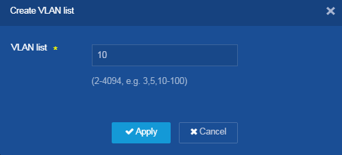
1. Configure VLANs:
a. From the left navigation pane, select Network > Links > VLAN.
b. Click the Add
icon ![]() at the upper right of the page to create a VLAN list.
at the upper right of the page to create a VLAN list.
c. Set the value for the VLAN list parameter to 10.
d. Click Apply.
Figure 2 Configuring VLANs
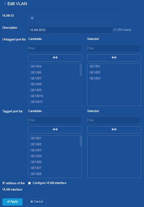
e. Click the ![]() icon
on the right of VLAN 10 to configure
the VLAN.
icon
on the right of VLAN 10 to configure
the VLAN.
f. Add interfaces GE 1/0/1, GE 1/0/2, and GE 1/0/3 to the untagged port list of VLAN 10.
g. Click Apply.
Figure 3 Configuring VLAN 10
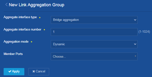
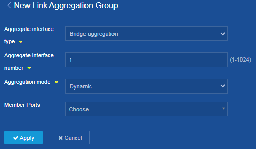
2. Configure the uplink aggregate interface:
a. From the left navigation pane, select Network > Interfaces > Link Aggregation.
b. Click the Add
icon ![]() at the upper right of the page to create an aggregation group.
at the upper right of the page to create an aggregation group.
c. Set the aggregate interface type to bridge aggregation.
d. Set the aggregate interface number to 1.
e. Set the aggregation mode to dynamic.
f. Select interfaces XGE 1/0/7 and XGE 1/0/8 as the member ports.
g. Click Apply.
Figure 4 Configuring Layer 2 link aggregation
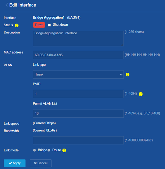
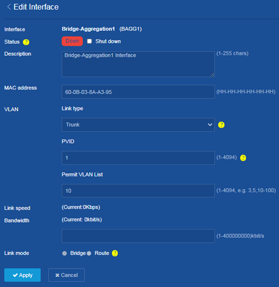
3. Configure VLAN attributes for the Layer 2 aggregate interface:
a. From the left navigation pane, select Network > Interfaces > Interfaces.
b. Click the ![]() icon
to configure Layer 2 aggregate interface 1.
icon
to configure Layer 2 aggregate interface 1.
c. Set the link type to trunk.
d. Set the value for the Permit VLAN list parameter to 10.
e. Click Apply.
Figure 5 Configuring VLAN attributes for the Layer 2 aggregate interface
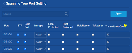
4. Configure STP settings:
a. From the left navigation pane, select Network > Links > STP.
b. Click the ![]() icon
on the right of Port settings to configure STP settings.
icon
on the right of Port settings to configure STP settings.
c. Select the box in the Edge Port column for interfaces GE 1/0/1, GE 1/0/2, and GE 1/0/3.
d. Click Apply.
Figure 6 Configuring STP settings
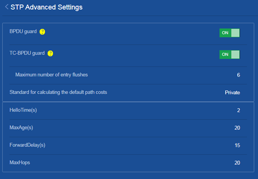
5. Enable BPDU guard:
a. From the left navigation pane, select Network > Links > STP.
b. Click the ![]() icon
on the right of Advanced settings to configure advanced STP settings.
icon
on the right of Advanced settings to configure advanced STP settings.
c. Select ON for the BPDU guard parameter to enable BPDU guard.
Figure 7 Enabling BPDU guard
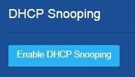
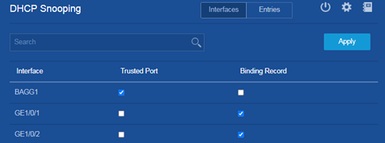
6. Configure DHCP snooping:
a. From the left navigation pane, select Network > Links > DHCP Snooping.
b. Click Enable DHCP Snooping.
Figure 8 Enabling DHCP snooping
c. Select the box in the Trusted Port column for interface BAGG1.
d. Select the box in the Binding Record column for interfaces GE 1/0/1 and GE 1/0/2.
e. Click Apply.
Figure 9 Configuring DHCP snooping
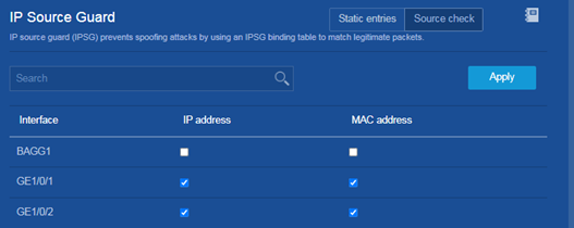
7. Configure IPv4SG bindings:
a. From the left navigation pane, select Security > Packet Filter > IP Source Guard.
b. Click Source check at the upper right of the IP Source Guard page.
c. Select the boxes in the IP address and MAC address columns for interfaces GE 1/0/1 and GE 1/0/2.
d. Click Apply.
Figure 10 Configure IPv4SG bindings
8. Click the ![]() icon
at the upper left of the page to save the configuration.
icon
at the upper left of the page to save the configuration.
Configuring the core switch
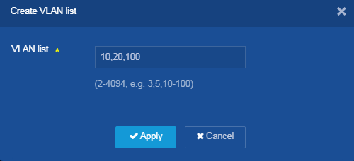
1. Configure VLANs:
a. From the left navigation pane, select Network > Links > VLAN.
b. Click the Add
icon ![]() at the upper right of the page to create a VLAN list.
at the upper right of the page to create a VLAN list.
c. Set the value for the VLAN list parameter to 10,20,100.
d. Click Apply.
Figure 11 Configuring VLANs
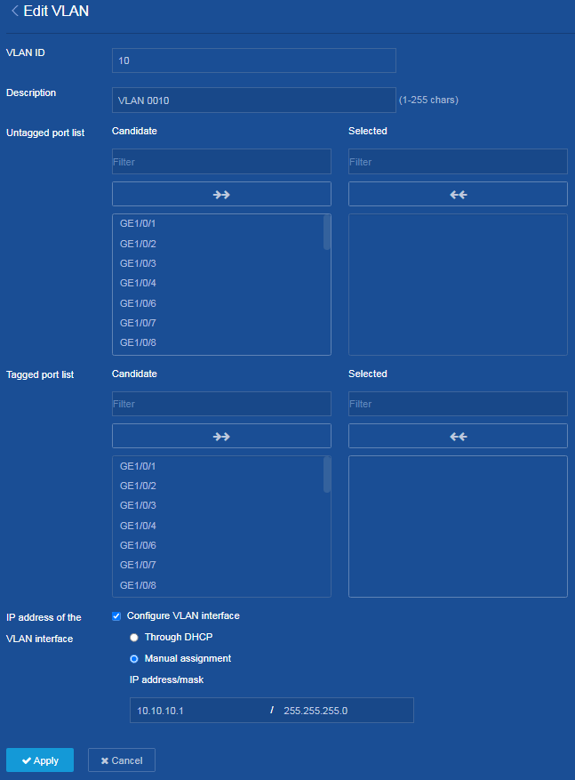
e. Configure VLAN 10:
# Click the ![]() icon on the right of VLAN 10 to configure the VLAN.
icon on the right of VLAN 10 to configure the VLAN.
# Select the Configure VLAN interface box for the IP address of the VLAN interface parameter, select Manual assignment, and set the IP address and subnet mask to 10.10.10.1 and 255.255.255.0, respectively.
# Click Apply.
Figure 12 Configuring VLAN 10
f. Configure VLAN 20:
# Click the ![]() icon on the right of VLAN 20 to configure the VLAN.
icon on the right of VLAN 20 to configure the VLAN.
# Select the Configure VLAN interface box for the IP address of the VLAN interface parameter, select Manual assignment, and set the IP address and subnet mask to 10.10.20.1 and 255.255.255.0, respectively.
# Click Apply.
g. Configure VLAN 100:
# Click the ![]() icon on the right of VLAN 100 to configure the VLAN.
icon on the right of VLAN 100 to configure the VLAN.
# Select the Configure VLAN interface box for the IP address of the VLAN interface parameter, select Manual assignment, and set the IP address and subnet mask to 10.10.100.1 and 255.255.255.0, respectively.
# Add interface GE 1/0/1 to the untagged port list of VLAN 100.
# Click Apply.
2. Configure the downlink aggregate interface:
a. From the left navigation pane, select Network > Interfaces > Link Aggregation.
¡ Click
the Add icon ![]() at the upper right of the page to create an aggregation group.
at the upper right of the page to create an aggregation group.
¡ Set the aggregate interface type to bridge aggregation.
¡ Set the aggregate interface number to 1.
¡ Set the aggregation mode to dynamic.
¡ Select interfaces XGE 1/0/7 and XGE 1/0/8 as the member ports.
¡ Click Apply.
Figure 13 Configuring Layer 2 link aggregation
3. Configure VLAN attributes for the Layer 2 aggregate interface:
a. From the left navigation pane, select Network > Interfaces > Interfaces.
b. Click the ![]() icon
to configure Layer 2 aggregate interface 1.
icon
to configure Layer 2 aggregate interface 1.
c. Set the link type to trunk.
d. Set the value for the Permit VLAN list parameter to 10.
e. Click Apply.
Figure 14 Configuring VLAN attributes for the Layer 2 aggregate interface
4. Configure the DHCP server:
a. From the left navigation pane, select Network > Service > DHCP.
b. Click Enable DHCP.
c. Click Address pool at the upper right of the page to configure DHCP address pools.
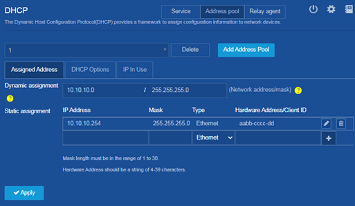
d. Click Add Address Pool to create address pool 1:
# On the Assigned Address tab, perform the following tasks:
- Set the network address and subnet mask for the Dynamic assignment parameter to 10.10.10.0 and 255.255.255.0, respectively.
- Set the values for the IP
Address, Mask, and Hardware Address/Client ID fields of the Static
assignment parameter to 10.10.10.254, 255.255.255.0,
and aabb-cccc-dd, respectively, and then click the ![]() icon.
icon.
Figure 15 Configuring address assignment settings for address pool 1
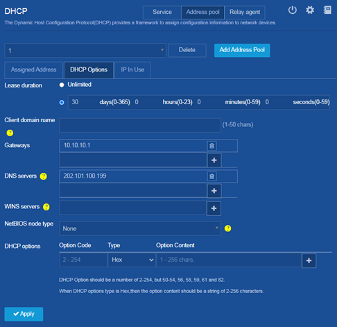
# On the DHCP Options tab, perform the following tasks:
- Set the lease duration to 30 days.
- Set the value for the Gateways parameter to 10.10.10.1, and then click the ![]() icon
on the right.
icon
on the right.
- Set the value for the DNS
servers parameter to 202.101.100.199, and then
click the ![]() icon
on the right.
icon
on the right.
# Click Apply.
Figure 16 Configuring DHCP options for address pool 1
e. Click Add Address Pool on the DHCP page to create address pool 2:
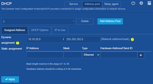
# On the Assigned Address tab, set the network address and subnet mask for the Dynamic assignment parameter to 10.10.20.0 and 255.255.255.0, respectively.
Figure 17 Configuring address assignment settings for address pool 2
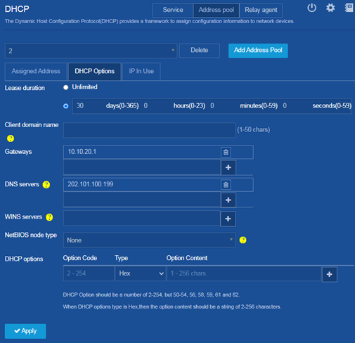
# On the DHCP Options tab, perform the following tasks:
- Set the lease duration to 30 days.
- Set the value for the Gateways parameter to 10.10.20.1, and then click the ![]() icon
on the right.
icon
on the right.
- Set the value for the DNS
servers parameter to 202.101.100.199, and then
click the ![]() icon
on the right.
icon
on the right.
# Click Apply.
Figure 18 Configuring DHCP options for address pool 2
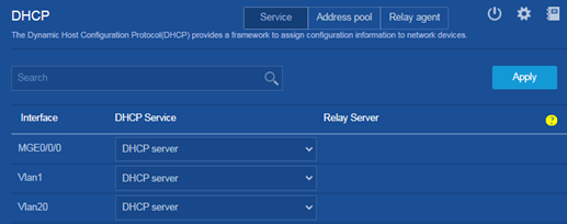
f. Click Service at the upper right of the page to configure DHCP services. By default, both VLAN-interface 10 and VLAN-interface 20 operate in DHCP server mode.
Figure 19 Configuring the interfaces to operate in DHCP server mode
5. Configure static routes:
a. From the left navigation pane, select Network > Routing > Static Routing.
b. Configure the ![]() icon
on the right of IPv4 static routes.
icon
on the right of IPv4 static routes.
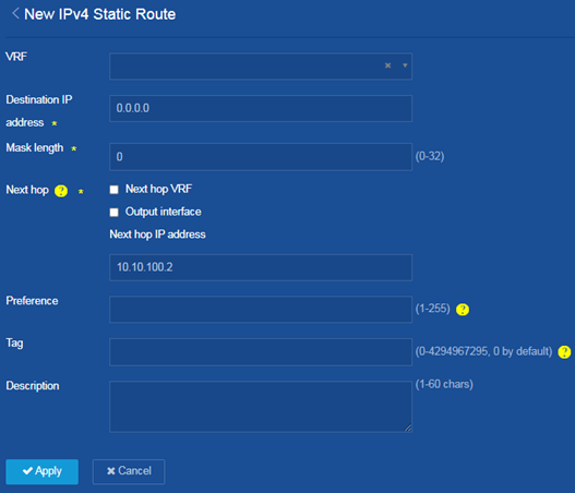
c. Click the Add
icon ![]() at the upper right of the page to create an IPv4 static route.
at the upper right of the page to create an IPv4 static route.
d. Set the destination IP address to 0.0.0.0, set the mask length to 0, unselect the Output interface box, and set the next hop IP address to 10.10.100.2.
This static route is used to forward internal network traffic to the egress router.
Figure 20 Configuring an IPv4 static route
6. Click the ![]() icon
at the upper left of the page to save the configuration.
icon
at the upper left of the page to save the configuration.
Configuring the egress router
1. Configure the IP address of the public network interface:
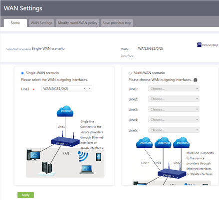
a. From the left navigation pane, select Network > WAN Settings.
b. On the Scene tab, perform the following tasks:
# Select the Single-WAN scenario.
# Select WAN2 (GE1/0/2) as the WAN outgoing interface.
# Click Apply.
Figure 21 Configuring scenario settings
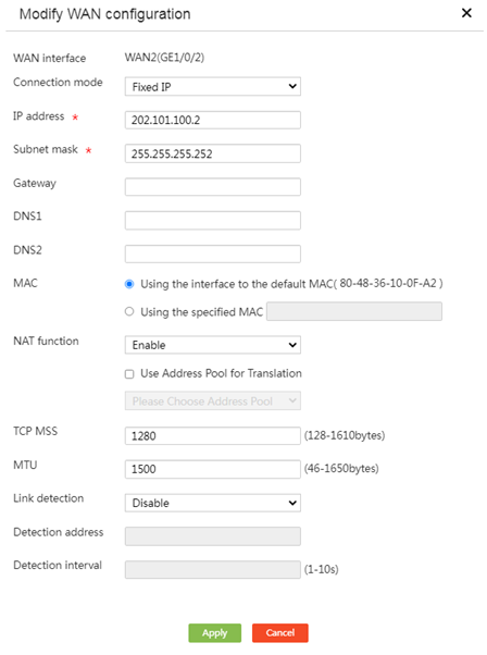
c. On the WAN Settings tab, perform the following tasks:
# Click the ![]() icon
for interface WAN2 (GE1/0/2) to configure the WAN settings.
icon
for interface WAN2 (GE1/0/2) to configure the WAN settings.
# Set the connection mode to fixed IP.
# Set the IP address to 202.101.100.2.
# Set the subnet mask to 255.255.255.252.
# Click Apply.
Figure 22 Configuring the IP address of the public network interface
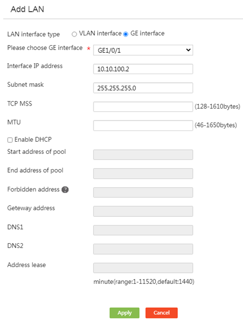
2. Configure the IP address of the internal network interface:
a. From the left navigation pane, select Network > LAN Settings.
b. Click Add on at the upper right of the page.
c. Set the LAN interface type to GE interface.
d. Select GE interface GE 1/0/1.
e. Set the interface IP address to 10.10.100.2.
f. Set the subnet mask to 255.255.255.0.
g. Click Apply.
Figure 23 Configuring the IP address of the internal network interface
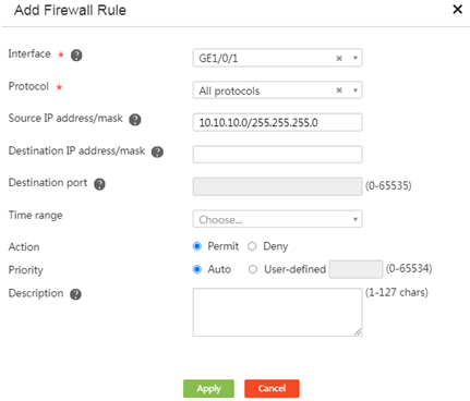
3. Configure firewall rules:
a. From the left navigation pane, select Network Security > Firewall.
b. Click Add to create the first firewall rule:
# Select interface GE 1/0/1.
# Select All protocols for the Protocol parameter.
# Set the source IP address and subnet mask to 10.10.10.0/255.255.255.0.
# Click Apply.
Figure 24 Configuring the first firewall rule
c. Click Add on the Firewall page to create the second firewall rule:
# Select interface GE 1/0/1.
# Select All protocols for the Protocol parameter.
# Set the source IP address and subnet mask to 10.10.20.0/255.255.255.0.
# Click Apply.
d. Click Add on the Firewall page to create the third firewall rule:
# Select interface GE 1/0/1.
# Select All protocols for the Protocol parameter.
# Set the source IP address and subnet mask to 10.10.100.0/255.255.255.0.
# Click Apply.
e. Click Add on the Firewall page to create the fourth firewall rule:
# Select interface GE 1/0/1.
# Select All protocols for the Protocol parameter.
# Set the source IP address and subnet mask to 0.0.0.0/0.0.0.0.
# Set the action to deny.
# Click Apply. This rule blocks other source addresses from the external network.
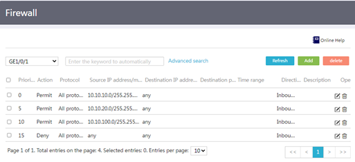
f. On the Firewall page, select interface GE1/0/1 to view all firewall rules configured for the interface.
Figure 25 Viewing all firewall rules of interface GE1/0/1
4. Configure routes to the internal network and the public network:
a. From the left navigation pane, select Advanced Settings > Static Routing.
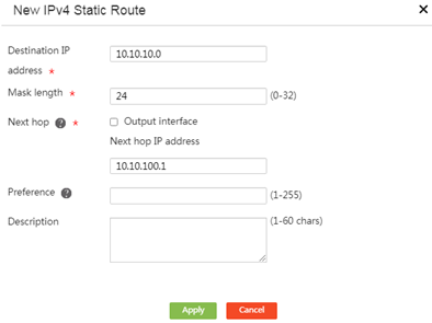
b. Click Add at the upper right of the page to create the first IPv4 static route:
# Set the destination IP address to 10.10.10.0.
# Set the mask length to 24.
# Unselect Output interface.
# Set the next hop IP address to 10.10.100.1.
# Click Apply.
Figure 26 Creating the first IPv4 static route
c. Click Add at the upper right of the Static Routing page to create the second IPv4 static route:
# Set the destination IP address to 10.10.20.0.
# Set the mask length to 24.
# Unselect Output interface.
# Set the next hop IP address to 10.10.100.1.
# Click Apply.
d. Click Add at the upper right of the Static Routing page to create the third IPv4 static route:
# Set the destination IP address to 0.0.0.0.
# Set the mask length to 0.
# Unselect Output interface.
# Set the next hop IP address to 202.101.100.1.
# Click Apply.
Saving the configuration
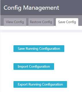
1. From the left navigation pane, select System Tool > Config Management.
2. Click the Save Config tab.
3. Click Save Running Configuration, save the running configuration to the next-startup configuration file or a specific file, and then click Apply.
Figure 27 Saving the configuration
Verifying the configuration
1. Verify that PCs in the same department (PC 1 and PC 2) can communicate with each other.
<PC1> ping 10.10.10.20
Ping 10.10.10.20 (10.10.10.20): 56 data bytes, press CTRL+C to break
56 bytes from 10.10.10.20: icmp_seq=0 ttl=255 time=1.015 ms
56 bytes from 10.10.10.20: icmp_seq=1 ttl=255 time=2.338 ms
56 bytes from 10.10.10.20: icmp_seq=2 ttl=255 time=1.951 ms
56 bytes from 10.10.10.20: icmp_seq=3 ttl=255 time=1.719 ms
56 bytes from 10.10.10.20: icmp_seq=4 ttl=255 time=1.629 ms
--- Ping statistics for 10.10.10.20 ---
5 packet(s) transmitted, 5 packet(s) received, 0.0% packet loss
round-trip min/avg/max/std-dev = 1.015/1.730/2.338/0.434 ms
2. Verify that PCs in different departments (PC 1 and PC 3) can communicate with each other.
<PC1> ping 10.10.20.10
Ping 10.10.20.10 (10.10.20.10): 56 data bytes, press CTRL+C to break
56 bytes from 10.10.20.10: icmp_seq=0 ttl=254 time=2.709 ms
56 bytes from 10.10.20.10: icmp_seq=1 ttl=254 time=0.877 ms
56 bytes from 10.10.20.10: icmp_seq=2 ttl=254 time=0.850 ms
56 bytes from 10.10.20.10: icmp_seq=3 ttl=254 time=0.805 ms
56 bytes from 10.10.20.10: icmp_seq=4 ttl=254 time=0.814 ms
--- Ping statistics for 10.10.20.10 ---
5 packet(s) transmitted, 5 packet(s) received, 0.0% packet loss
round-trip min/avg/max/std-dev = 0.805/1.211/2.709/0.749 ms
3. Verify that PCs in all departments (for example, PC 1) can communicate with the public network gateway. (Details not shown.)