- Table of Contents
-
- H3C Campus Fixed-Port Switches Web-Based Quick Start Configuration Guide-6W100
- 01-Compatible Product Models
- 02-Configuring Web Login with the Default IP
- 03-Web Login to a Device Without a Default IP
- 04-Interface Settings
- 05-PoE
- 06-VLAN
- 07-DHCP Server
- 08-DHCP Relay Agent
- 09-Static Routing
- 10-Policy-Based Routing
- 11-Ethernet Link Aggregation
- 12-Port Mirroring
- 13-Packet Filtering
- 14-Interface Rate Limit
- 15-Traffic Constrain
- 16-Spanning Tree
- 17-Direct Portal Authentication
- 18-Port Security
- 19-Port Isolation
- 20-ARP Attack Protection
- 21-Configuring a Static ARP Entry
- 22-IGMP Snooping
- 23-Enabling IPSG on an Interface
- 24-Software Upgrade
- 25-Adding Administrator Accounts
- 26-Ping and Tracert
- 27-Password Change
- 28-System Time
- 29-System Log
- 30-Configuration Backup, Export, Restoration to Factory Default
- 31-Device Reboot
- 32-Small-Sized Campus Network Configuration Guide
- Related Documents
-
| Title | Size | Download |
|---|---|---|
| 10-Policy-Based Routing | 110.37 KB |
IPv4 Local PBR Quick Start Configuration Guide
Network configuration
As shown in Figure 1, configure PBR on Switch A to forward all TCP packets to the next hop 1.1.2.2 (Switch B).

Procedure
Configuring Switch A
1. Configure VLAN interfaces and assign IP addresses to the interfaces:
From the left navigation pane, select Network > Links > VLAN.
¡ Click
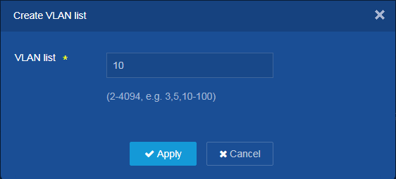
the Add icon ![]() to add a VLAN. Set the VLAN ID to 10. Click Apply.
to add a VLAN. Set the VLAN ID to 10. Click Apply.
Figure 2 Creating a VLAN
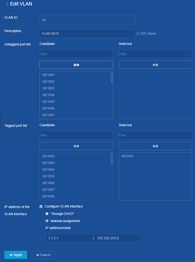
¡ Click
the ![]() icon next to VLAN 10 on the VLAN configuration page to edit the
VLAN.
icon next to VLAN 10 on the VLAN configuration page to edit the
VLAN.
¡ Add GE 1/0/1 connected to Switch B to the untagged port list.
¡ Select Configure VLAN interface for IP address of the VLAN interface.
¡ Set the IP address to 1.1.2.1 and mask length to 24.
¡ Click Apply.
¡ Configure VLAN-interface 20 and set its IP address. (Details not shown.)
Figure 3 Editing VLAN settings
2. Configure PBR settings:
From the left navigation pane, select Network > Routing > Policy-Based Routing.
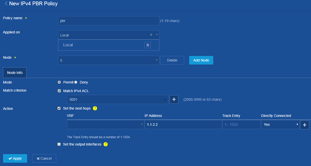
¡ On
the IPv4 PBR configuration page that opens, click the Add icon ![]() to
add an IPv4 PBR policy.
to
add an IPv4 PBR policy.
¡ Set the policy name to pbr.
¡ Select Local from the Applied on list.
¡ Click Add Node to add a node with number 5.
¡ Select Permit for Mode.
¡ Select
Match IPv4 ACL for Match criterion, and add the ![]() icon.
icon.
¡ Select the IPv4 ACL type in the dialog box that opens, and then click Apply.
¡ In the New IPv4 ACL dialog box that opens, select the advanced ACL category, set the ACL number to 3001, and then click Apply.
¡ In the New Rule for IPv4 Advanced ACL dialog box that opens, set the default permit action, set the IP protocol to 6 (TCP), clear the Continue to add next rule option, and then click Apply.
¡ Select Set the next hops for Action, and set the IP address to 1.1.2.2.
¡ Click Apply.
Figure 4 Adding an IPv4 PBR policy
3. Save the configuration:
Click the Save icon ![]() to save the configuration.
to save the configuration.
Configuring Switch B
Assign an IP address to each interface. (Details not shown.)
Configuring Switch C
Assign an IP address to each interface. (Details not shown.)
Verifying the configuration
1. Perform telnet operations to verify that local PBR on Switch A operates as configured to forward the matching TCP packets to the next hop 1.1.2.2 (Switch B), as follows:
# Verify that you can telnet to Switch B from Switch A successfully. (Details not shown.)
# Verify that you cannot telnet to Switch C from Switch A. (Details not shown.)
2. Verify that Switch A forwards packets other than TCP packets through VLAN-interface 20. For example, verify that you can ping Switch C from Switch A. (Details not shown.)