- Table of Contents
-
- H3C Campus Fixed-Port Switches Web-Based Quick Start Configuration Guide-6W100
- 01-Compatible Product Models
- 02-Configuring Web Login with the Default IP
- 03-Web Login to a Device Without a Default IP
- 04-Interface Settings
- 05-PoE
- 06-VLAN
- 07-DHCP Server
- 08-DHCP Relay Agent
- 09-Static Routing
- 10-Policy-Based Routing
- 11-Ethernet Link Aggregation
- 12-Port Mirroring
- 13-Packet Filtering
- 14-Interface Rate Limit
- 15-Traffic Constrain
- 16-Spanning Tree
- 17-Direct Portal Authentication
- 18-Port Security
- 19-Port Isolation
- 20-ARP Attack Protection
- 21-Configuring a Static ARP Entry
- 22-IGMP Snooping
- 23-Enabling IPSG on an Interface
- 24-Software Upgrade
- 25-Adding Administrator Accounts
- 26-Ping and Tracert
- 27-Password Change
- 28-System Time
- 29-System Log
- 30-Configuration Backup, Export, Restoration to Factory Default
- 31-Device Reboot
- 32-Small-Sized Campus Network Configuration Guide
- Related Documents
-
| Title | Size | Download |
|---|---|---|
| 16-Spanning Tree | 272.58 KB |
Configuring MSTP
Network configuration
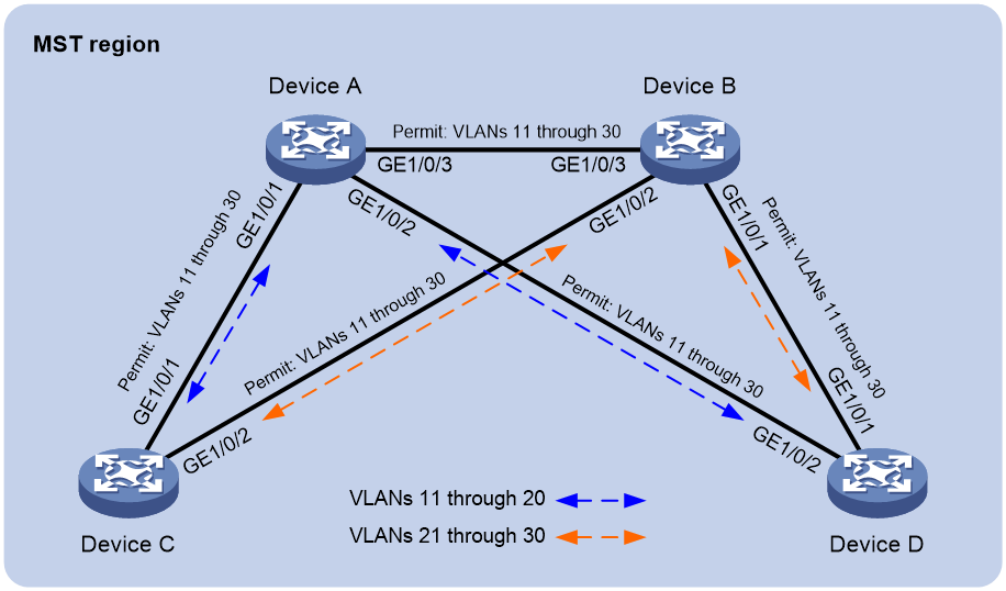
As shown in Figure 1, Device A and Device B operate at the core layer, and Device C and Device D operate at the distribution layer. The ports on the devices have the same path cost, and they all permit VLANs 11 through 30.
Configure MSTP to meet the following requirements:
· Device A, Device B, Device C, and Device D belong to the same MST region.
· MSTIs are used to share the traffic of VLANs 11 through 20 and of VLANs 21 through 30.
Analysis
To assign the devices to the same MST region, make sure the following MST region parameters are the same on the devices:
· Spanning tree mode (the default mode MSTP is used).
· Region name (test in this example).
· Revision level (the default value 0 is used).
· VLAN-to-instance mappings (VLANs 11 through 20 to MSTI 1, and VLANs 21 through 30 to MSTI 2).
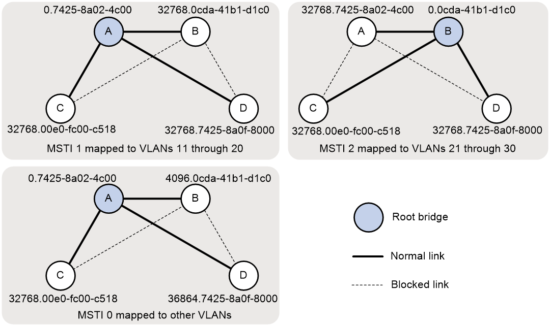
To use redundant links to share the traffic of different VLANs (as shown in Figure 2), perform the following tasks:
· Configure Device A as the root bridge of MSTI 1.
· Configure Device B as the root bridge of MIST 2.
· Assign priorities to Device A, Device B, Device C, and Device D in MSTI 0 in descending order for Device A to be the regional root bridge.
Figure 2 MSTIs mapped to different VLANs
Procedure
Configuring Device A
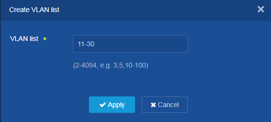
1. Create VLANs 11 through 30:
a. From the left navigation pane, select Network > Links > VLAN.
b. Click the Add icon ![]() to create VLANs 11 through 30.
to create VLANs 11 through 30.
c. Enter 11-30 in the VLAN list field.
d. Click Apply.
Figure 3 Creating VLANs
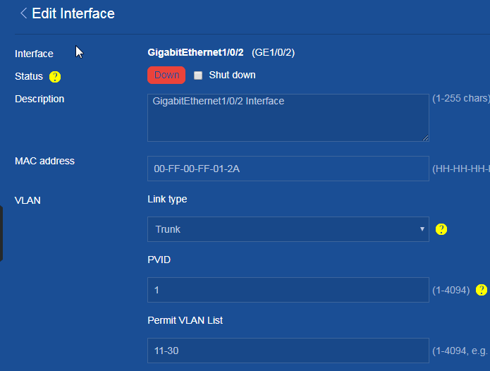
2. Configure GigabitEthernet 1/0/1, GigabitEthernet 1/0/2, and GigabitEthernet 1/0/3 to trunk VLANs 11 through 30:
a. From the left navigation pane, select Network > Interfaces > Interfaces.
b. Click the ![]() icon
next to GigabitEthernet 1/0/1.
icon
next to GigabitEthernet 1/0/1.
c. Set the link type to Trunk.
d. Enter 11-30 in the Permit VLAN List field.
e. Click Apply.
The system displays a success message after it configures VLAN parameters for the interfaces.
f. Configure GigabitEthernet 1/0/2 and GigabitEthernet 1/0/3 in the same way GigabitEthernet 1/0/1 is configured. (Details not shown.)
Figure 4 Configuring VLAN parameters
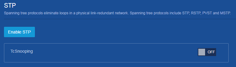
3. Enable STP:
a. From the left navigation pane, select Network > Links > STP.
b. Click Enable STP.
The default spanning tree mode is MSTP.
Figure 5 Enabling STP
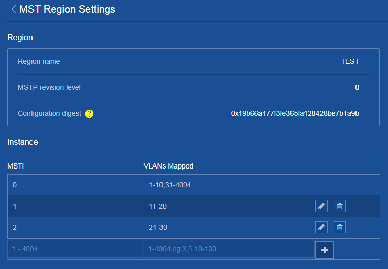
4. Configure the MST region name and VLAN-to-MSTI mapping:
a. Click the ![]() icon
next to MST region to access the MST Region Settings page.
icon
next to MST region to access the MST Region Settings page.
b. Configure the MST region name as Test.
c. Map VLANs 11 through 20 to MSTI 1.
d. Map VLANs 21 through 30 to MSTI 2, and set the MSTP revision level to 0.
e. Click the ![]() icon next
to MST Region Settings to return to the STP page.
icon next
to MST Region Settings to return to the STP page.
Figure 6 Configuring the MST region

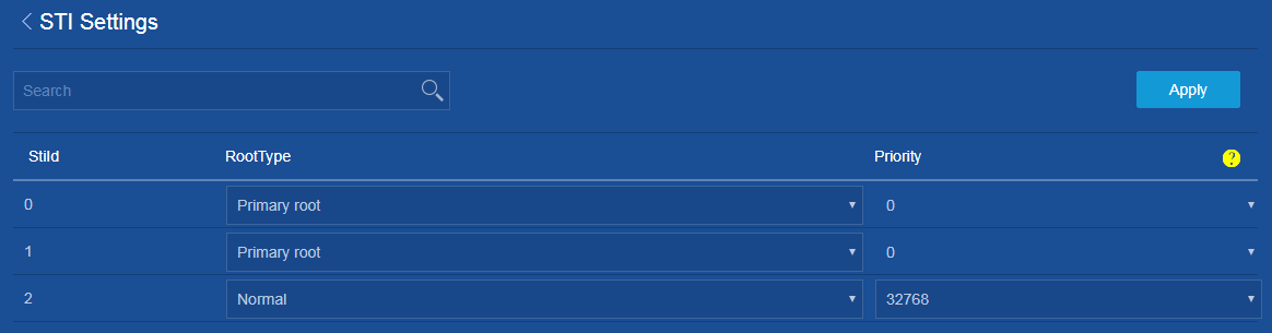
5. Configure Device A as the root bridge of MSTI 0 and MSTI 1:
a. Click the ![]() icon
next to MSTI settings to access the STI Settings page.
icon
next to MSTI settings to access the STI Settings page.
b. Set the root type for MSTI 0 to Primary root.
c. Set the root type for MSTI 1 to Primary root.
d. Click Apply.
The system displays a success message after it configures STI settings.
Figure 7 Configuring STI settings
6. Save the configuration:
Click the Save icon ![]() at the
upper left of the page.
at the
upper left of the page.
Configuring Device B
1. Create VLANs 11 through 30:
a. From the left navigation pane, select Network > Links > VLAN.
b. Click the Add icon ![]() to create
VLANs 11 through 30.
to create
VLANs 11 through 30.
c. Enter 11-30 in the VLAN list field.
d. Click Apply.
2. Configure GigabitEthernet 1/0/1, GigabitEthernet 1/0/2, and GigabitEthernet 1/0/3 to trunk VLANs 11 through 30:
a. From the left navigation pane, select Network > Interfaces > Interfaces.
b. Click the ![]() icon
next to GigabitEthernet 1/0/1.
icon
next to GigabitEthernet 1/0/1.
c. Set the link type to Trunk.
d. Enter 11-30 in the Permit VLAN List field.
e. Click Apply.
The system displays a success message after it configures VLAN parameters for the interfaces.
f. Configure GigabitEthernet 1/0/2 and GigabitEthernet 1/0/3 in the same way GigabitEthernet 1/0/1 is configured. (Details not shown.)
3. Enable STP:
a. From the left navigation pane, select Network > Links > STP.
b. Click Enable STP.
The default spanning tree mode is MSTP.
4. Configure the MST region name and VLAN-to-MSTI mapping:
a. Click the ![]() icon
next to MST region to access the MST Region Settings page.
icon
next to MST region to access the MST Region Settings page.
b. Configure the MST region name as Test.
c. Map VLANs 11 through 20 to MSTI 1.
d. Map VLANs 21 through 30 to MSTI 2, and set the MSTP revision level to 0.
e. Click the ![]() icon
next to MST Region Settings to return to the STP page.
icon
next to MST Region Settings to return to the STP page.
Figure 8 Configuring the MST region

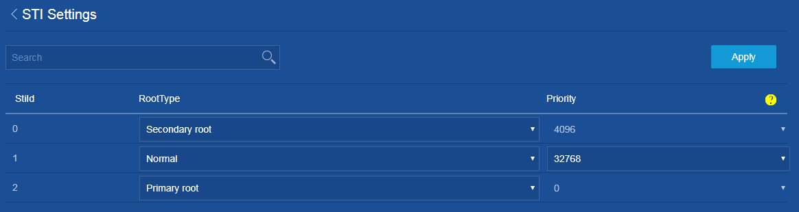
5. Configure Device B as the root bridge of MSTI 2 and a secondary root bridge of MSTI 0:
a. Click the ![]() icon
next to MSTI settings to access the STI Settings page.
icon
next to MSTI settings to access the STI Settings page.
b. Set the root type for MSTI 0 to Secondary root.
c. Set the root type for MSTI 2 to Primary root.
d. Click Apply.
The system displays a success message after it configures STI settings.
Figure 9 Configuring STI setting
6. Save the configuration:
Click the Save icon ![]() at the
upper left of the page.
at the
upper left of the page.
Configuring Device C
1. Create VLANs 11 through 30:
a. From the left navigation pane, select Network > Links > VLAN.
b. Click the Add icon ![]() to create
VLANs 11 through 30.
to create
VLANs 11 through 30.
c. Enter 11-30 in the VLAN list field.
d. Click Apply.
2. Configure GigabitEthernet 1/0/1, GigabitEthernet 1/0/2, and GigabitEthernet 1/0/3 as trunk VLANs 11 through 30:
a. From the left navigation pane, select Network > Interfaces > Interfaces.
b. Click the ![]() icon
next to GigabitEthernet 1/0/1.
icon
next to GigabitEthernet 1/0/1.
c. Set the link type to Trunk.
d. Enter 11-30 in the Permit VLAN List field.
e. Click Apply.
The system displays a success message after it configures VLAN parameters for the interfaces.
f. Configure GigabitEthernet 1/0/2 and GigabitEthernet 1/0/3 in the same way GigabitEthernet 1/0/1 is configured. (Details not shown.)
3. Enable STP:
a. From the left navigation pane, select Network > Links > STP.
b. Click Enable STP.
The default spanning tree mode is MSTP.
4. Configure the MST region name and VLAN-to-MSTI mapping:
a. Click the ![]() icon
next to MST region to access the MST Region Settings page.
icon
next to MST region to access the MST Region Settings page.
b. Configure the MST region name as Test.
c. Map VLANs 11 through 20 to MSTI 1.
d. Map VLANs 21 through 30 to MSTI 2, and set the MSTP revision level to 0.
e. Click the ![]() icon
next to MST Region Settings to return to the STP page.
icon
next to MST Region Settings to return to the STP page.
Figure 10 Configuring the MST region

5. Save the configuration:
Click the Save icon ![]() at the
upper left of the page.
at the
upper left of the page.
Configuring Device D
1. Create VLANs 11 through 30:
a. From the left navigation pane, select Network > Links > VLAN.
b. Click the Add icon ![]() to create
VLANs 11 through 30.
to create
VLANs 11 through 30.
c. Enter 11-30 in the VLAN list field.
d. Click Apply.
2. Configure GigabitEthernet 1/0/1, GigabitEthernet 1/0/2, and GigabitEthernet 1/0/3 as trunk VLANs 11 through 30:
a. From the left navigation pane, select Network > Interfaces > Interfaces.
b. Click the ![]() icon
next to GigabitEthernet 1/0/1.
icon
next to GigabitEthernet 1/0/1.
c. Set the link type to Trunk.
d. Enter 11-30 in the Permit VLAN List field.
e. Click Apply.
The system displays a success message after it configures VLAN parameters for the interfaces.
f. Configure GigabitEthernet 1/0/2 and GigabitEthernet 1/0/3 in the same way GigabitEthernet 1/0/1 is configured. (Details not shown.)
3. Enable STP:
a. From the left navigation pane, select Network > Links > STP.
b. Click Enable STP.
The default spanning tree mode is MSTP.
4. Configure the MST region name and VLAN-to-MSTI mapping:
a. Click the ![]() icon
next to MST region to access the MST Region Settings page.
icon
next to MST region to access the MST Region Settings page.
b. Configure the MST region name as Test.
c. Map VLANs 11 through 20 to MSTI 1.
d. Map VLANs 21 through 30 to MSTI 2, and set the MSTP revision level to 0.
e. Click the ![]() icon
next to MST Region Settings to return to the STP page.
icon
next to MST Region Settings to return to the STP page.
Figure 11 Configuring the MST region
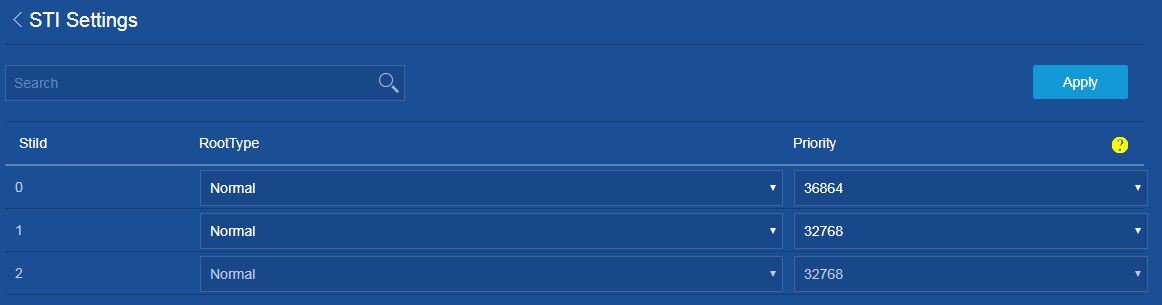
5. Set the device priority to 36864 in MSTI 0, which is lower than the default priority 32768 of Device C:
a. Click the ![]() icon
next to MSTI settings to access the STI Settings page.
icon
next to MSTI settings to access the STI Settings page.
b. Set the priority for MSTI 0 to 36864.
c. Click Apply.
The system displays a success message after it configures STI settings.
Figure 12 Configuring STI settings
6. Save the configuration:
Click the Save icon ![]() at the upper left of the page.
at the upper left of the page.
Verifying the configuration
1. On the Network > Links > STP > Port Instance State page, view the port role and STP state for each interface to verify that Layer 2 loops have been eliminated in each MSTI.
2. Verify that the network can accommodate topology changes:
a. Shut down GigabitEthernet 1/0/1 on Device C.
b. On the Network > Links > STP > Port Instance State page for Device C, verify that GigabitEthernet 1/0/2 becomes the uplink port for MSTI 0 and MSTI 1.