- Table of Contents
-
- H3C Campus Fixed-Port Switches Web-Based Quick Start Configuration Guide-6W100
- 01-Compatible Product Models
- 02-Configuring Web Login with the Default IP
- 03-Web Login to a Device Without a Default IP
- 04-Interface Settings
- 05-PoE
- 06-VLAN
- 07-DHCP Server
- 08-DHCP Relay Agent
- 09-Static Routing
- 10-Policy-Based Routing
- 11-Ethernet Link Aggregation
- 12-Port Mirroring
- 13-Packet Filtering
- 14-Interface Rate Limit
- 15-Traffic Constrain
- 16-Spanning Tree
- 17-Direct Portal Authentication
- 18-Port Security
- 19-Port Isolation
- 20-ARP Attack Protection
- 21-Configuring a Static ARP Entry
- 22-IGMP Snooping
- 23-Enabling IPSG on an Interface
- 24-Software Upgrade
- 25-Adding Administrator Accounts
- 26-Ping and Tracert
- 27-Password Change
- 28-System Time
- 29-System Log
- 30-Configuration Backup, Export, Restoration to Factory Default
- 31-Device Reboot
- 32-Small-Sized Campus Network Configuration Guide
- Related Documents
-
| Title | Size | Download |
|---|---|---|
| 12-Port Mirroring | 232.59 KB |
Contents
Local Port Mirroring Quick Start Configuration Guide
Quick Start Configuration Guide for Layer 2 Remote Port Mirroring in Egress Port Mode
Local Port Mirroring Quick Start Configuration Guide
Network configuration
The departments of a company use IP addresses on different subnets. The R&D department uses subnet 10.1.1.0/24, and the marketing department uses subnet 12.1.1.0/24. Configure local port mirroring, so that the data monitoring device can monitor the traffic from the R&D department and marketing department to Internet.
Figure 1 Network diagram
Restrictions and guidelines
· A local mirroring group takes effect only when you configure both source ports and the destination port for the group. When you configure the destination port, do not use a port of an existing mirroring group.
· A destination port can receive both mirrored packets copied from source ports and normally forwarded packets from other ports. Use a destination port only for port mirroring, so the data monitoring device receives and analyzes only the mirrored traffic.
Procedure
1. Configure IP addresses for interfaces. (Details not shown.)
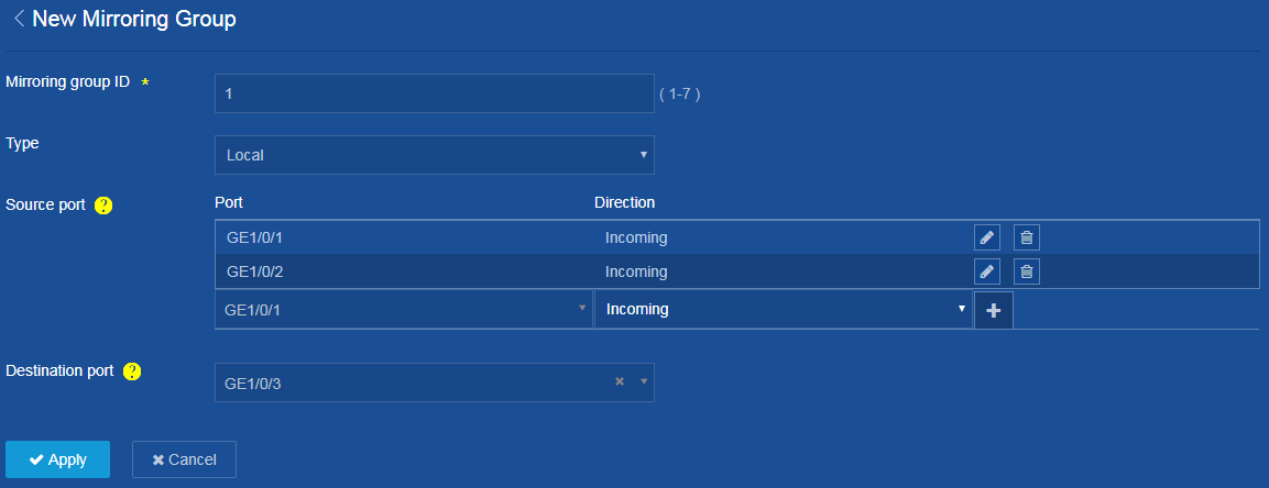
2. Configure local port mirroring:
a. From the left navigation pane, select Network > Mirroring > Port Mirroring.
The Port Mirroring page opens.
b. Click ![]() . The New Mirroring Group page opens.
. The New Mirroring Group page opens.
c. Configure the mirroring group ID as 1.
d. From the Type list, select Local.
e. Configure the interface that connects Device
A to the R&D department as a source port: Select port GE1/0/1, select the
incoming direction, and click ![]() to add the source port.
to add the source port.
f. Configure the interface that connects Device
A to the marketing department as a source port: Select port GE1/0/2, select the
incoming direction, and click ![]() to add the source port.
to add the source port.
g. Configure the port that connects Device A to the data monitoring device as the destination port: Select port GE1/0/3.
h. Click Apply.
The system displays a success message after it creates the local port mirroring group.
Figure 2 Configuring local port mirroring
3. Save the configuration.
Click the Save icon ![]() at
the upper left of the page.
at
the upper left of the page.
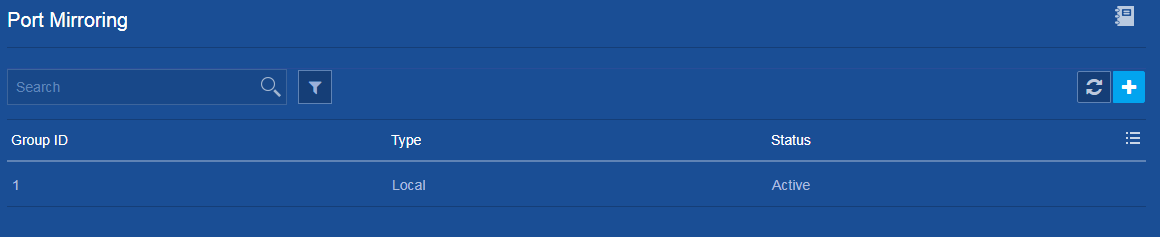
Verifying the configuration
On the Network > Mirroring > Port Mirroring page, view information about the configured local port mirroring group.
Figure 3 Local port mirroring
Quick Start Configuration Guide for Layer 2 Remote Port Mirroring in Egress Port Mode
Network configuration
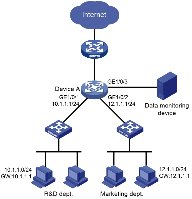
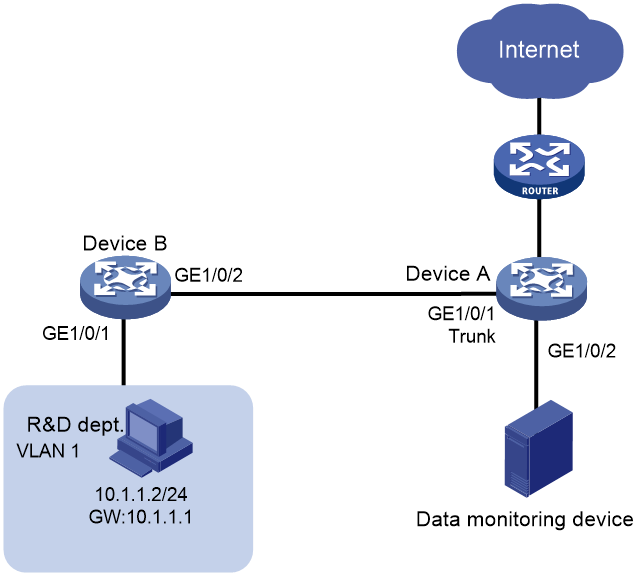
The R&D department of a company connects to the core device Device A through a Layer 2 network, and uses the subnet 10.1.1.0/24. Configure Layer 2 remote port mirroring in egress port mode, so that the data monitoring device can monitor the traffic from the R&D department.
Figure 4 Network diagram
Restrictions and guidelines
As a best practice to ensure mirrored packet forwarding, configure mirroring on devices in the order of destination device and source device.
When configuring remote port mirroring on the destination device and source device, follow these restrictions and guidelines:
· When configuring a remote probe VLAN, follow these restrictions and guidelines:
¡ Make sure the VLAN is an existing static VLAN.
¡ Use the VLAN for remote port mirroring only.
¡ The VLAN can be used by only one remote source group.
· Make sure the remote mirroring groups on the source device and destination device use the same remote probe VLAN.
When configuring remote port mirroring on the destination device, follow these restrictions and guidelines:
· Make sure the destination port is not the member port of any other mirroring group.
· Use the destination port for port mirroring only.
When configuring remote port mirroring on the source device, follow these restrictions and guidelines:
· For mirroring to operate correctly, do not assign source ports to the remote probe VLAN.
· For mirroring to operate properly, do not configure any of the following functions on the egress port:
¡ Spanning tree protocols.
¡ 802.1X.
¡ IGMP snooping.
¡ Static ARP.
¡ MAC address learning.
· Make sure the egress port is not the member port of an existing mirroring group.
Procedures
Configuring Device A (destination device)
1. Configure IP addresses for interfaces. (Details not shown.)
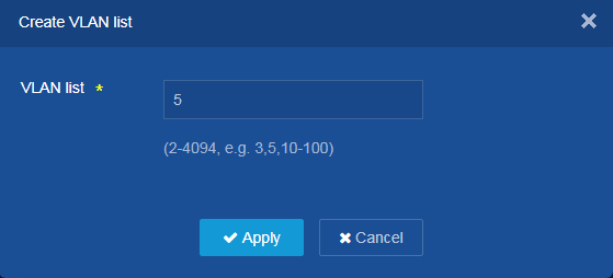
2. Create the remote probe VLAN:
a. From the left navigation pane, select Network > Links > VLAN.
The VLAN page opens.
b. On this page, click the Create icon ![]() to
create VLAN 5, which is to be used as the remote probe VLAN.
to
create VLAN 5, which is to be used as the remote probe VLAN.
Figure 5 Creating the remote probe VLAN
c. Add destination port GE 1/0/2 to the remote probe VLAN. (Details not shown.)
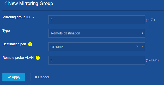
3. Configure a Layer 2 remote port mirroring group:
a. From the left navigation pane, select Network > Mirroring > Port Mirroring.
The Port Mirroring page opens.
b. Click ![]() . The New Mirroring Group page opens.
. The New Mirroring Group page opens.
c. Configure the mirroring group ID as 2.
d. Select Remote destination from the Type list.
e. Configure the port that connects Device B to the data monitoring device as the destination port: Select port GE1/0/2.
f. Set the remote probe VLAN to 5.
g. Click Apply.
The system displays a success message after it configures remote port mirroring on the destination device.
Figure 6 Configuring a Layer 2 remote port mirroring group
4. Save the configuration.
Click the Save icon ![]() at
the upper left of the page.
at
the upper left of the page.
Configure Device B (source device)
1. Configure IP addresses for interfaces. (Details not shown.)
2. Create the remote probe VLAN in the same way the remote probe VLAN is created on Device A.
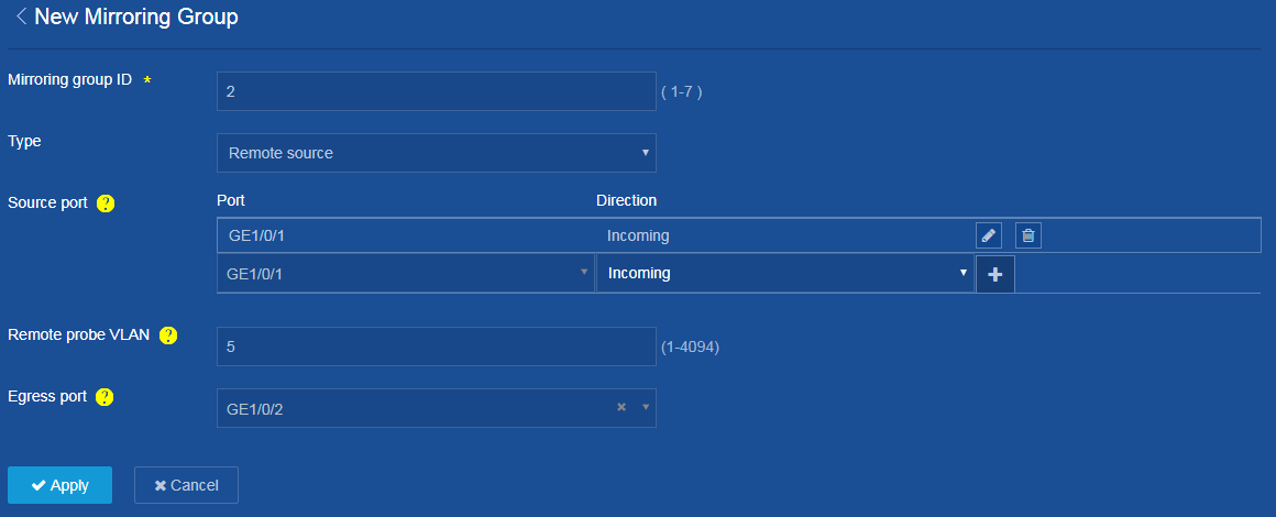
3. Configure a Layer 2 remote port mirroring group:
a. From the left navigation pane, select Network > Mirroring > Port Mirroring.
The Port Mirroring page opens.
b. Click ![]() . The New Mirroring Group page opens.
. The New Mirroring Group page opens.
c. Configure the mirroring group ID as 2.
d. Select Remote source from the Type list.
e. Configure the interface that connects Device
B to the R&D department as a source port: Select port GE1/0/1, select the
incoming direction, and click ![]() to add the source port.
to add the source port.
f. Set the remote probe VLAN to 5.
g. Configure the port that connects Device B to the destination device as the egress port: Select port GE1/0/2.
h. Click Apply.
The system displays a success message after it configures remote port mirroring on the source device.
Figure 7 Configuring a Layer 2 remote port mirroring group
4. Save the configuration.
Click the Save icon ![]() at
the upper left of the page.
at
the upper left of the page.
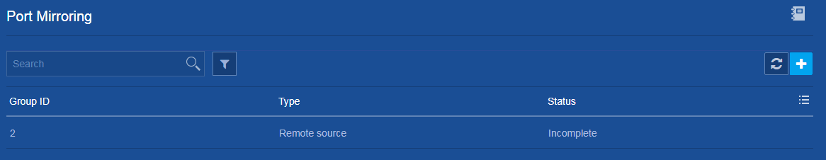
Verifying the configuration
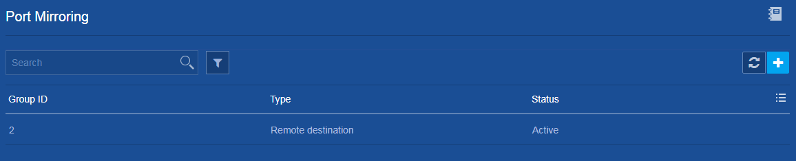
1. On the Network > Mirroring > Port Mirroring page for Device A, view information about the configured remote port mirroring group.
Figure 8 Remote destination group
2. On the Network > Mirroring > Port Mirroring page for Device B, view information about the configured remote port mirroring group.
Figure 9 Remote source group