- Table of Contents
-
- H3C Campus Fixed-Port Switches Web-Based Quick Start Configuration Guide-6W100
- 01-Compatible Product Models
- 02-Configuring Web Login with the Default IP
- 03-Web Login to a Device Without a Default IP
- 04-Interface Settings
- 05-PoE
- 06-VLAN
- 07-DHCP Server
- 08-DHCP Relay Agent
- 09-Static Routing
- 10-Policy-Based Routing
- 11-Ethernet Link Aggregation
- 12-Port Mirroring
- 13-Packet Filtering
- 14-Interface Rate Limit
- 15-Traffic Constrain
- 16-Spanning Tree
- 17-Direct Portal Authentication
- 18-Port Security
- 19-Port Isolation
- 20-ARP Attack Protection
- 21-Configuring a Static ARP Entry
- 22-IGMP Snooping
- 23-Enabling IPSG on an Interface
- 24-Software Upgrade
- 25-Adding Administrator Accounts
- 26-Ping and Tracert
- 27-Password Change
- 28-System Time
- 29-System Log
- 30-Configuration Backup, Export, Restoration to Factory Default
- 31-Device Reboot
- 32-Small-Sized Campus Network Configuration Guide
- Related Documents
-
| Title | Size | Download |
|---|---|---|
| 19-Port Isolation | 80.70 KB |
Port Isolation Quick Start Configuration Guide
Network configuration
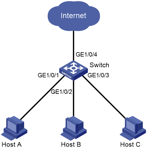
Community users Host A, Host B, and Host C are connected to GigabitEthernet 1/0/1, GigabitEthernet 1/0/2, and GigabitEthernet 1/0/3 of Switch, respectively. Switch is connected to Internet through GigabitEthernet 1/0/4. Configure port isolation to isolate Layer 2 packets among Host A, Host B, and Host C, and allow these hosts to communicate with Internet.
Figure 1 Network diagram
Procedure
1. Configure port isolation:
a. From the left navigation pane, select Network > Interfaces > Isolation.
The Isolation page opens.
b. On this page, perform the following tasks:
- Click the Create icon ![]() . The Create Isolation Group page opens.
. The Create Isolation Group page opens.
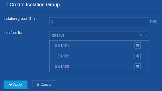
- Configure the isolation group ID as 2.
- Add GE1/0/1, GE1/0/2, and GE1/0/3 to the interface list.
- Click Apply.
The system displays a success message after it configures the isolation group.
Figure 2 Creating a port isolation group and adding member ports
2. Save the configuration.
Click the Save icon ![]() at
the upper left of the page.
at
the upper left of the page.
Verifying the configuration
1. Verify that GigabitEthernet 1/0/1, GigabitEthernet 1/0/2, and GigabitEthernet 1/0/3 of Switch are isolated at Layer 2.
2. Verify that Host A, Host B, and Host C cannot ping each other.