- Table of Contents
-
- H3C Campus Fixed-Port Switches Web-Based Quick Start Configuration Guide-6W100
- 01-Compatible Product Models
- 02-Configuring Web Login with the Default IP
- 03-Web Login to a Device Without a Default IP
- 04-Interface Settings
- 05-PoE
- 06-VLAN
- 07-DHCP Server
- 08-DHCP Relay Agent
- 09-Static Routing
- 10-Policy-Based Routing
- 11-Ethernet Link Aggregation
- 12-Port Mirroring
- 13-Packet Filtering
- 14-Interface Rate Limit
- 15-Traffic Constrain
- 16-Spanning Tree
- 17-Direct Portal Authentication
- 18-Port Security
- 19-Port Isolation
- 20-ARP Attack Protection
- 21-Configuring a Static ARP Entry
- 22-IGMP Snooping
- 23-Enabling IPSG on an Interface
- 24-Software Upgrade
- 25-Adding Administrator Accounts
- 26-Ping and Tracert
- 27-Password Change
- 28-System Time
- 29-System Log
- 30-Configuration Backup, Export, Restoration to Factory Default
- 31-Device Reboot
- 32-Small-Sized Campus Network Configuration Guide
- Related Documents
-
| Title | Size | Download |
|---|---|---|
| 20-ARP Attack Protection | 465.47 KB |
Contents
Unresolvable IP Attack Protection Quick Start Configuration Guide
ARP Attack Detection Quick Start Configuration Guide
Unresolvable IP Attack Protection Quick Start Configuration Guide
Network configuration
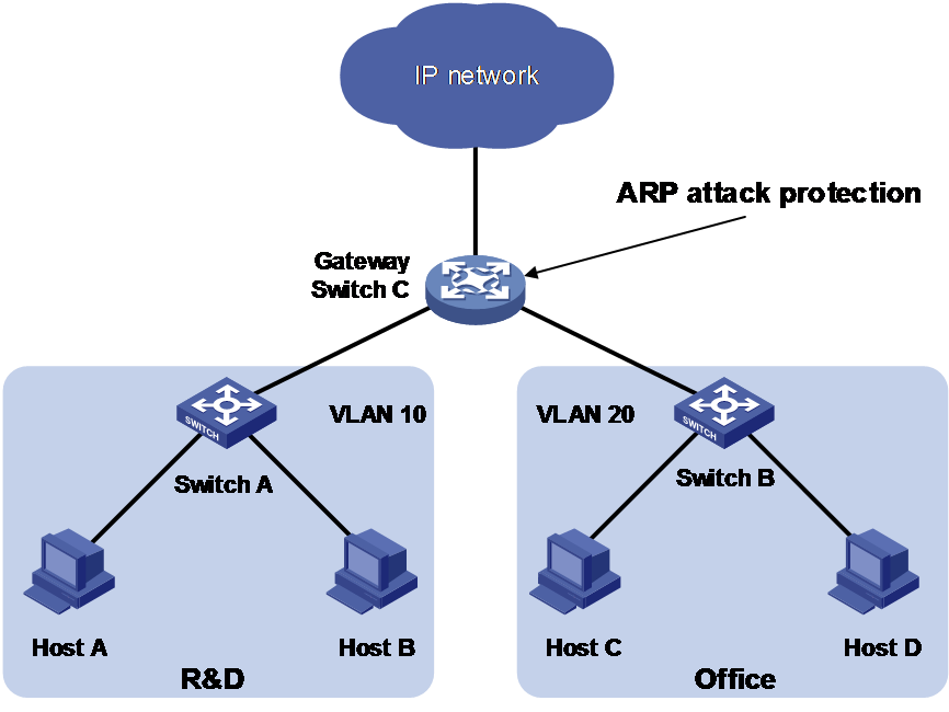
As shown in Figure 1, a LAN contains two areas: an R&D area in VLAN 10 and an office area in VLAN 20. Each area connects to the gateway (Switch C) through an access switch.
A large number of ARP requests are detected in the office area and are considered an attack caused by unresolvable IP packets. To prevent the attack, configure ARP source suppression or ARP blackhole routing.
Analysis
· If the attack packets have different source addresses, configure ARP blackhole routing.
· If the attack packets have the same source address, configure ARP source suppression and set the maximum number of unresolvable packets that can be processed per source IP address within 5 seconds. If unresolvable packets received from the IP address within 5 seconds exceed the limit, the gateway stops ARP resolution for the packets from that IP address until the 5 seconds elapse.
Procedures
1. Enable ARP blackhole routing:
a. Log in to the Web configuration interface for Switch C. From the left navigation pane, select Network > IP > ARP.
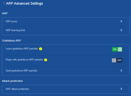
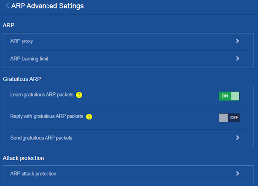
b. Click the ![]() icon in the right. On the ARP Advanced Settings page that
opens, click ARP attack protection.
icon in the right. On the ARP Advanced Settings page that
opens, click ARP attack protection.
Figure 2 Entering the ARP attack protection page
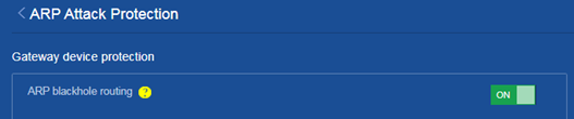
c. On the ARP attack protection page that opens, turn on the ARP blackhole routing feature.
Figure 3 Enabling the ARP blackhole routing feature
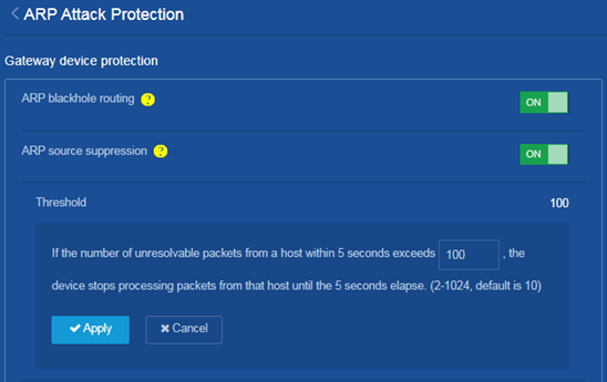
2. Configure ARP source suppression:
On the ARP attack protection page, turn on the ARP source suppression feature and set the threshold to 100.
Figure 4 Enabling the ARP source suppression feature and setting the threshold
3. Save the configuration:
Click the Save icon ![]() at the upper left of the page.
at the upper left of the page.
Verifying the configuration
Verify the following:
· When the unresolvable packets received from an IP address within 5 seconds exceed the limit, Switch C stops ARP resolution processing for the packets from that IP address until the 5 seconds elapse.
· When the unresolvable packets have different source addresses, Switch C creates a blackhole route destined for each unresolved IP address and discards the packets.
ARP Attack Detection Quick Start Configuration Guide
Network configuration
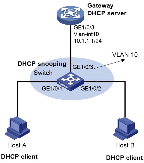
As shown in Figure 5, configure Switch to perform user validity check and ARP packet validity check based on DHCP snooping entries for connected hosts.
Procedures
1. Configure Gateway (DHCP server), and Host A and Host B (DHCP clients). (Details not shown.)
2. Configure DHCP snooping for Switch:
a. Access the Web configuration interface for Switch. From the left navigation pane, select Network > Links > DHCP Snooping.
b. On the DHCP Snooping page that opens, perform the following tasks:
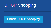
- Click Enable DHCP Snooping.
Figure 6 Enabling DHCP snooping
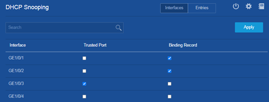
- Select Trusted Port for GigabitEthernet 1/0/3.
- Select Binding Record for GigabitEthernet 1/0/1 and GigabitEthernet 1/0/2 to enable recording of client information in DHCP snooping entries on the two interfaces.
- Click Apply.
Figure 7 Configuring the trusted interface and enabling recording of client information in DHCP snooping entries
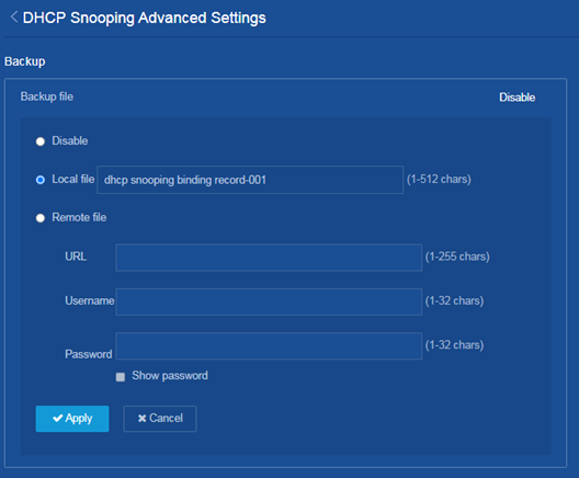
c. On the DHCP Snooping
page, click the ![]() icon at the upper
right. On the DHCP Snooping
Advanced Settings page that opens, configure the
backup file. Select Local file and name the file as dhcp
snooping binding record-001.
icon at the upper
right. On the DHCP Snooping
Advanced Settings page that opens, configure the
backup file. Select Local file and name the file as dhcp
snooping binding record-001.
Figure 8 Saving the backup file locally
3. Enable ARP attack detection on Switch.
a. Access the configuration interface for Switch. From the left navigation pane, select Network > IP > ARP.
b. Click the ![]() icon at the upper right of the page. On the ARP Advanced
Settings page that opens, click ARP attack protection.
icon at the upper right of the page. On the ARP Advanced
Settings page that opens, click ARP attack protection.
Figure 9 Entering the ARP attack protection page
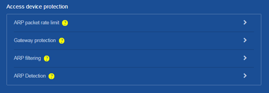
c. On the ARP attack protection page that opens, select Access device protection > ARP Detection.
Figure 10 Entering the ARP Detection page
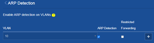
d. On the ARP Detection page, select ARP Detection for the VLAN, and then
click the Add icon ![]() .
.
Figure 11 Enabling ARP detection in the VLAN
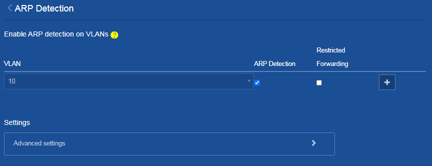
e. On the ARP Detection page, click Advanced settings.
Figure 12 Entering the ARP Detection Advanced Settings page
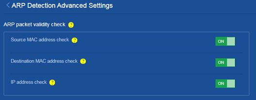
f. On the ARP Detection Advanced Settings page, perform the following tasks:
- Click ON for Source MAC address check, Destination MAC address check and IP address check to enable the services.
Figure 13 Configuring ARP packet validity check
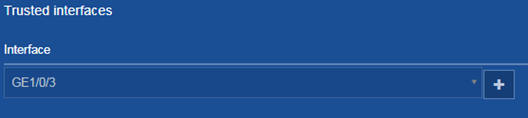
- Configure GigabitEthernet1/0/3 as a trusted
interface, and then click the Add icon ![]() .
.
Figure 14 Configuring the trusted interface
4. Save the configuration:
Click the Save icon ![]() at the upper left of the page.
at the upper left of the page.
Verifying the configuration
Verify that Switch first checks the validity of ARP packets received on GigabitEthernet 1/0/1 and GigabitEthernet 1/0/2. If the ARP packets are confirmed valid, Switch performs user validity check by using the DHCP snooping entries.