- Table of Contents
-
- H3C S12500R Ethernet Switch Router Series Config Examples-6W101
- 01-Login Management Configuration Examples
- 02-RBAC Configuration Examples
- 03-Software Upgrade Examples
- 04-Ethernet Link Aggregation Configuration Examples
- 05-Port Isolation Configuration Examples
- 06-Spanning Tree Configuration Examples
- 07-VLAN Configuration Examples
- 08-VLAN Tagging Configuration Examples
- 09-DHCP Snooping Configuration Examples
- 10-Cross-Subnet Dynamic IP Address Allocation Configuration Examples
- 11-IPv6 over IPv4 Tunneling with OSPFv3 Configuration Examples
- 12-GRE Tunnel Configuration Examples
- 13-GRE with OSPF Configuration Examples
- 14-OSPF Configuration Examples
- 15-IS-IS Configuration Examples
- 16-BGP Configuration Examples
- 17-Policy-Based Routing Configuration Examples
- 18-OSPFv3 Configuration Examples
- 19-IPv6 IS-IS Configuration Examples
- 20-Routing Policy Configuration Examples
- 21-IGMP Snooping Configuration Examples
- 22-IGMP Configuration Examples
- 23-MLD Snooping Configuration Examples
- 24-Basic MPLS Configuration Examples
- 25-MPLS L3VPN Configuration Examples
- 26-ACL Configuration Examples
- 27-Control Plane-Based QoS Policy Configuration Examples
- 28-Traffic Policing Configuration Examples
- 29-GTS and Rate Limiting Configuration Examples
- 30-Priority Mapping and Queue Scheduling Configuration Examples
- 31-Traffic Filtering Configuration Examples
- 32-AAA Configuration Examples
- 33-SSH Configuration Examples
- 34-IP Source Guard Configuration Examples
- 35-Ethernet OAM Configuration Examples
- 36-CFD Configuration Examples
- 37-DLDP Configuration Examples
- 38-VRRP Configuration Examples
- 39-BFD Configuration Examples
- 40-NTP Configuration Examples
- 41-SNMP Configuration Examples
- 42-NQA Configuration Examples
- 43-Mirroring Configuration Examples
- 44-sFlow Configuration Examples
- 45-OpenFlow Configuration Examples
- 46-MAC Address Table Configuration Examples
- 47-Static Multicast MAC Address Entry Configuration Examples
- 48-IP Unnumbered Configuration Examples
- 49-Congestion Avoidance and Queue Scheduling Configuration Examples
- 50-Attack Protection Configuration Examples
- 51-Smart Link Configuration Examples
- 52-RRPP Configuration Examples
- 53-BGP Route Selection Configuration Examples
- 54-IS-IS Route Summarization Configuration Examples
- 55-MPLS OAM Configuration Examples
- 56-MPLS TE Configuration Examples
- 57-VXLAN Configuration Examples
- 58-NetStream Configuration Examples
- 59-EVPN-DCI over an MPLS L3VPN Network Configuration Examples
- 60-PTP Configuration Examples
- 61-S-MLAG Configuration Examples
- 62-MPLS SR Configuration Examples
- 63-Puppet Configuration Examples
- 64-Configuration Example of Using Ethernet OAM to Monitor ERPS Ring Link Performance
- 65-GRE Tunneling Between DHCP Relay and DHCP Server Configuration Examples
- 66-Loop Detection Configuration Examples
- 67-MPLS L3VPN+VRRP Configuration Examples
- 68-MSTP and VRRP Load Balancing Configuration Examples
- 69-Routing Policy for VPN Access Control Configuration Examples
- 70-Switch and Firewall Connection Configuration Examples for External Network Access
- 71-Switch and Router Connection Configuration Examples for External Network Access
- 72-VRRP Network Multicast Data Transmission Configuration Examples
- Related Documents
-
| Title | Size | Download |
|---|---|---|
| 72-VRRP Network Multicast Data Transmission Configuration Examples | 176.32 KB |
|
|
|
H3C S12500R Switch Router Series |
|
VRRP Network Multicast Data Transmission Configuration Examples |
|
|
Copyright © 2024 New H3C Technologies Co., Ltd. All rights reserved.
No part of this manual may be reproduced or transmitted in any form or by any means without prior written consent of New H3C Technologies Co., Ltd.
Except for the trademarks of New H3C Technologies Co., Ltd., any trademarks that may be mentioned in this document are the property of their respective owners.
The information in this document is subject to change without notice.
Example: Configuring multicast data transmission in a VRRP network
Configuring VLANs, VLAN interfaces, and loopback interfaces
Configuring link aggregation used for VRRP link backup
Configuring multicast protocols
Introduction
The following information provides an example for configuring multicast data transmission in a Virtual Router Redundancy Protocol (VRRP) network.
Prerequisites
Procedures and information in the examples might be slightly different depending on the software or hardware version of the products.
The configuration examples were created and verified in a lab environment, and all the devices were started with the factory default configuration. When you are working on a live network, make sure you understand the potential impact of every command on your network.
The following information is provided based on the assumption that you have basic knowledge of VRRP, Open Shortest Path First (OSPF), and multicast.
Example: Configuring multicast data transmission in a VRRP network
Network configuration
The campus network contains the egress gateways (Device A and Device B) and the core devices (Device C and Device D). The multicast source is deployed in the external network of the campus. The configuration requirements are as follows:
· Horizontal redundancy: Implement redundancy for critical nodes in the network (Device A, Device B, Device C, and Device D) to enhance network reliability.
· Vertical redundancy: Establish full-mesh connections between the egress gateways (Device A and Device B) and the core devices (Device C and Device D) to achieve link redundancy and backup.
· Configure the border gateways and core devices to ensure correct and reliable transmission of multicast data to downstream networks.
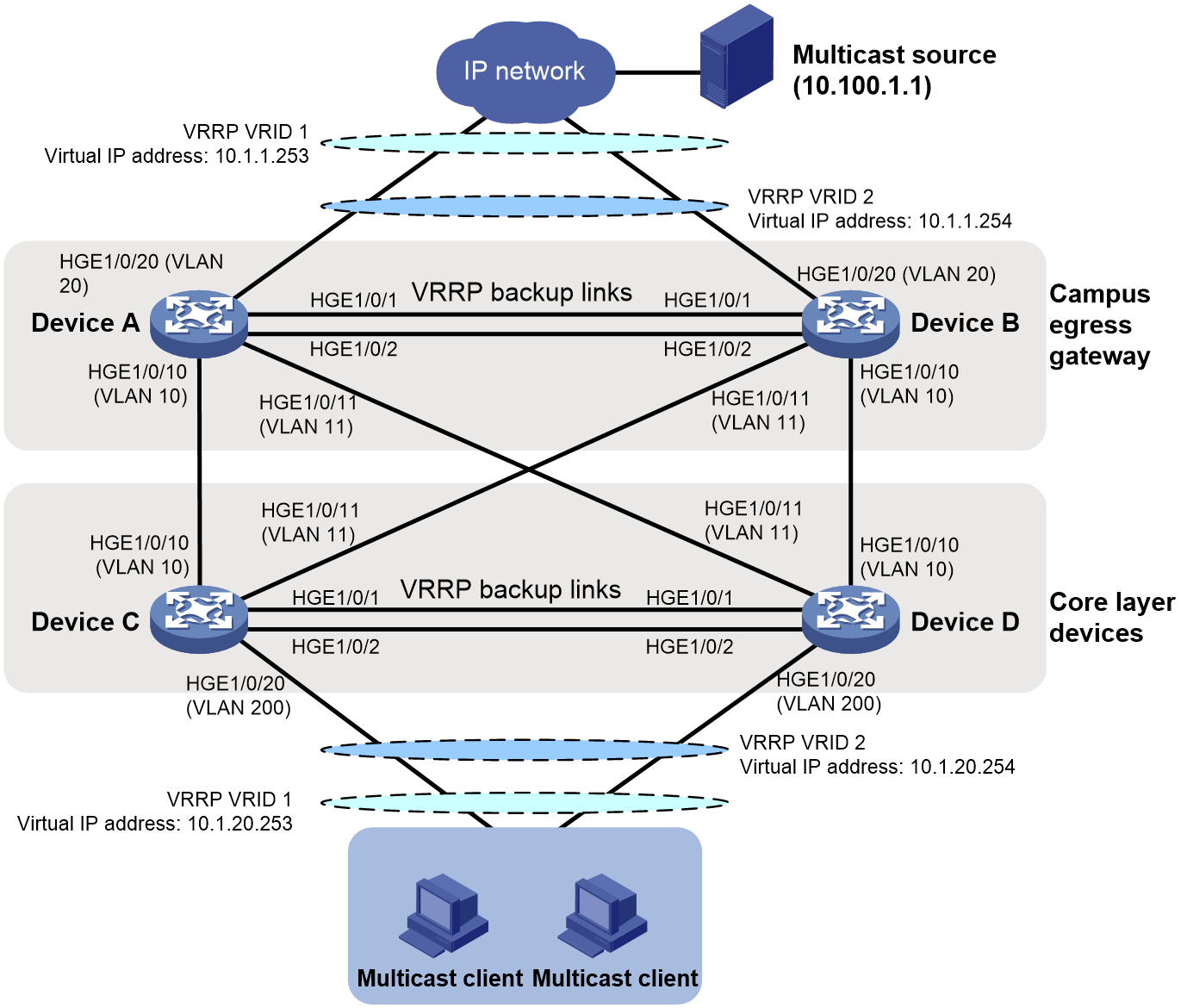
Table 1 shows the data plan in this example.
|
Device |
Interfaces |
VLAN |
IP addresses of the loopback interfaces/VLAN interfaces |
|
Device A |
Loop0 |
N/A |
1.1.1.1/32 |
|
HGE1/0/1, HGE1/0/2 |
VLAN 20 |
Layer 2 interfaces used for transmitting VRRP packets. |
|
|
HGE1/0/10 |
VLAN 10 |
10.1.10.1/24 |
|
|
HGE1/0/11 |
VLAN 11 |
10.1.11.1/24 |
|
|
HGE1/0/20 |
VLAN 20 |
10.1.1.20/24 |
|
|
Device B |
Loop0 |
N/A |
2.2.2.2/32 |
|
HGE1/0/20 |
VLAN 20 |
10.1.1.21/24 |
|
|
HGE1/0/1, HGE1/0/2 |
VLAN 20 |
Layer 2 interfaces used for transmitting VRRP packets. |
|
|
HGE1/0/10 |
VLAN 10 |
10.1.10.2/24 |
|
|
HGE1/0/11 |
VLAN 11 |
10.1.11.2/24 |
|
|
HGE1/0/20 |
VLAN 20 |
10.1.1.21/24 |
|
|
Device C |
Loop0 |
N/A |
3.3.3.3/32 |
|
HGE1/0/20 |
VLAN 200 |
10.1.20.20/24 |
|
|
HGE1/0/1, HGE1/0/2 |
VLAN 200 |
Layer 2 interfaces used for transmitting VRRP packets. |
|
|
HGE1/0/10 |
VLAN 10 |
10.1.10.3/24 |
|
|
HGE1/0/11 |
VLAN 11 |
10.1.11.3/24 |
|
|
Device D |
Loop0 |
N/A |
4.4.4.4/32 |
|
HGE1/0/20 |
VLAN 200 |
10.1.20.21/24 |
|
|
HGE1/0/1, HGE1/0/2 |
VLAN 200 |
Layer 2 interfaces used for transmitting VRRP packets. |
|
|
HGE1/0/10 |
VLAN 10 |
10.1.10.4/24 |
|
|
HGE1/0/11 |
VLAN 11 |
10.1.11.4/24 |
Analysis
1. Create VLANs on the devices and add the corresponding interfaces to the VLANs appropriately. Create a VLAN interface for each VLAN, and configure an IP address for the VLAN interface to ensure reachability of the local network.
2. Configure OSPF on the devices to that they can communicate with one another at Layer 3. Implement load balancing for unicast traffic between the egress gateways and core devices, reducing the pressure on a single link that forwards both unicast and multicast data.
3. Configure link aggregation for the links between Device A and Device B and between Device C and Device D to be used as backup links to transmit VRRP packets, improving VRRP network reliability.
4. Create two VRRP groups on Device A and Device B to implement redundancy and backup between the devices. Create two VRRP groups on Device C and Device D to implement redundancy and backup between the devices.
5. Configure multicast protocols on the devices to ensure correct forwarding of multicast data. Commonly used multicast protocols include Protocol Independent Multicast (PIM) and Internet Group Management Protocol (IGMP).
6. Configure BFD for OSPF and BFD for PIM on each device to ensure fast link fault detection and implement fast convergence of unicast and multicast routes.
Software versions used
This configuration example was created and verified on Release 5210 or later versions of S12500R.
Restrictions and guidelines
In this configuration example, some physical interfaces are required to operate in Layer 2 mode. To change the link mode of a physical interface to Layer 2, execute the port link-mode bridge command.
By default, interfaces on the device are disabled (in ADM or Administratively Down state). To have an interface operate, you must use the undo shutdown command to enable that interface.
To ensure correct network operation in a ring topology, perform the following operations:
· Make sure STP is disabled for interconnected interfaces. STP might block a port in the ring network, which can interrupt other Layer 3 services. By default, STP is enabled on Layer 2 interfaces. You need to manually disable it.
· Remove interconnected interfaces from VLAN 1 to prevent generating loops.
Procedures
Configuring VLANs, VLAN interfaces, and loopback interfaces
Configuring Device A
# Set the name of the device to Device A to facilitate management.
<Sysname> system-view
[Sysname] sysname DeviceA
# Create VLANs 10, 11, and 20.
[DeviceA] vlan 10 11 20
# Configure HGE 1/0/10, HGE 1/0/11, and HGE 1/0/20 as trunk ports, and assign them to VLAN 10, VLAN 11, and VLAN 20, respectively. (The default link type of an interface is access, and the interface is assigned to only VLAN 1.)
[DeviceA] interface hundredgige 1/0/10
[DeviceA-HundredGigE1/0/10] port link-type trunk
[DeviceA-HundredGigE1/0/10] port trunk permit vlan 10
[DeviceA-HundredGigE1/0/10] quit
[DeviceA] interface hundredgige 1/0/11
[DeviceA-HundredGigE1/0/11] port link-type trunk
[DeviceA-HundredGigE1/0/11] port trunk permit vlan 11
[DeviceA-HundredGigE1/0/11] quit
[DeviceA] interface hundredgige 1/0/20
[DeviceA-HundredGigE1/0/20] port link-type trunk
[DeviceA-HundredGigE1/0/20] port trunk permit vlan 20
[DeviceA-HundredGigE1/0/20] quit
# Create VLAN-interface 10 and configure its IP address as 10.1.10.1/24. Configure the IP address for VLAN-interface 11 as 10.1.11.1/24, and the IP address for VLAN-interface 20 as 10.1.1.20/24.
[DeviceA] interface vlan-interface 10
[DeviceA-Vlan-interface10] ip address 10.1.10.1 24
[DeviceA-Vlan-interface10] quit
[DeviceA] interface vlan-interface 11
[DeviceA-Vlan-interface11] ip address 10.1.11.1 24
[DeviceA-Vlan-interface11] quit
[DeviceA] interface vlan-interface 20
[DeviceA-Vlan-interface20] ip address 10.1.1.20 24
[DeviceA-Vlan-interface20] quit
# Create loopback interface 0 and configure its IP address as 1.1.1.1/32.
[DeviceA] interface loopback 0
[DeviceA-LoopBack0] ip address 1.1.1.1 32
[DeviceA-LoopBack0] quit
Configuring Device B
Configure the following settings on Device B in the same way Device A is configured. (Details not shown.)
· Create loopback interface 0 and configure its IP address as 2.2.2.2/32.
· Create VLAN 10, and configure the IP address for VLAN-interface 10 as 10.1.10.2/24.
· Create VLAN 11, and configure the IP address for VLAN-interface 11 as 10.1.11.2/24.
· Create VLAN 20, and configure the IP address for VLAN-interface 20 as 10.1.1.21/24.
Configuring Device C
Configure the following settings on Device C in the same way Device A is configured. (Details not shown.)
· Create loopback interface 0 and configure its IP address as 3.3.3.3/32.
· Create VLAN 10, and configure the IP address for VLAN-interface 10 as 10.1.10.3/24.
· Create VLAN 11, and configure the IP address for VLAN-interface 11 as 10.1.11.3/24.
· Create VLAN 20, and configure the IP address for VLAN-interface 20 as 10.1.20.20/24.
Configuring Device D
Configure the following settings on Device D in the same way Device A is configured. (Details not shown.)
· Create loopback interface 0 and configure its IP address as 4.4.4.4/32.
· Create VLAN 10, and configure the IP address for VLAN-interface 10 as 10.1.10.4/24.
· Create VLAN 11, and configure the IP address for VLAN-interface 11 as 10.1.11.4/24.
· Create VLAN 20, and configure the IP address for VLAN-interface 20 as 10.1.20.21/24.
Configuring OSPF
Configuring Device A
# Enable OSPF, add Device A to Area 0, and advertise the loopback interface IP address and network routes of interfaces within Area 0.
[DeviceA] ospf
[DeviceA-ospf-1] area 0
[DeviceA-ospf-1-area-0.0.0.0] network 1.1.1.1 0.0.0.0
[DeviceA-ospf-1-area-0.0.0.0] network 10.1.1.0 0.0.0.255
[DeviceA-ospf-1-area-0.0.0.0] network 10.1.10.0 0.0.0.255
[DeviceA-ospf-1-area-0.0.0.0] network 10.1.11.0 0.0.0.255
[DeviceA-ospf-1-area-0.0.0.0] quit
[DeviceA-ospf-1] quit
Configuring Device B, Device C, and Device D
Configure Device B, Device C, and Device D in the same way Device A is configured. For more information, see Table 1. (Details not shown.)
Configuring link aggregation used for VRRP link backup
Configuring Device A
# Create Layer 2 aggregate interface Bridge-Aggregation 1 and set its aggregation mode to dynamic.
[DeviceA] interface bridge-aggregation 1
[DeviceA-Bridge-Aggregation1] link-aggregation mode dynamic
[DeviceA-Bridge-Aggregation1] quit
# Assign interfaces HundredGigE 1/0/1 and HundredGigE 1/0/2 to link aggregation group 1.
[DeviceA] interface hundredgige 1/0/1
[DeviceA-HundredGigE1/0/1] port link-aggregation group 1
[DeviceA-HundredGigE1/0/1] quit
[DeviceA] interface hundredgige 1/0/2
[DeviceA-HundredGigE1/0/2] port link-aggregation group 1
[DeviceA-HundredGigE1/0/2] quit
# Configure Layer 2 aggregate interface Bridge-Aggregation 1 as a trunk port and assign it to VLAN 20 for transmitting VRRP packets.
[DeviceA] interface bridge-aggregation 1
[DeviceA-Bridge-Aggregation1] port link-type trunk
[DeviceA-Bridge-Aggregation1] port trunk permit vlan 20
Configuring Device B, Device C, and Device D
Configure Device B, Device C, and Device D in the same way Device A is configured. For more information, see Table 1. (Details not shown.)
Configuring VRRP groups
Configuring VRRP group 1
1. Configure Device A:
# Create VRRP group 1, assign priority 120 to Device A (for Device A to become the master), and set the preemption delay to 20 seconds. (The default priority is 100, and the device with the highest priority becomes the master. The preemption delay applies to only the master and the default value is 0 seconds. Set the preemption delay to 20 seconds to avoid frequent status switchover due to network instability.)
[DeviceA] interface vlan-interface 20
[DeviceA-Vlan-interface20] vrrp vrid 1 virtual-ip 10.1.1.253
[DeviceA-Vlan-interface20] vrrp vrid 1 priority 120
[DeviceA-Vlan-interface20] vrrp vrid 1 preempt-mode delay 20
[DeviceA-Vlan-interface20] quit
2. Configure Device B:
# Create VRRP group 1, and assign the default priority to Device B (for Device B to become the backup).
<DeviceB> system-view
[DeviceB] interface vlan-interface 20
[DeviceB-Vlan-interface20] vrrp vrid 1 virtual-ip 10.1.1.253
[DeviceB-Vlan-interface20] quit
3. Configure Device C:
# Create VRRP group 1, assign priority 120 to Device C (for Device C to become the master), and set the preemption delay to 20 seconds. (The default priority is 100, and the device with the highest priority becomes the master. The preemption delay applies to only the master and the default value is 0 seconds. Set the preemption delay to 20 seconds to avoid frequent status switchover due to network instability.)
<DeviceC> system-view
[DeviceC] interface vlan-interface 200
[DeviceC-Vlan-interface200] vrrp vrid 1 virtual-ip 10.1.20.253
[DeviceC-Vlan-interface200] vrrp vrid 1 priority 120
[DeviceC-Vlan-interface200] vrrp vrid 1 preempt-mode delay 20
[DeviceC-Vlan-interface200] quit
4. Configure Device D:
# Create VRRP group 1, and assign the default priority to Device D (for Device D to become the backup).
<DeviceD> system-view
[DeviceD] interface vlan-interface 200
[DeviceD-Vlan-interface200] vrrp vrid 1 virtual-ip 10.1.20.253
[DeviceD-Vlan-interface200] quit
Configuring VRRP group 2
1. Configure Device A:
# Create VRRP group 2, and assign the default priority to Device A (for Device A to become the backup).
[DeviceA] interface vlan-interface 20
[DeviceA-Vlan-interface20] vrrp vrid 2 virtual-ip 10.1.1.254
[DeviceA-Vlan-interface20] quit
2. Configure Device B:
# Create VRRP group 2, assign priority 120 to Device B (for Device B to become the master), and set the preemption delay to 20 seconds.
[DeviceB] interface vlan-interface 20
[DeviceB-Vlan-interface20] vrrp vrid 2 virtual-ip 10.1.1.254
[DeviceB-Vlan-interface20] vrrp vrid 2 priority 120
[DeviceB-Vlan-interface20] vrrp vrid 2 preempt-mode delay 20
[DeviceB-Vlan-interface20] quit
3. Configure Device C:
# Create VRRP group 2, and assign the default priority to Device C (for Device C to become the backup).
[DeviceC] interface vlan-interface 200
[DeviceC-Vlan-interface200] vrrp vrid 2 virtual-ip 10.1.20.254
[DeviceC-Vlan-interface200] quit
4. Configure Device D:
# Create VRRP group 2, assign priority 120 to Device D (for Device D to become the master), and set the preemption delay to 20 seconds.
[DeviceD] interface vlan-interface 200
[DeviceD-Vlan-interface200] vrrp vrid 2 virtual-ip 10.1.20.254
[DeviceD-Vlan-interface200] vrrp vrid 2 priority 120
[DeviceD-Vlan-interface200] vrrp vrid 2 preempt-mode delay 20
[DeviceD-Vlan-interface200] quit
Configuring multicast protocols
Configuring Device A
# Enable IP multicast routing, and enable PIM-SM on the interfaces.
[DeviceA] multicast routing
[DeviceA-mrib] quit
[DeviceA] interface loopback 0
[DeviceA-LoopBack0] pim sm
[DeviceA-LoopBack0] quit
[DeviceA] interface vlan-interface 10
[DeviceA-Vlan-interface10] pim sm
[DeviceA-Vlan-interface10] quit
[DeviceA] interface vlan-interface 11
[DeviceA-Vlan-interface11] pim sm
[DeviceA-Vlan-interface11] quit
[DeviceA] interface vlan-interface 20
[DeviceA-Vlan-interface20] pim sm
[DeviceA-Vlan-interface20] quit
Configuring Device B
Configure Device B in the same way Device A is configured. (Details not shown.)
Configuring Device C
# Enable IP multicast routing, enable PIM-SM on the interfaces, and enable IGMP on the access interface.
[DeviceC] multicast routing
[DeviceC-mrib] quit
[DeviceC] interface loopback 0
[DeviceC-LoopBack0] pim sm
[DeviceC-LoopBack0] quit
[DeviceC] interface vlan-interface 10
[DeviceC-Vlan-interface10] pim sm
[DeviceC-Vlan-interface10] quit
[DeviceC] interface vlan-interface 11
[DeviceC-Vlan-interface11] pim sm
[DeviceC-Vlan-interface11] quit
[DeviceC] interface vlan-interface 200
[DeviceC-Vlan-interface200] pim sm
[DeviceC-Vlan-interface200] igmp enable
[DeviceC-Vlan-interface200] quit
# Configure Device as a dynamic RP.
[DeviceC] pim
[DeviceC-pim] c-bsr 3.3.3.3
[DeviceC-pim] c-rp 3.3.3.3
[DeviceC-pim] quit
Configuring Device D
Configure Device D in the same way Device C is configured. (Details not shown.)
Configuring BFD
Configuring Device A
# Enable BFD, configure BFD for OSPF, and configure BFD for PIM.
[DeviceA] bfd session init-mode active
[DeviceA] interface vlan-interface 10
[DeviceA-Vlan-interface10] ospf bfd enable
[DeviceA-Vlan-interface10] pim bfd enable
[DeviceA-Vlan-interface10] quit
[DeviceA] interface vlan-interface 11
[DeviceA-Vlan-interface11] ospf bfd enable
[DeviceA-Vlan-interface11] pim bfd enable
[DeviceA-Vlan-interface11] quit
[DeviceA] interface vlan-interface 20
[DeviceA-Vlan-interface20] ospf bfd enable
[DeviceA-Vlan-interface20] pim bfd enable
[DeviceA-Vlan-interface20] quit
Configuring Device B, Device C, and Device D
Configure Device B, Device C, and Device D in the same way Device A is configured. For more information, see Table 1. (Details not shown.)
Verifying the configuration
Verifying the link aggregation configuration
Verify that Layer 2 aggregate interface 1 on Device A, Device B, Device C, and Device D has two member ports: HundredGigE 1/0/1 and HundredGigE 1/0/2. Both ports are in Selected state.
Output example on Device A:
[DeviceA] display link-aggregation verbose Bridge-Aggregation 1
Loadsharing Type: Shar -- Loadsharing, NonS -- Non-Loadsharing
Port Status: S -- Selected, U -- Unselected, I -- Individual
Port: A -- Auto port, M -- Management port, R -- Reference port
Flags: A -- LACP_Activity, B -- LACP_Timeout, C -- Aggregation,
D -- Synchronization, E -- Collecting, F -- Distributing,
G -- Defaulted, H -- Expired
Aggregate Interface: Bridge-Aggregation1
Creation Mode: Manual
Aggregation Mode: Dynamic
Loadsharing Type: Shar
Management VLANs: None
System ID: 0x8000, 2a53-1c67-0100
Local:
Port Status Priority Index Oper-Key Flag
HGE1/0/1(R) S 32768 1 1 {ACDEF}
HGE1/0/2 S 32768 2 1 {ACDEF}
Remote:
Actor Priority Index Oper-Key SystemID Flag
HGE1/0/1 32768 1 1 0x8000, 2a58-58b6-0200 {ACDEF}
HGE1/0/2 32768 2 1 0x8000, 2a58-58b6-0200 {ACDEF}
Verifying the VRRP configuration
Verify that the following information exist:
· Device A operates as the master in VRRP group 1. Device B operates as the backup in VRRP group 1.
· Device A operates as the backup in VRRP group 2. Device B operates as the master in VRRP group 2.
· Device C operates as the master in VRRP group 1. Device D operates as the backup in VRRP group 1.
· Device C operates as the backup in VRRP group 2. Device D operates as the master in VRRP group 2.
Output example on Device A:
[DeviceA] display vrrp
IPv4 Virtual Router Information:
Running mode : Standard
Total number of virtual routers : 2
Interface VRID State Running Adver Auth Virtual
Pri Timer Type IP
----------------------------------------------------------------------------
Vlan20 1 Master 120 100 Not supported 10.1.1.253
Vlan20 2 Backup 100 100 Not supported 10.1.1.254
Output example on Device B:
[DeviceB] display vrrp
IPv4 Virtual Router Information:
Running mode : Standard
Total number of virtual routers : 2
Interface VRID State Running Adver Auth Virtual
Pri Timer Type IP
----------------------------------------------------------------------------
Vlan20 1 Backup 100 100 Not supported 10.1.1.253
Vlan20 2 Master 120 100 Not supported 10.1.1.254
Verifying the OSPF configuration
Execute the display ip routing-table command on Device A and Device B. You can see that two IP routes are available to reach network address 10.1.20.0/24 to implement unicast load sharing.
Output example on Device A:
<DeviceA> display ip routing-table
Destinations : 25 Routes : 25
Destination/Mask Proto Pre Cost NextHop Interface
0.0.0.0/32 Direct 0 0 127.0.0.1 InLoop0
1.1.1.1/32 Direct 0 0 127.0.0.1 InLoop0
3.3.3.3/32 O_INTRA 10 2 10.1.10.3 Vlan10
4.4.4.4/32 O_INTRA 10 1 10.1.11.4 Vlan11
10.1.1.0/24 Direct 0 0 10.1.1.20 Vlan20
10.1.1.0/32 Direct 0 0 10.1.1.20 Vlan20
10.1.1.20/32 Direct 0 0 127.0.0.1 InLoop0
10.1.1.253/32 Direct 1 0 127.0.0.1 InLoop0
10.1.1.255/32 Direct 0 0 10.1.1.20 Vlan20
10.1.10.0/24 Direct 0 0 10.1.10.1 Vlan10
10.1.10.0/32 Direct 0 0 10.1.10.1 Vlan10
10.1.10.1/32 Direct 0 0 127.0.0.1 InLoop0
10.1.10.255/32 Direct 0 0 10.1.10.1 Vlan10
10.1.11.0/24 Direct 0 0 10.1.11.1 Vlan11
10.1.11.0/32 Direct 0 0 10.1.11.1 Vlan11
10.1.11.1/32 Direct 0 0 127.0.0.1 InLoop0
10.1.11.255/32 Direct 0 0 10.1.11.1 Vlan11
10.1.20.0/24 O_INTRA 10 2 10.1.10.3 Vlan10
10.1.11.4 Vlan11
127.0.0.0/8 Direct 0 0 127.0.0.1 InLoop0
127.0.0.0/32 Direct 0 0 127.0.0.1 InLoop0
127.0.0.1/32 Direct 0 0 127.0.0.1 InLoop0
127.255.255.255/32 Direct 0 0 127.0.0.1 InLoop0
224.0.0.0/4 Direct 0 0 0.0.0.0 NULL0
224.0.0.0/24 Direct 0 0 0.0.0.0 NULL0
255.255.255.255/32 Direct 0 0 127.0.0.1 InLoop0
Output example on Device B:
[DeviceB] display ip routing-table
Destinations : 26 Routes : 27
Destination/Mask Proto Pre Cost NextHop Interface
0.0.0.0/32 Direct 0 0 127.0.0.1 InLoop0
1.1.1.1/32 O_INTRA 10 1 10.1.1.20 Vlan20
2.2.2.2/32 Direct 0 0 127.0.0.1 InLoop0
3.3.3.3/32 O_INTRA 10 2 10.1.1.20 Vlan20
10.1.10.4 Vlan10
4.4.4.4/32 O_INTRA 10 1 10.1.10.4 Vlan10
10.1.1.0/24 Direct 0 0 10.1.1.21 Vlan20
10.1.1.0/32 Direct 0 0 10.1.1.21 Vlan20
10.1.1.21/32 Direct 0 0 127.0.0.1 InLoop0
10.1.1.254/32 Direct 1 0 127.0.0.1 InLoop0
10.1.1.255/32 Direct 0 0 10.1.1.21 Vlan20
10.1.10.0/24 Direct 0 0 10.1.10.2 Vlan10
10.1.10.0/32 Direct 0 0 10.1.10.2 Vlan10
10.1.10.2/32 Direct 0 0 127.0.0.1 InLoop0
10.1.10.255/32 Direct 0 0 10.1.10.2 Vlan10
10.1.11.0/24 Direct 0 0 10.1.11.2 Vlan11
10.1.11.0/32 Direct 0 0 10.1.11.2 Vlan11
10.1.11.2/32 Direct 0 0 127.0.0.1 InLoop0
10.1.11.255/32 Direct 0 0 10.1.11.2 Vlan11
10.1.20.0/24 O_INTRA 10 2 10.1.10.4 Vlan10
10.1.11.3 Vlan11
127.0.0.0/8 Direct 0 0 127.0.0.1 InLoop0
127.0.0.0/32 Direct 0 0 127.0.0.1 InLoop0
127.0.0.1/32 Direct 0 0 127.0.0.1 InLoop0
127.255.255.255/32 Direct 0 0 127.0.0.1 InLoop0
224.0.0.0/4 Direct 0 0 0.0.0.0 NULL0
224.0.0.0/24 Direct 0 0 0.0.0.0 NULL0
255.255.255.255/32 Direct 0 0 127.0.0.1 InLoop0
Verifying the multicast protocol configuration
The upstream multicast source 10.1.1.1 sends multicast data to multicast group 225.0.0.10, and the downstream user host has already joined multicast group 225.0.0.10.
# Execute the display pim routing-table command on Device B and Device D. You can see that the PIM route entry for multicast group 225.0.0.10 has been successfully established.
|
|
NOTE: · According to the dynamic RP election rules, when the address mask, priority, and hash calculation result of C-RPs are the same, the RP with larger IP address is selected. In this example, Device D is selected as the RP. · According to the RPF check rules, if two equal-cost optimal route entries exist in the IP routing table, the device chooses the optimal route entry with the largest next hop address as the RPF route when establishing the PIM route entry. Therefore, Device D selects the route with next hop address 10.1.10.2 and destination network 10.100.1.0/24 as the RPF route to reach network 10.100.1.0/24. |
Output example on Device B:
[DeviceB] display pim routing-table
Total 0 (*, G) entries; 1 (S, G) entries
(10.100.1.1, 225.0.0.10)
RP: 4.4.4.4
Protocol: pim-sm, Flag: SPT ACT
UpTime: 02:54:43
Upstream interface: Vlan-interface20
Upstream neighbor: 10.1.1.3
RPF prime neighbor: 10.1.1.3
Downstream interface information:
Total number of downstream interfaces: 1
1: Vlan-interface10
Protocol: pim-sm, UpTime: 02:54:43, Expires: -
Output example on Device D:
[DeviceD] display pim routing-table
Total 0 (*, G) entries; 1 (S, G) entries
(10.100.1.1, 225.0.0.10)
RP: 4.4.4.4
Protocol: pim-sm, Flag: SPT ACT
UpTime: 02:54:43
Upstream interface: Vlan-interface10
Upstream neighbor: 10.1.10.2
RPF prime neighbor: 10.1.10.2
Downstream interface information:
Total number of downstream interfaces: 1
1: Vlan-interface200
Protocol: pim-sm, UpTime: 02:54:43, Expires: -
Verifying the BFD configuration
From the output information, you can see that the BFD session has been successfully established for OSPF and PIM.
Output example on Device A:
[DeviceA] display bfd session verbose
Total sessions: 1 Up sessions: 1 Init mode: Active
IPv4 session working in control packet mode:
Local discr: 33793 Remote discr: 33793
Source IP: 10.1.1.20 Destination IP: 10.1.1.21
Destination port: 3784 Session state: Up
Interface: Vlan-interface20
Min Tx interval: 500ms Actual Tx interval: 500ms
Min Rx interval: 500ms Detection time: 2500ms
Rx count: 367 Tx count: 385
Connection type: Direct Up duration: 00:02:43
Hold time: 2432ms Auth mode: None
Detection mode: Async Slot: 1
Protocol: OSPF/PIM
Version: 1 TTL: 255
Diag info: No Diagnostic
Hardware mode: Disable
Output example on Device B:
[DeviceB] display bfd session verbose
Total sessions: 1 Up sessions: 1 Init mode: Active
IPv4 session working in control packet mode:
Local discr: 33793 Remote discr: 33793
Source IP: 10.1.1.21 Destination IP: 10.1.1.20
Destination port: 3784 Session state: Up
Interface: Vlan-interface20
Min Tx interval: 500ms Actual Tx interval: 500ms
Min Rx interval: 500ms Detection time: 2500ms
Rx count: 740 Tx count: 719
Connection type: Direct Up duration: 00:05:11
Hold time: 2233ms Auth mode: None
Detection mode: Async Slot: 1
Protocol: OSPF/PIM
Version: 1 TTL: 255
Diag info: No Diagnostic
Hardware mode: Disable
Configuration files
· Device A:
#
sysname DeviceA
#
ospf 1
area 0.0.0.0
network 1.1.1.1 0.0.0.0
network 10.1.1.0 0.0.0.255
network 10.1.10.0 0.0.0.255
network 10.1.11.0 0.0.0.255
#
vlan 10 to 11
#
vlan 20
#
interface Bridge-Aggregation1
port trunk permit vlan 1 20
link-aggregation mode dynamic
#
interface LoopBack0
ip address 1.1.1.1 255.255.255.255
pim sm
#
interface Vlan-interface10
ip address 10.1.10.1 255.255.255.0
ospf bfd enable
pim sm
pim bfd enable
#
interface Vlan-interface11
ip address 10.1.11.1 255.255.255.0
ospf bfd enable
pim sm
pim bfd enable
#
interface Vlan-interface20
ip address 10.1.1.20 255.255.255.0
ospf bfd enable
pim sm
pim bfd enable
vrrp vrid 1 virtual-ip 10.1.1.253
vrrp vrid 1 priority 120
vrrp vrid 1 preempt-mode delay 20
vrrp vrid 2 virtual-ip 10.1.1.254
#
interface HundredGigE1/0/1
port link-mode bridge
port link-type trunk
port trunk permit vlan 1 20
port link-aggregation group 1
#
interface HundredGigE1/0/2
port link-mode bridge
port link-type trunk
port trunk permit vlan 1 20
port link-aggregation group 1
#
interface HundredGigE1/0/10
port link-mode bridge
port link-type trunk
port trunk permit vlan 1 10
#
interface HundredGigE1/0/11
port link-mode bridge
port link-type trunk
port trunk permit vlan 1 11
#
interface Ten-HundredGigE1/0/20
port link-mode bridge
port link-type trunk
port trunk permit vlan 1 20
#
multicast routing
#
return
· Device B:
#
sysname DeviceB
#
ospf 1
area 0.0.0.0
network 2.2.2.2 0.0.0.0
network 10.1.1.0 0.0.0.255
network 10.1.10.0 0.0.0.255
network 10.1.11.0 0.0.0.255
#
vlan 10 to 11
#
vlan 20
#
interface Bridge-Aggregation1
port link-type trunk
port trunk permit vlan 1 20
link-aggregation mode dynamic
#
interface LoopBack0
ip address 2.2.2.2 255.255.255.255
pim sm
#
interface Vlan-interface10
ip address 10.1.10.2 255.255.255.0
ospf bfd enable
pim sm
pim bfd enable
#
interface Vlan-interface11
ip address 10.1.11.2 255.255.255.0
ospf bfd enable
pim sm
pim bfd enable
#
interface Vlan-interface20
ip address 10.1.1.21 255.255.255.0
ospf bfd enable
pim sm
pim bfd enable
vrrp vrid 1 virtual-ip 10.1.1.253
vrrp vrid 2 virtual-ip 10.1.1.254
vrrp vrid 2 priority 120
vrrp vrid 2 preempt-mode delay 20
#
interface HundredGigE1/0/1
port link-mode bridge
port link-type trunk
port trunk permit vlan 1 20
port link-aggregation group 1
#
interface HundredGigE1/0/2
port link-mode bridge
port link-type trunk
port trunk permit vlan 1 20
port link-aggregation group 1
#
interface HundredGigE1/0/10
port link-mode bridge
port link-type trunk
port trunk permit vlan 1 10
#
interface HundredGigE1/0/11
port link-mode bridge
port link-type trunk
port trunk permit vlan 1 11
#
interface Ten-HundredGigE1/0/20
port link-mode bridge
port link-type trunk
port trunk permit vlan 1 20
#
multicast routing
#
return
· Device C:
#
sysname DeviceC
#
ospf 1
area 0.0.0.0
network 3.3.3.3 0.0.0.0
network 10.1.10.0 0.0.0.255
network 10.1.11.0 0.0.0.255
network 10.1.20.0 0.0.0.255
#
vlan 10 to 11
#
vlan 200
#
interface Bridge-Aggregation1
port link-type trunk
port trunk permit vlan 1 200
link-aggregation mode dynamic
#
interface LoopBack0
ip address 3.3.3.3 255.255.255.255
pim sm
#
interface Vlan-interface10
ip address 10.1.10.3 255.255.255.0
ospf bfd enable
pim sm
pim bfd enable
#
interface Vlan-interface11
ip address 10.1.11.3 255.255.255.0
ospf bfd enable
pim sm
pim bfd enable
#
interface Vlan-interface200
ip address 10.1.20.20 255.255.255.0
ospf bfd enable
pim sm
pim bfd enable
igmp enable
vrrp vrid 1 virtual-ip 10.1.20.253
vrrp vrid 1 priority 120
vrrp vrid 1 preempt-mode delay 20
vrrp vrid 2 virtual-ip 10.1.20.254
#
interface HundredGigE1/0/1
port link-mode bridge
port link-type trunk
port trunk permit vlan 1 200
port link-aggregation group 1
#
interface HundredGigE1/0/2
port link-mode bridge
port link-type trunk
port trunk permit vlan 1 200
port link-aggregation group 1
#
interface HundredGigE1/0/10
port link-mode bridge
port link-type trunk
port trunk permit vlan 1 10
#
interface HundredGigE1/0/11
port link-mode bridge
port link-type trunk
port trunk permit vlan 1 11
#
interface Ten-HundredGigE1/0/20
port link-mode bridge
port link-type trunk
port trunk permit vlan 1 200
#
multicast routing
#
pim
c-bsr 3.3.3.3
c-rp 3.3.3.3
#
return
· Device D:
#
sysname DeviceD
#
ospf 1
area 0.0.0.0
network 4.4.4.4 0.0.0.0
network 10.1.10.0 0.0.0.255
network 10.1.11.0 0.0.0.255
network 10.1.20.0 0.0.0.255
#
vlan 10 to 11
#
vlan 200
#
interface Bridge-Aggregation1
port link-type trunk
port trunk permit vlan 1 200
link-aggregation mode dynamic
#
interface LoopBack0
ip address 4.4.4.4 255.255.255.255
pim sm
#
interface Vlan-interface10
ip address 10.1.10.4 255.255.255.0
ospf bfd enable
pim sm
pim bfd enable
#
interface Vlan-interface11
ip address 10.1.11.4 255.255.255.0
ospf bfd enable
pim sm
pim bfd enable
#
interface Vlan-interface200
ip address 10.1.20.21 255.255.255.0
ospf bfd enable
pim sm
pim bfd enable
igmp enable
vrrp vrid 1 virtual-ip 10.1.20.253
vrrp vrid 2 virtual-ip 10.1.20.254
vrrp vrid 2 priority 120
vrrp vrid 2 preempt-mode delay 20
#
interface HundredGigE1/0/1
port link-mode bridge
port link-type trunk
port trunk permit vlan 1 200
port link-aggregation group 1
#
interface HundredGigE1/0/2
port link-mode bridge
port link-type trunk
port trunk permit vlan 1 200
port link-aggregation group 1
#
interface HundredGigE1/0/10
port link-mode bridge
port link-type trunk
port trunk permit vlan 1 10
#
interface HundredGigE1/0/11
port link-mode bridge
port link-type trunk
port trunk permit vlan 1 11
#
interface Ten-HundredGigE1/0/20
port link-mode bridge
port link-type trunk
port trunk permit vlan 1 200
#
multicast routing
#
pim
c-bsr 3.3.3.3
c-rp 3.3.3.3
#
Related documentation
· High Availability Configuration Guide in H3C S12500R Switch Router Series Configuration Guides-R52xx
· High Availability Command Reference in H3C S12500R Switch Router Series Command References-R52xx
· IP Multicast Configuration Guide in H3C S12500R Switch Router Series Configuration Guides-R52xx
· IP Multicast Command Reference in H3C S12500R Switch Router Series Command References-R52xx
· High Availability Configuration Guide in H3C S12500R-48Y8C&S12500R-48C6D Switch Router Configuration Guides-R52xx
· High Availability Command Reference in H3C S12500R-48Y8C&S12500R-48C6D Switch Router Command References-R52xx
· IP Multicast Configuration Guide in H3C S12500R-48Y8C&S12500R-48C6D Switch Router Configuration Guides-R52xx
· IP Multicast Command Reference in H3C S12500R-48Y8C&S12500R-48C6D Switch Router Command References-R52xx