- Table of Contents
-
- H3C S12500R Ethernet Switch Router Series Config Examples-6W101
- 01-Login Management Configuration Examples
- 02-RBAC Configuration Examples
- 03-Software Upgrade Examples
- 04-Ethernet Link Aggregation Configuration Examples
- 05-Port Isolation Configuration Examples
- 06-Spanning Tree Configuration Examples
- 07-VLAN Configuration Examples
- 08-VLAN Tagging Configuration Examples
- 09-DHCP Snooping Configuration Examples
- 10-Cross-Subnet Dynamic IP Address Allocation Configuration Examples
- 11-IPv6 over IPv4 Tunneling with OSPFv3 Configuration Examples
- 12-GRE Tunnel Configuration Examples
- 13-GRE with OSPF Configuration Examples
- 14-OSPF Configuration Examples
- 15-IS-IS Configuration Examples
- 16-BGP Configuration Examples
- 17-Policy-Based Routing Configuration Examples
- 18-OSPFv3 Configuration Examples
- 19-IPv6 IS-IS Configuration Examples
- 20-Routing Policy Configuration Examples
- 21-IGMP Snooping Configuration Examples
- 22-IGMP Configuration Examples
- 23-MLD Snooping Configuration Examples
- 24-Basic MPLS Configuration Examples
- 25-MPLS L3VPN Configuration Examples
- 26-ACL Configuration Examples
- 27-Control Plane-Based QoS Policy Configuration Examples
- 28-Traffic Policing Configuration Examples
- 29-GTS and Rate Limiting Configuration Examples
- 30-Priority Mapping and Queue Scheduling Configuration Examples
- 31-Traffic Filtering Configuration Examples
- 32-AAA Configuration Examples
- 33-SSH Configuration Examples
- 34-IP Source Guard Configuration Examples
- 35-Ethernet OAM Configuration Examples
- 36-CFD Configuration Examples
- 37-DLDP Configuration Examples
- 38-VRRP Configuration Examples
- 39-BFD Configuration Examples
- 40-NTP Configuration Examples
- 41-SNMP Configuration Examples
- 42-NQA Configuration Examples
- 43-Mirroring Configuration Examples
- 44-sFlow Configuration Examples
- 45-OpenFlow Configuration Examples
- 46-MAC Address Table Configuration Examples
- 47-Static Multicast MAC Address Entry Configuration Examples
- 48-IP Unnumbered Configuration Examples
- 49-Congestion Avoidance and Queue Scheduling Configuration Examples
- 50-Attack Protection Configuration Examples
- 51-Smart Link Configuration Examples
- 52-RRPP Configuration Examples
- 53-BGP Route Selection Configuration Examples
- 54-IS-IS Route Summarization Configuration Examples
- 55-MPLS OAM Configuration Examples
- 56-MPLS TE Configuration Examples
- 57-VXLAN Configuration Examples
- 58-NetStream Configuration Examples
- 59-EVPN-DCI over an MPLS L3VPN Network Configuration Examples
- 60-PTP Configuration Examples
- 61-S-MLAG Configuration Examples
- 62-MPLS SR Configuration Examples
- 63-Puppet Configuration Examples
- 64-Configuration Example of Using Ethernet OAM to Monitor ERPS Ring Link Performance
- 65-GRE Tunneling Between DHCP Relay and DHCP Server Configuration Examples
- 66-Loop Detection Configuration Examples
- 67-MPLS L3VPN+VRRP Configuration Examples
- 68-MSTP and VRRP Load Balancing Configuration Examples
- 69-Routing Policy for VPN Access Control Configuration Examples
- 70-Switch and Firewall Connection Configuration Examples for External Network Access
- 71-Switch and Router Connection Configuration Examples for External Network Access
- 72-VRRP Network Multicast Data Transmission Configuration Examples
- Related Documents
-
| Title | Size | Download |
|---|---|---|
| 64-Configuration Example of Using Ethernet OAM to Monitor ERPS Ring Link Performance | 163.39 KB |
|
|
|
H3C S12500R Switch Router Series |
|
Configuration Example of Using Ethernet OAM to Monitor ERPS Ring Link Performance |
|
|
Copyright © 2024 New H3C Technologies Co., Ltd. All rights reserved.
No part of this manual may be reproduced or transmitted in any form or by any means without prior written consent of New H3C Technologies Co., Ltd.
Except for the trademarks of New H3C Technologies Co., Ltd., any trademarks that may be mentioned in this document are the property of their respective owners.
The information in this document is subject to change without notice.
Introduction
The following information describes a typical configuration example of using Ethernet Operation, Administration, and Maintenance (OAM) to monitor Ethernet Ring Protection Switching (ERPS) ring link performance.
Ethernet OAM is a tool for monitoring network faults. It can monitor the link status between two directly connected devices.
Ethernet Ring Protection Switching (ERPS) is an Ethernet ring network link layer technology that provides high reliability and stability. It can prevent broadcast storms caused by data loops when the Ethernet ring is intact, and can quickly restore communication paths between nodes on the ring network when a link fault occurs. It provides high convergence speed.
Prerequisites
The configuration examples were created and verified in a lab environment, and all the devices were started with the factory default configuration. When you are working on a live network, make sure you understand the potential impact of every command on your network.
The following information is provided based on the assumption that you have basic knowledge of Ethernet OAM and ERPS.
Example: Using Ethernet OAM to monitor ERPS ring link performance
Networking configuration
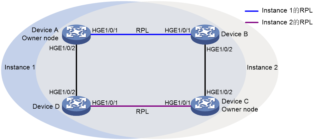
As shown in Figure 1, to improve network resource utilization and implement load balancing among links, configure ERPS as follows:
· Configure ERPS instances 1 and 2 on the ERPS ring.
· For ERPS instance 1, configure the following items:
¡ Configure Device A as the owner node.
¡ Configure the link between Devices A and Device B as the RPL.
¡ Configure VLAN 100 as the control VLAN.
¡ Configure VLANs 1 to 30 as the protected VLANs.
· For ERPS instance 2, configure the following items:
¡ Configure Device A as the owner node.
¡ Configure the link between Devices C and Device D as the RPL.
¡ Configure VLAN 100 as the control VLAN.
¡ Configure VLANs 31 to 60 as the protected VLANs.
Use Ethernet OAM to monitor the ERPS ring link status and determine if the network link reliability meets the requirements.
· Enable automatic detection of the connectivity of ERPS ring links.
· Check whether a critical link event has occurred on the ERPS ring.
· Check the statistics of Ethernet OAM link events to determine the ERPS ring status.
Analysis
An ERPS ring supports multiple ERPS instances. An ERPS instance is a logical ring to process service and protocol packets. Each ERPS instance has its own owner node and maintains its own state and data. In this example, instance 1 and instance 2 are configured on ERPS ring 1.
Common link events that can be monitored by Ethernet OAM include errored symbol events, errored frame events, errored frame period events, and errored frame seconds events. By default, the interfaces with Ethernet OAM enabled use global configuration for common link event detection parameters. To meet the detection requirements in specific network conditions, you can change the detection parameters as needed. In this example, the parameters for detecting errored frame events are changed.
Software versions used
This configuration example was created and verified on Release 5210 or later versions of S12500R.
Restrictions and guidelines
In this example, some physical interfaces must operate in bridge mode. By default, the physical interfaces on the device operate in route mode. Use the port link-mode command in the corresponding interface view to switch the interface's operating mode as needed.
By default, the interfaces on the device are in administratively down (ADM) state. You must bring up the interfaces by using the undo shutdown command in the corresponding interface view as needed.
ERPS does not provide an election mechanism. To implement ring detection and protection, configure all nodes correctly.
Do not change the Ethernet OAM connection mode on Ethernet OAM-enabled interface. To change the Ethernet OAM connection mode on an interface, first disable Ethernet OAM on that interface.
As a best practice, do not enable Ethernet OAM remote loopback on ERPS ring member ports, as it might cause a short-term broadcast storm.
The protection VLANs of different ERPS instances must be different.
Procedures
Configuring Device A
# Create VLANs 1 to 60, map VLANs 1 to 30 to MSTI 1 and VLANs 31 to 60 to MSTI 2, and activate the MST region configuration.
<DeviceA> system-view
[DeviceA] vlan 1 to 60
[DeviceA] stp region-configuration
[DeviceA-mst-region] instance 1 vlan 1 to 30
[DeviceA-mst-region] instance 2 vlan 31 to 60
[DeviceA-mst-region] active region-configuration
[DeviceA-mst-region] quit
# Set the link state change suppression interval to 0 seconds on HundredGigE 1/0/1 and HundredGigE 1/0/2, respectively. Disable the spanning tree feature on the interface and configure the interface as a trunk port and assign it to VLANs 1 to 60.
[DeviceA] interface hundredgige 1/0/1
[DeviceA-HundredGigE1/0/1] link-delay up 0
[DeviceA-HundredGigE1/0/1] link-delay down 0
[DeviceA-HundredGigE1/0/1] undo stp enable
[DeviceA-HundredGigE1/0/1] port link-type trunk
[DeviceA-HundredGigE1/0/1] port trunk permit vlan 1 to 60
[DeviceA-HundredGigE1/0/1] quit
[DeviceA] interface hundredgige 1/0/2
[DeviceA-HundredGigE1/0/2] link-delay up 0
[DeviceA-HundredGigE1/0/2] link-delay down 0
[DeviceA-HundredGigE1/0/2] undo stp enable
[DeviceA-HundredGigE1/0/2] port link-type trunk
[DeviceA-HundredGigE1/0/2] port trunk permit vlan 1 to 60
[DeviceA-HundredGigE1/0/2] quit
# Create ERPS ring 1.
[DeviceA] erps ring 1
# Configure ERPS ring member ports.
[DeviceA-erps-ring1] port0 interface hundredgige 1/0/1
[DeviceA-erps-ring1] port1 interface hundredgige 1/0/2
# Create ERPS instance 1.
[DeviceA-erps-ring1] instance 1
# Configure the node role.
[DeviceA-erps-ring1-inst1] node-role owner rpl port0
# Configure the control VLAN.
control-vlan 100 on [DeviceA-erps-ring1-inst1].
# Configure the protected VLANs.
[DeviceA-erps-ring1-inst1] protected-vlan reference-instance 1
# Enable ERPS for instance 1.
[DeviceA-erps-ring1-inst1] instance enable
[DeviceA-erps-ring1-inst1] quit
# Create ERPS instance 2.
[DeviceA-erps-ring1] instance 2
# Configure the control VLAN.
[DeviceA-erps-ring1-inst2] control-vlan 110
# Configure the protected VLANs.
[DeviceA-erps-ring1-inst2] protected-vlan reference-instance 2
# Enable ERPS for instance 2.
[DeviceA-erps-ring1-inst2] instance enable
[DeviceA-erps-ring1-inst2] quit
[DeviceA-erps-ring1] quit
# Enable ERPS.
[DeviceA] erps enable
# Configure HundredGigE 1/0/1 to operate in active Ethernet OAM mode, and enable Ethernet OAM for it. (By default, An Ethernet OAM-enabled Ethernet interface operates in active Ethernet OAM mode.) Set the errored frame event detection window to 20000 milliseconds, and set the errored frame event triggering threshold to 10.
[DeviceA] interface hundredgige 1/0/1
[DeviceA-HundredGigE1/0/1] oam mode active
[DeviceA-HundredGigE1/0/1] oam enable
[DeviceA-HundredGigE1/0/1] oam errored-frame window 200
[DeviceA-HundredGigE1/0/1] oam errored-frame threshold 10
[DeviceA-HundredGigE1/0/1] quit
# Configure HundredGigE 1/0/2 to operate in passive Ethernet OAM mode, and enable Ethernet OAM for it.
[DeviceA] interface hundredgige 1/0/2
[DeviceA-HundredGigE1/0/2] oam mode passive
[DeviceA-HundredGigE1/0/2] oam enable
[DeviceA-HundredGigE1/0/2] quit
Configuring Device B
# Create VLANs 1 to 60, map VLANs 1 to 30 to MSTI 1 and VLANs 31 to 60 to MSTI 2, and activate the MST region configuration.
<DeviceB> system-view
[DeviceB] vlan 1 to 60
[DeviceB] stp region-configuration
[DeviceB-mst-region] instance 1 vlan 1 to 30
[DeviceB-mst-region] instance 2 vlan 31 to 60
[DeviceB-mst-region] active region-configuration
[DeviceB-mst-region] quit
# Set the link state change suppression interval to 0 seconds on HundredGigE 1/0/1 and HundredGigE1/0/2, respectively. Disable the spanning tree feature on the interface and configure the interface as a trunk port and assign it to VLANs 1 to 60.
[DeviceB] interface hundredgige 1/0/1
[DeviceB-HundredGigE1/0/1] link-delay up 0
[DeviceB-HundredGigE1/0/1] link-delay down 0
[DeviceB-HundredGigE1/0/1] undo stp enable
[DeviceB-HundredGigE1/0/1] port link-type trunk
[DeviceB-HundredGigE1/0/1] port trunk permit vlan 1 to 60
[DeviceB-HundredGigE1/0/1] quit
[DeviceB] interface hundredgige 1/0/2
[DeviceB-HundredGigE1/0/2] link-delay up 0
[DeviceB-HundredGigE1/0/2] link-delay down 0
[DeviceB-HundredGigE1/0/2] undo stp enable
[DeviceB-HundredGigE1/0/2] port link-type trunk
[DeviceB-HundredGigE1/0/2] port trunk permit vlan 1 to 60
[DeviceB-HundredGigE1/0/2] quit
# Create ERPS ring 1.
[DeviceB] erps ring 1
# Configure ERPS ring member ports.
[DeviceB-erps-ring1] port0 interface hundredgige 1/0/1
[DeviceB-erps-ring1] port1 interface hundredgige 1/0/2
# Create ERPS instance 1.
[DeviceB-erps-ring1] instance 1
# Configure the node role.
[DeviceB-erps-ring1-inst1] node-role neighbor rpl port0
# Configure the control VLAN.
[DeviceB-erps-ring1-inst1] control-vlan 100
# Configure the protected VLANs.
[DeviceB-erps-ring1-inst1] protected-vlan reference-instance 1
# Enable ERPS for instance 1.
[DeviceB-erps-ring1-inst1] instance enable
[DeviceB-erps-ring1-inst1] quit
# Create ERPS instance 2.
[DeviceB-erps-ring1] instance 2
# Configure the control VLAN.
[DeviceB-erps-ring1-inst2] control-vlan 110
# Configure the protected VLANs.
[DeviceB-erps-ring1-inst2] protected-vlan reference-instance 2
# Enable ERPS for instance 2.
[DeviceB-erps-ring1-inst2] instance enable
[DeviceB-erps-ring1-inst2] quit
[DeviceB-erps-ring1] quit
# Enable ERPS.
[DeviceB] erps enable
# Configure HundredGigE 1/0/2 to operate in active Ethernet OAM mode, and enable Ethernet OAM for it. (By default, An Ethernet OAM-enabled Ethernet interface operates in active Ethernet OAM mode.) Set the errored frame event detection window to 20000 milliseconds, and set the errored frame event triggering threshold to 10.
[DeviceB] interface hundredgige 1/0/2
[DeviceB-HundredGigE1/0/2] oam mode active
[DeviceB-HundredGigE1/0/2] oam enable
[DeviceB-HundredGigE1/0/2] oam errored-frame window 200
[DeviceB-HundredGigE1/0/2] oam errored-frame threshold 10
[DeviceB-HundredGigE1/0/2] quit
# Configure HundredGigE 1/0/1 to operate in passive Ethernet OAM mode, and enable Ethernet OAM for it.
[DeviceB] interface hundredgige 1/0/1
[DeviceB-HundredGigE1/0/1] oam mode passive
[DeviceB-HundredGigE1/0/1] oam enable
[DeviceB-HundredGigE1/0/1] quit
Configuring Device C
# Create VLANs 1 to 60, map VLANs 1 to 30 to MSTI 1 and VLANs 31 to 60 to MSTI 2, and activate the MST region configuration.
<DeviceC> system-view
[DeviceC] vlan 1 to 60
[DeviceC] stp region-configuration
[DeviceC-mst-region] instance 1 vlan 1 to 30
[DeviceC-mst-region] instance 2 vlan 31 to 60
[DeviceC-mst-region] active region-configuration
[DeviceC-mst-region] quit
# Set the link state change suppression interval to 0 seconds on HundredGigE 1/0/1 and HundredGigE1/0/2, respectively. Disable the spanning tree feature on the interface and configure the interface as a trunk port and assign it to VLANs 1 to 60.
[DeviceC] interface hundredgige 1/0/1
[DeviceC-HundredGigE1/0/1] link-delay up 0
[DeviceC-HundredGigE1/0/1] link-delay down 0
[DeviceC-HundredGigE1/0/1] undo stp enable
[DeviceC-HundredGigE1/0/1] port link-type trunk
[DeviceC-HundredGigE1/0/1] port trunk permit vlan 1 to 60
[DeviceC-HundredGigE1/0/1] quit
[DeviceC] interface hundredgige 1/0/2
[DeviceC-HundredGigE1/0/2] link-delay up 0
[DeviceC-HundredGigE1/0/2] link-delay down 0
[DeviceC-HundredGigE1/0/2] undo stp enable
[DeviceC-HundredGigE1/0/2] port link-type trunk
[DeviceC-HundredGigE1/0/2] port trunk permit vlan 1 to 60
[DeviceC-HundredGigE1/0/2] quit
# Create ERPS ring 1.
[DeviceC] erps ring 1
# Configure ERPS ring member ports.
[DeviceC-erps-ring1] port0 interface hundredgige 1/0/1
[DeviceC-erps-ring1] port1 interface hundredgige 1/0/2
# Create ERPS instance 1.
[DeviceC-erps-ring1] instance 1
# Configure the control VLAN.
[DeviceC-erps-ring1-inst1] control-vlan 100
# Configure the protected VLANs.
[DeviceC-erps-ring1-inst1] protected-vlan reference-instance 1
# Enable ERPS for instance 1.
[DeviceC-erps-ring1-inst1] instance enable
[DeviceC-erps-ring1-inst1] quit
# Create ERPS instance 2.
[DeviceC-erps-ring1] instance 2
# Configure the node role.
[DeviceC-erps-ring1-inst2] node-role owner rpl port0
# Configure the control VLAN.
[DeviceC-erps-ring1-inst2] control-vlan 110
# Configure the protected VLANs.
[DeviceC-erps-ring1-inst2] protected-vlan reference-instance 2
# Enable ERPS for instance 2.
[DeviceC-erps-ring1-inst2] instance enable
[DeviceC-erps-ring1-inst2] quit
[DeviceC-erps-ring1] quit
# Enable ERPS.
[DeviceC] erps enable
# Configure HundredGigE 1/0/1 to operate in active Ethernet OAM mode, and enable Ethernet OAM for it. (By default, An Ethernet OAM-enabled Ethernet interface operates in active Ethernet OAM mode.) Set the errored frame event detection window to 20000 milliseconds, and set the errored frame event triggering threshold to 10.
[DeviceC] interface hundredgige 1/0/1
[DeviceC-HundredGigE1/0/1] oam mode active
[DeviceC-HundredGigE1/0/1] oam enable
[DeviceC-HundredGigE1/0/1] oam errored-frame window 200
[DeviceC-HundredGigE1/0/1] oam errored-frame threshold 10
[DeviceC-HundredGigE1/0/1] quit
# Configure HundredGigE 1/0/2 to operate in passive Ethernet OAM mode, and enable Ethernet OAM for it.
[DeviceC] interface hundredgige 1/0/2
[DeviceC-HundredGigE1/0/2] oam mode passive
[DeviceC-HundredGigE1/0/2] oam enable
[DeviceC-HundredGigE1/0/2] quit
Configuring Device D
# Create VLANs 1 to 60, map VLANs 1 to 30 to MSTI 1 and VLANs 31 to 60 to MSTI 2, and activate the MST region configuration.
<DeviceD> system-view
[DeviceD] vlan 1 to 60
[DeviceD] stp region-configuration
[DeviceD-mst-region] instance 1 vlan 1 to 30
[DeviceD-mst-region] instance 2 vlan 31 to 60
[DeviceD-mst-region] active region-configuration
[DeviceD-mst-region] quit
# Set the link state change suppression interval to 0 seconds on HundredGigE 1/0/1 and HundredGigE1/0/2, respectively. Disable the spanning tree feature on the interface and configure the interface as a trunk port and assign it to VLANs 1 to 60.
[DeviceD] interface hundredgige 1/0/1
[DeviceD-HundredGigE1/0/1] link-delay up 0
[DeviceD-HundredGigE1/0/1] link-delay down 0
[DeviceD-HundredGigE1/0/1] undo stp enable
[DeviceD-HundredGigE1/0/1] port link-type trunk
[DeviceD-HundredGigE1/0/1] port trunk permit vlan 1 to 60
[DeviceD-HundredGigE1/0/1] quit
[DeviceD] interface hundredgige 1/0/2
[DeviceD-HundredGigE1/0/2] link-delay up 0
[DeviceD-HundredGigE1/0/2] link-delay down 0
[DeviceD-HundredGigE1/0/2] undo stp enable
[DeviceD-HundredGigE1/0/2] port link-type trunk
[DeviceD-HundredGigE1/0/2] port trunk permit vlan 1 to 60
[DeviceD-HundredGigE1/0/2] quit
# Create ERPS ring 1.
[DeviceD] erps ring 1
# Configure ERPS ring member ports.
[DeviceD-erps-ring1] port0 interface hundredgige 1/0/1
[DeviceD-erps-ring1] port1 interface hundredgige 1/0/2
# Create ERPS instance 1.
[DeviceD-erps-ring1] instance 1
# Configure the control VLAN.
[DeviceD-erps-ring1-inst1] control-vlan 100
# Configure the protected VLANs.
[DeviceD-erps-ring1-inst1] protected-vlan reference-instance 1
# Enable ERPS for instance 1.
[DeviceD-erps-ring1-inst1] instance enable
[DeviceD-erps-ring1-inst1] quit
# Create ERPS for instance 2.
[DeviceD-erps-ring1] instance 2
# Configure the node role.
[DeviceD-erps-ring1-inst2] node-role neighbor rpl port0
# Configure the control VLAN.
[DeviceD-erps-ring1-inst2] control-vlan 110
# Configure the protected VLANs.
[DeviceD-erps-ring1-inst2] protected-vlan reference-instance 2
# Enable ERPS for instance 1.
[DeviceD-erps-ring1-inst2] instance enable
[DeviceD-erps-ring1-inst2] quit
[DeviceD-erps-ring1] quit
# Enable ERPS.
[DeviceD] erps enable
# Configure HundredGigE 1/0/2 to operate in active Ethernet OAM mode, and enable Ethernet OAM for it. (By default, An Ethernet OAM-enabled Ethernet interface operates in active Ethernet OAM mode.) Set the errored frame event detection window to 20000 milliseconds, and set the errored frame event triggering threshold to 10.
[DeviceD] interface hundredgige 1/0/2
[DeviceD-HundredGigE1/0/2] oam mode active
[DeviceD-HundredGigE1/0/2] oam enable
[DeviceD-HundredGigE1/0/2] oam errored-frame window 200
[DeviceD-HundredGigE1/0/2] oam errored-frame threshold 10
[DeviceD-HundredGigE1/0/2] quit
# Configure HundredGigE 1/0/1 to operate in passive Ethernet OAM mode, and enable Ethernet OAM for it.
[DeviceD] interface hundredgige 1/0/1
[DeviceD-HundredGigE1/0/1] oam mode passive
[DeviceD-HundredGigE1/0/1] oam enable
[DeviceD-HundredGigE1/0/1] quit
Verifying the configuration
# Display information about ERPS instance 1 for Device A.
[Device A] display erps detail ring 1
Ring ID : 1
Port0 : HundredGigE1/0/1
Port1 : HundredGigE1/0/2
Subring : No
Default MAC : No
Instance ID : 1
Node role : Owner
Node state : Idle
Connect(ring/instance): -
Control VLAN : 100
Protected VLAN : Reference-instance 1
Guard timer : 500 ms
Hold-off timer : 0 ms
WTR timer : 5 min
Revertive operation : Revertive
Enable status : Yes, Active status : Yes
R-APS level : 7
Port PortRole PortStatus
----------------------------------------------------------------------------
Port0 RPL Block
Port1 Non-RPL Up
Instance ID : 2
Node role : Normal
Node state : Idle
Connect(ring/instance): -
Control VLAN : 100
Protected VLAN : Reference-instance 2
Guard timer : 500 ms
Hold-off timer : 0 ms
WTR timer : 5 min
Revertive operation : Revertive
Enable status : Yes, Active status : Yes
R-APS level : 7
Port PortRole PortStatus
----------------------------------------------------------------------------
Port0 Non-RPL Up
Port1 Non-RPL Up
The output shows the following information:
In instance 1:
· Device A is the owner node.
· The ERPS ring is in idle state.
· The RPL port is blocked.
· The non-RPL port is unblocked.
In instance 2:
· Device A is a normal node.
· The ERPS ring is in idle state.
· The non-RPL port is unblocked.
# Display global Ethernet OAM configuration information and Ethernet OAM configuration information on interfaces that have not used the default configuration for Device A.
[DeviceA] display oam configuration
---------------- [Global] ----------------
OAM timers
Hello timer : 1000 milliseconds
Keepalive timer : 5000 milliseconds
Link monitoring
Errored symbol period
Window : 100 x 1000000 symbols
Threshold : 1 error symbols
Errored frame
Window : 10 x 100 milliseconds
Threshold : 1 error frames
Errored frame period
Window : 1000 x 10000 frames
Threshold : 1 error frames
Errored frame seconds
Window : 600 x 100 milliseconds
Threshold : 1 error seconds
----------- [HundredGigE1/0/1] -----------
OAM timers
Hello timer : 1000 milliseconds
Keepalive timer : 5000 milliseconds
Link monitoring
Errored symbol period
Window : 100 x 1000000 symbols
Threshold : 1 error symbols
Errored frame
Window : 200 x 100 milliseconds
Threshold : 10 error frames
Errored frame period
Window : 1000 x 10000 frames
Threshold : 1 error frames
Errored frame seconds
Window : 600 x 100 milliseconds
Threshold : 1 error seconds
# Display the statistics about Ethernet OAM critical link events for Device A.
[DeviceA] display oam critical-event
----------- [HundredGigE1/0/1] -----------
Local link status : UP
Event statistics
Link fault : Not occurred
Dying gasp : Not occurred
Critical event : Not occurred
The command output shows that the link between Device A and Device B is normal and no critical link event has occurred on the link.
# Display Ethernet OAM link event statistics of the local end of Device A.
[DeviceA] display oam link-event local
----------- [HundredGigE1/0/1] -----------
Link status: UP
OAM local errored frame event
Event time stamp : 5789 x 100 milliseconds
Errored frame window : 200 x 100 milliseconds
Errored frame threshold : 10 error frames
Errored frame : 13 error frames
Error running total : 350 error frames
Event running total : 17 events
The output shows the following:
· 350 errors has occurred after Ethernet OAM is enabled on Device A.
· 17 errors were caused by error frames.
· The link is unstable.
|
|
NOTE: If the link performance is detected unstable, contact H3C Technical Support. |
Configuration files
· Device A
#
vlan 1 to 60
stp region-configuration
instance 1 vlan 1 to 30
instance 2 vlan 31 to 60
active region-configuration
#
interface hundredgige 1/0/1
link-delay up 0
link-delay down 0
undo stp enable
port link-type trunk
port trunk permit vlan 1 to 60
oam mode active
oam enable
oam errored-frame window 200
oam errored-frame threshold 10
#
interface hundredgige 1/0/2
link-delay up 0
link-delay down 0
undo stp enable
port link-type trunk
port trunk permit vlan 1 to 60
oam mode passive
oam enable
#
erps ring 1
port0 interface hundredgige 1/0/1
port1 interface hundredgige 1/0/2
instance 1
node-role owner rpl port0
control-vlan 100
protected-vlan reference-instance 1
instance enable
instance 2
control-vlan 110
protected-vlan reference-instance 2
instance enable
#
erps enable
#
· Device B
#
vlan 1 to 60
stp region-configuration
instance 1 vlan 1 to 30
instance 2 vlan 31 to 60
active region-configuration
#
interface hundredgige 1/0/1
link-delay up 0
link-delay down 0
undo stp enable
port link-type trunk
port trunk permit vlan 1 to 60
oam mode passive
oam enable
#
interface hundredgige 1/0/2
link-delay up 0
link-delay down 0
undo stp enable
port link-type trunk
port trunk permit vlan 1 to 60
oam mode active
oam enable
oam errored-frame window 200
oam errored-frame threshold 10
#
erps ring 1
port0 interface hundredgige 1/0/1
port1 interface hundredgige 1/0/2
instance 1
node-role owner rpl port0
control-vlan 100
protected-vlan reference-instance 1
instance enable
instance 2
control-vlan 110
protected-vlan reference-instance 2
instance enable
#
erps enable
#
· Device C
#
vlan 1 to 60
stp region-configuration
instance 1 vlan 1 to 30
instance 2 vlan 31 to 60
active region-configuration
#
interface hundredgige 1/0/1
link-delay up 0
link-delay down 0
undo stp enable
port link-type trunk
port trunk permit vlan 1 to 60
oam mode active
oam enable
oam errored-frame window 200
oam errored-frame threshold 10
#
interface hundredgige 1/0/2
link-delay up 0
link-delay down 0
undo stp enable
port link-type trunk
port trunk permit vlan 1 to 60
oam mode passive
oam enable
#
erps ring 1
port0 interface hundredgige 1/0/1
port1 interface hundredgige 1/0/2
instance 1
control-vlan 100
protected-vlan reference-instance 1
instance enable
instance 2
node-role owner rpl port0
control-vlan 110
protected-vlan reference-instance 2
instance enable
#
erps enable
#
· Device D
#
vlan 1 to 60
stp region-configuration
instance 1 vlan 1 to 30
instance 2 vlan 31 to 60
active region-configuration
#
interface hundredgige 1/0/1
link-delay up 0
link-delay down 0
undo stp enable
port link-type trunk
port trunk permit vlan 1 to 60
oam mode passive
oam enable
#
interface hundredgige 1/0/2
link-delay up 0
link-delay down 0
undo stp enable
port link-type trunk
port trunk permit vlan 1 to 60
oam mode passive
oam enable
oam mode active
oam enable
oam errored-frame window 200
oam errored-frame threshold 10
#
erps ring 1
port0 interface hundredgige 1/0/1
port1 interface hundredgige 1/0/2
instance 1
control-vlan 100
protected-vlan reference-instance 1
instance enable
instance 2
node-role owner rpl port0
control-vlan 110
protected-vlan reference-instance 2
instance enable
#
erps enable
#
Related documentation
· High Availability Configuration Guide in H3C S12500R Switch Router Series Configuration Guides-R52xx
· High Availability Command Reference in H3C S12500R Switch Router Series Command References-R52xx
· High Availability Configuration Guide in H3C S12500R-48Y8C&S12500R-48C6D Switch Router Configuration Guides-R52xx
· High Availability Command Reference in H3C S12500R-48Y8C&S12500R-48C6D Switch Router Command References-R52xx