- Table of Contents
-
- H3C S12500R Ethernet Switch Router Series Config Examples-6W101
- 01-Login Management Configuration Examples
- 02-RBAC Configuration Examples
- 03-Software Upgrade Examples
- 04-Ethernet Link Aggregation Configuration Examples
- 05-Port Isolation Configuration Examples
- 06-Spanning Tree Configuration Examples
- 07-VLAN Configuration Examples
- 08-VLAN Tagging Configuration Examples
- 09-DHCP Snooping Configuration Examples
- 10-Cross-Subnet Dynamic IP Address Allocation Configuration Examples
- 11-IPv6 over IPv4 Tunneling with OSPFv3 Configuration Examples
- 12-GRE Tunnel Configuration Examples
- 13-GRE with OSPF Configuration Examples
- 14-OSPF Configuration Examples
- 15-IS-IS Configuration Examples
- 16-BGP Configuration Examples
- 17-Policy-Based Routing Configuration Examples
- 18-OSPFv3 Configuration Examples
- 19-IPv6 IS-IS Configuration Examples
- 20-Routing Policy Configuration Examples
- 21-IGMP Snooping Configuration Examples
- 22-IGMP Configuration Examples
- 23-MLD Snooping Configuration Examples
- 24-Basic MPLS Configuration Examples
- 25-MPLS L3VPN Configuration Examples
- 26-ACL Configuration Examples
- 27-Control Plane-Based QoS Policy Configuration Examples
- 28-Traffic Policing Configuration Examples
- 29-GTS and Rate Limiting Configuration Examples
- 30-Priority Mapping and Queue Scheduling Configuration Examples
- 31-Traffic Filtering Configuration Examples
- 32-AAA Configuration Examples
- 33-SSH Configuration Examples
- 34-IP Source Guard Configuration Examples
- 35-Ethernet OAM Configuration Examples
- 36-CFD Configuration Examples
- 37-DLDP Configuration Examples
- 38-VRRP Configuration Examples
- 39-BFD Configuration Examples
- 40-NTP Configuration Examples
- 41-SNMP Configuration Examples
- 42-NQA Configuration Examples
- 43-Mirroring Configuration Examples
- 44-sFlow Configuration Examples
- 45-OpenFlow Configuration Examples
- 46-MAC Address Table Configuration Examples
- 47-Static Multicast MAC Address Entry Configuration Examples
- 48-IP Unnumbered Configuration Examples
- 49-Congestion Avoidance and Queue Scheduling Configuration Examples
- 50-Attack Protection Configuration Examples
- 51-Smart Link Configuration Examples
- 52-RRPP Configuration Examples
- 53-BGP Route Selection Configuration Examples
- 54-IS-IS Route Summarization Configuration Examples
- 55-MPLS OAM Configuration Examples
- 56-MPLS TE Configuration Examples
- 57-VXLAN Configuration Examples
- 58-NetStream Configuration Examples
- 59-EVPN-DCI over an MPLS L3VPN Network Configuration Examples
- 60-PTP Configuration Examples
- 61-S-MLAG Configuration Examples
- 62-MPLS SR Configuration Examples
- 63-Puppet Configuration Examples
- 64-Configuration Example of Using Ethernet OAM to Monitor ERPS Ring Link Performance
- 65-GRE Tunneling Between DHCP Relay and DHCP Server Configuration Examples
- 66-Loop Detection Configuration Examples
- 67-MPLS L3VPN+VRRP Configuration Examples
- 68-MSTP and VRRP Load Balancing Configuration Examples
- 69-Routing Policy for VPN Access Control Configuration Examples
- 70-Switch and Firewall Connection Configuration Examples for External Network Access
- 71-Switch and Router Connection Configuration Examples for External Network Access
- 72-VRRP Network Multicast Data Transmission Configuration Examples
- Related Documents
-
| Title | Size | Download |
|---|---|---|
| 66-Loop Detection Configuration Examples | 116.11 KB |
|
|
|
H3C S12500R Switch Router Series |
|
Loop Detection Configuration Examples |
|
|
Copyright © 2024 New H3C Technologies Co., Ltd. All rights reserved.
No part of this manual may be reproduced or transmitted in any form or by any means without prior written consent of New H3C Technologies Co., Ltd.
Except for the trademarks of New H3C Technologies Co., Ltd., any trademarks that may be mentioned in this document are the property of their respective owners.
The information in this document is subject to change without notice.
Contents
Example: Configuring loop detection to detect loops in an attached network
Applicable hardware and software versions
Example: Configuring loop detection to detect self loops on interfaces
Applicable hardware and software versions
Introduction
The following information provides loop detection configuration examples.
The configuration examples were created and verified in a lab environment, and all the devices were started with the factory default configuration. When you are working on a live network, make sure you understand the potential impact of every command on your network.
The following information is provided based on the assumption that you have basic knowledge of loop detection.
Restrictions and guidelines
By default, interfaces on the device are disabled (in ADM or Administratively Down state). To have an interface operate, you must use the undo shutdown command to enable that interface.
Some physical interfaces in this example must operate in bridge (Layer 2) mode. By default, the physical interfaces on the device operate in routed (Layer 3) mode. To change the link mode of a physical interface, use the port link-mode command.
Example: Configuring loop detection to detect loops in an attached network
Network configuration
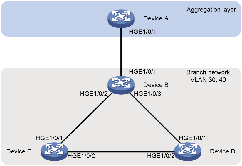
As shown in Figure 1, the branch network of an organization is connected to the aggregation layer device (Device A). The branch network uses VLANs 30 and 40. A risk of loop exists in the branch network, which could cause a broadcast storm and affect the normal communication of Device A and its upstream network.
Configure loop detection feature on Device A to detect whether loops exist in the branch network connected to it. When a loop exists, block the port connected to the branch network to prevent loops in the downstream network from affecting Device A and its upstream network.
Restrictions and guidelines
The loop detection feature is mutually exclusive with other protocols that have Layer 2 loop prevention capabilities, such as spanning tree, RRPP, and ERPS. Do not enable them simultaneously on the device.
The loop detection feature consumes system resources. If enabling it causes CPU or memory-related alarms on the device, you can configure the loopback-detection interval-time command in the system view to increase the interval time for loop detection, reducing the impact on system performance.
Applicable hardware and software versions
The following matrix shows the hardware and software versions to which this configuration example is applicable:
|
Hardware |
Software version |
|
S12500R |
Release 5210 and later |
Procedures
Configuring Device A
# Create VLAN 30 and VLAN 40 on Device A.
<DeviceA> system-view
[DeviceA] vlan 30 40
# Configure HundredGigE 1/0/1 as a trunk port, and assign it to VLAN 30 and VLAN 40.
[DeviceA] interface hundredgige 1/0/1
[DeviceA-HundredGigE1/0/1] port link-type trunk
[DeviceA-HundredGigE1/0/1] port trunk permit vlan 30 40
# Set the global loop protection action to block, and enable loop detection for the VLAN 30 and VLAN 40.
[DeviceA-HundredGigE1/0/1] loopback-detection action block
[DeviceA-HundredGigE1/0/1] loopback-detection enable vlan 30 40
|
|
IMPORTANT: The block action will block the interfaces that detect a loop, preventing them from receiving user data packets. These ports can still receive control plane protocol packets, such as loop detection packets. If you want to completely eliminate the impact of the downstream network on Device A or still want to receive data packets from the looped network, you can configure the following alternative loop detection processing modes on the ports. · No-learning—Disables the interface from learning MAC addresses using the loopback-detection action no-learning command. · Shutdown—Shuts down the interface to disable it from receiving and sending any frames using the loopback-detection action shutdown command. After a period, the port will automatically restore, causing a loop to reoccur, and the interface will be shut down again. To change the time the port automatically recovers, execute the shutdown-interval command in the system view. |
# Disable the spanning tree feature on HundredGigE 1/0/1.
[DeviceA-HundredGigE1/0/1] undo stp enable
Configuring Device B
# Create VLAN 30 and VLAN 40 on Device B.
<DeviceB> system-view
[DeviceB] vlan 30 40
# Configure HundredGigE 1/0/1, HundredGigE 1/0/2, and HundredGigE 1/0/3 as trunk ports, and assign them to VLAN 30 and VLAN 40.
[DeviceB] interface range hundredgige 1/0/1 to hundredgige 1/0/3
[DeviceB-if-range] port link-type trunk
[DeviceB-if-range] port trunk permit vlan 30 40
[DeviceB-if-range] quit
# Disable the spanning tree feature on Device B globally.
[DeviceB] undo stp global enable
Configuring Device C
# Create VLAN 30 and VLAN 40 on Device C.
<DeviceC> system-view
[DeviceC] vlan 30 40
# Configure HundredGigE 1/0/1 and HundredGigE 1/0/2 as trunk ports, and assign them to VLAN 30 and VLAN 40.
[DeviceC] interface range hundredgige 1/0/1 to hundredgige 1/0/2
[DeviceC-if-range] port link-type trunk
[DeviceC-if-range] port trunk permit vlan 30 40
[DeviceC-if-range] quit
# Disable the spanning tree feature on Device C globally.
[DeviceC] undo stp global enable
Configuring Device D
Configure Device D in the same way Device C is configured. (Details not shown.)
Verifying the configuration
# Execute the display loopback-detection command on Device A to display the loop detection configuration and status.
<DeviceA> display loopback-detection
Loop detection is enabled.
Global loop detection interval is 30 second(s).
Loop is detected on following interfaces:
Interface Action mode VLANs/VSI
HundredGigE1/0/1 Block 30 40
|
|
IMPORTANT: For the shutdown action, the interface is shut down immediately after the device detects a loop in some VLANs, causing the loop to be eliminated. In this case, the display loopback-detection command might not display all the VLANs where loops occurred. |
Configuration files
· Device A:
#
vlan 1
#
vlan 30
#
vlan 40
#
interface HundredGigE1/0/1
port link-mode bridge
port link-type trunk
port trunk permit vlan 1 30 40
undo stp enable
loopback-detection enable vlan 30 40
loopback-detection action block
#
· Device B:
#
vlan 1
#
vlan 30
#
vlan 40
#
interface HundredGigE1/0/1
port link-mode bridge
port link-type trunk
port trunk permit vlan 1 30 40
#
interface HundredGigE1/0/2
port link-mode bridge
port link-type trunk
port trunk permit vlan 1 30 40
#
interface HundredGigE1/0/3
port link-mode bridge
port link-type trunk
port trunk permit vlan 1 30 40
· Device C:
#
vlan 1
#
vlan 30
#
vlan 40
#
interface HundredGigE1/0/1
port link-mode bridge
port link-type trunk
port trunk permit vlan 1 30 40
#
interface HundredGigE1/0/2
port link-mode bridge
port link-type trunk
port trunk permit vlan 1 30 40
· Device D:
Configuration files on Device D are similar to Device C.
Example: Configuring loop detection to detect self loops on interfaces
Network configuration
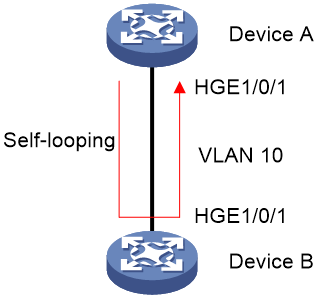
As shown in Figure 2, the aggregation device (Device A) connects to the access layer device (Device B) through a single port. In cases of misconnected or damaged links, HundredGigE 1/0/1 of Device A might experience loopback, where packets sent from this port circulate back to itself after going through the loop on the port.
Configure loop detection on HundredGigE 1/0/1 of Device A to detect any loops on this port. When a loop is detected, block the ports of the access branch network to prevent the impact of port loopback on Device A and its network.
Restrictions and guidelines
The loop detection feature is mutually exclusive with other protocols that have Layer 2 loop prevention capabilities, such as spanning tree, RRPP, and ERPS. Do not enable them simultaneously on the device.
The loop detection feature consumes system resources. If enabling it causes CPU or memory-related alarms on the device, you can configure the loopback-detection interval-time command in the system view to increase the interval time for loop detection, reducing the impact on system performance.
This configuration example only configures Device A.
Applicable hardware and software versions
The following matrix shows the hardware and software versions to which this configuration example is applicable:
|
Hardware |
Software version |
|
S12500R |
Release 5210 and later |
Procedures
Configuring Device A
# Create VLAN 10 on Device A.
<DeviceA> system-view
[DeviceA] vlan 10
# Configure HundredGigE 1/0/1 as a trunk port, and assign it to VLAN 10.
[DeviceA] interface hundredgige 1/0/1
[DeviceA-HundredGigE1/0/1] port link-type trunk
[DeviceA-HundredGigE1/0/1] port trunk permit vlan 10
# Set the loop protection action to block on HundredGigE 1/0/1, and enable loop detection for the VLAN 10.
[DeviceA-HundredGigE1/0/1] loopback-detection action block
[DeviceA-HundredGigE1/0/1] loopback-detection enable vlan 10
|
|
IMPORTANT: The block action will block the interfaces that detect a loop, preventing them from receiving user data packets. These ports can still receive control plane protocol packets, such as loop detection packets. If you want to completely eliminate the impact of the downstream network on Device A or still want to receive data packets from the looped network, you can configure the following alternative loop detection processing modes on the ports. · No-learning—Disables the interface from learning MAC addresses using the loopback-detection action no-learning command. · Shutdown—Shuts down the interface to disable it from receiving and sending any frames using the loopback-detection action shutdown command. After a period, the port will automatically restore, causing a loop to reoccur, and the interface will be shut down again. To change the time the port automatically recovers, execute the shutdown-interval command in the system view. |
# Disable the spanning tree feature on HundredGigE 1/0/1.
[DeviceA-HundredGigE1/0/1] undo stp enable
Verifying the configuration
# Execute the display loopback-detection command on Device A to display the loop detection configuration and status.
<DeviceA> display loopback-detection
Loop detection is enabled.
Global loop detection interval is 30 second(s).
Loop is detected on following interfaces:
Interface Action mode VLANs/VSI
HundredGigE1/0/1 Block 10
|
|
IMPORTANT: For the shutdown action, the interface is shut down immediately after the device detects a loop in some VLANs, causing the loop to be eliminated. In this case, the display loopback-detection command might not display all the VLANs where loops occurred. |
Configuration files
· Device A:
#
vlan 1
#
vlan 10
#
interface HundredGigE1/0/1
port link-mode bridge
port link-type trunk
port trunk permit vlan 1 10
undo stp enable
loopback-detection enable vlan 10
loopback-detection action block
#
Related documentation
· Layer 2—LAN Switching Configuration Guide in H3C S12500R Switch Router Series Configuration Guides-R52xx
· Layer 2—LAN Switching Command Reference in H3C S12500R Switch Router Series Command References-R52xx
· Layer 2—LAN Switching Configuration Guide in H3C S12500R-48Y8C&S12500R-48C6D Switch Router Configuration Guides-R52xx
· Layer 2—LAN Switching Command Reference in H3C S12500R-48Y8C&S12500R-48C6D Switch Router Command References-R52xx