- Table of Contents
-
- H3C S12500R Ethernet Switch Router Series Config Examples-6W101
- 01-Login Management Configuration Examples
- 02-RBAC Configuration Examples
- 03-Software Upgrade Examples
- 04-Ethernet Link Aggregation Configuration Examples
- 05-Port Isolation Configuration Examples
- 06-Spanning Tree Configuration Examples
- 07-VLAN Configuration Examples
- 08-VLAN Tagging Configuration Examples
- 09-DHCP Snooping Configuration Examples
- 10-Cross-Subnet Dynamic IP Address Allocation Configuration Examples
- 11-IPv6 over IPv4 Tunneling with OSPFv3 Configuration Examples
- 12-GRE Tunnel Configuration Examples
- 13-GRE with OSPF Configuration Examples
- 14-OSPF Configuration Examples
- 15-IS-IS Configuration Examples
- 16-BGP Configuration Examples
- 17-Policy-Based Routing Configuration Examples
- 18-OSPFv3 Configuration Examples
- 19-IPv6 IS-IS Configuration Examples
- 20-Routing Policy Configuration Examples
- 21-IGMP Snooping Configuration Examples
- 22-IGMP Configuration Examples
- 23-MLD Snooping Configuration Examples
- 24-Basic MPLS Configuration Examples
- 25-MPLS L3VPN Configuration Examples
- 26-ACL Configuration Examples
- 27-Control Plane-Based QoS Policy Configuration Examples
- 28-Traffic Policing Configuration Examples
- 29-GTS and Rate Limiting Configuration Examples
- 30-Priority Mapping and Queue Scheduling Configuration Examples
- 31-Traffic Filtering Configuration Examples
- 32-AAA Configuration Examples
- 33-SSH Configuration Examples
- 34-IP Source Guard Configuration Examples
- 35-Ethernet OAM Configuration Examples
- 36-CFD Configuration Examples
- 37-DLDP Configuration Examples
- 38-VRRP Configuration Examples
- 39-BFD Configuration Examples
- 40-NTP Configuration Examples
- 41-SNMP Configuration Examples
- 42-NQA Configuration Examples
- 43-Mirroring Configuration Examples
- 44-sFlow Configuration Examples
- 45-OpenFlow Configuration Examples
- 46-MAC Address Table Configuration Examples
- 47-Static Multicast MAC Address Entry Configuration Examples
- 48-IP Unnumbered Configuration Examples
- 49-Congestion Avoidance and Queue Scheduling Configuration Examples
- 50-Attack Protection Configuration Examples
- 51-Smart Link Configuration Examples
- 52-RRPP Configuration Examples
- 53-BGP Route Selection Configuration Examples
- 54-IS-IS Route Summarization Configuration Examples
- 55-MPLS OAM Configuration Examples
- 56-MPLS TE Configuration Examples
- 57-VXLAN Configuration Examples
- 58-NetStream Configuration Examples
- 59-EVPN-DCI over an MPLS L3VPN Network Configuration Examples
- 60-PTP Configuration Examples
- 61-S-MLAG Configuration Examples
- 62-MPLS SR Configuration Examples
- 63-Puppet Configuration Examples
- 64-Configuration Example of Using Ethernet OAM to Monitor ERPS Ring Link Performance
- 65-GRE Tunneling Between DHCP Relay and DHCP Server Configuration Examples
- 66-Loop Detection Configuration Examples
- 67-MPLS L3VPN+VRRP Configuration Examples
- 68-MSTP and VRRP Load Balancing Configuration Examples
- 69-Routing Policy for VPN Access Control Configuration Examples
- 70-Switch and Firewall Connection Configuration Examples for External Network Access
- 71-Switch and Router Connection Configuration Examples for External Network Access
- 72-VRRP Network Multicast Data Transmission Configuration Examples
- Related Documents
-
| Title | Size | Download |
|---|---|---|
| 65-GRE Tunneling Between DHCP Relay and DHCP Server Configuration Examples | 134.75 KB |
|
|
|
H3C S12500R Switch Router Series |
|
GRE Tunneling Between DHCP Relay and DHCP Server Configuration Examples |
|
|
Copyright © 2024 New H3C Technologies Co., Ltd. All rights reserved.
No part of this manual may be reproduced or transmitted in any form or by any means without prior written consent of New H3C Technologies Co., Ltd.
Except for the trademarks of New H3C Technologies Co., Ltd., any trademarks that may be mentioned in this document are the property of their respective owners.
The information in this document is subject to change without notice.
Contents
Example: Interconnecting DHCP relay and DHCP server with GRE tunnels
Applicable hardware and software versions
Introduction
When the DHCP client and the DHCP server are located on different physical networks, the client can obtain IP addresses and other configuration information from the server through DHCP relay.
DHCP relay simplifies and facilitates network management. With this feature, you can achieve centralized DHCP server configuration and management by configuring the DHCP server function on devices at the core layer or configuring dedicated DHCP servers in the DHCP server area. You do not need to configure the DHCP server function on each device (user gateway) at the convergence layer.
When the DHCP relay and the DHCP server are in different areas, you can interconnect them with VPN tunnels (such as GRE and MPLS VPN tunnels) across the WAN.
This document introduces a configuration example of interconnecting DHCP relay and DHCP server with GRE tunnels.
Prerequisites
The configuration examples were created and verified in a lab environment, and all the devices were started with the factory default configuration. When you are working on a live network, make sure you understand the potential impact of every command on your network. If you have configured the devices before performing this configuration task, make sure that the existing configuration does not conflict with the configuration in the following example.
The following information is provided based on the assumption that you have basic knowledge of DHCP, OSPF, and GRE.
Restrictions and guidelines
By default, interfaces on the device are disabled (in ADM or Administratively Down state). To have an interface operate, you must use the undo shutdown command to enable that interface.
Some physical interfaces in this example must operate in bridge (Layer 2) mode. By default, the physical interfaces on the device operate in routed (Layer 3) mode. To change the link mode of a physical interface, use the port link-mode command.
Example: Interconnecting DHCP relay and DHCP server with GRE tunnels
Network configuration
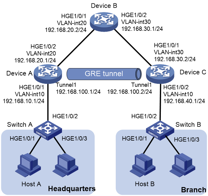
As shown in the following figure, Device A is the headquarters gateway of an organization and Device C is the branch gateway. Device A, Device B, and Device C are interconnected over IPv4 networks. Specific network requirements are as follows:
· The headquarters and the branch can access each other through GRE tunnels
· Device A acts as the DHCP server and Device C acts as the DHCP relay. Device A can assign IP addresses to endpoints at the branch and the headquarters.
· Device A, Device B, and Device C run OSPF to ensure that they can reach each other.
|
Interface |
IP address |
|
|
Device A |
Vlan-int10 |
192.168.10.1/24 |
|
Vlan-int20 |
192.168.20.1/24 |
|
|
Tunnel 1 |
192.168.100.1/24 |
|
|
Device B |
Vlan-int20 |
192.168.20.2./24 |
|
Vlan-int30 |
192.168.30.1/24 |
|
|
Device C |
Vlan-int30 |
192.168.30.2/24 |
|
Vlan-int10 |
192.168.40.1/24 |
|
|
Tunnel 1 |
192.168.100.2/24 |
Analysis
1. Run OSPF on Device A, Device B, and Device C to ensure that they can reach each other.
2. Configure tunnel interfaces on Device A and Device C, and then configure a GRE tunnel to connect the two devices.
3. Enable the DHCP server function on Device A, so it can assign IP addresses from the global address pool to endpoints at the headquarters and the branch.
4. Configure the DHCP relay function on Device C, so endpoints at the branch can exchange DHCP messages with the DHCP server for IP address acquisition.
5. Configure static routes destined for the headquarters network and the branch network, because only Device A, Device B, and Device C run OSPF.
Applicable hardware and software versions
The following matrix shows the hardware and software versions to which this configuration example is applicable:
|
Hardware |
Software version |
|
S12500R switch series |
Release 5210 and later |
Restrictions and guidelines
· Both ends of the GRE tunnel must be configured with source and destination addresses. The source address and destination address configured on the local end must be the same as the destination address and source address configured on the remote end, respectively.
· Encapsulated packets cannot be forwarded twice at Layer 3 based on destination address and routing table. To resolve this issue, send encapsulated packets to the service loopback group, which will then return those packets to the forwarding module for Layer 3 forwarding. Therefore, to achieve tunnel packet reception and transmission, you need to create a tunnel-type service loopback group.
Procedures
The following configuration steps assume that all device interfaces are routed ports by default.
Configuring Device A
Configuring VLANs and assigning IP addresses to VLAN interfaces
<DeviceA> system-view
[DeviceA] vlan 10 20
[DeviceA] interface vlan-interface 10
[DeviceA-Vlan-interface10] ip address 192.168.10.1 24
[DeviceA-Vlan-interface10] quit
[DeviceA] interface vlan-interface 20
[DeviceA-Vlan-interface20] ip address 192.168.20.1 24
[DeviceA-Vlan-interface20] quit
[DeviceA] interface hundredgige 1/0/1
[DeviceA-HundredGigE1/0/1] port link-mode bridge
The configuration of the interface will be restored to the default. Continue? [Y/N]:y
[DeviceA-HundredGigE1/0/1] port link-type trunk
[DeviceA-HundredGigE1/0/1] port trunk permit vlan 10
[DeviceA-HundredGigE1/0/1] quit
[DeviceA] interface hundredgige 1/0/2
[DeviceA-HundredGigE1/0/2] port link-mode bridge
The configuration of the interface will be restored to the default. Continue? [Y/N]:y
[DeviceA-HundredGigE1/0/2] port link-type trunk
[DeviceA-HundredGigE1/0/2] port trunk permit vlan 20
[DeviceA-HundredGigE1/0/2] quit
Enabling OSPF
# Configure a unique global router ID for Device A.
|
|
NOTE: Devices in the same AS must use different global router Ids. To ensure that the router ID of a router is unique in the AS, specify the IP address of an interface on that router as the router ID. |
[DeviceA] router id 192.168.10.1
# Configure a network for an OSPF area and enable OSPF on the interfaces attached to the specified network.
[DeviceA] ospf 1
[DeviceA-ospf-1] area 0
[DeviceA-ospf-1-area-0.0.0.0] network 192.168.20.0 0.0.0.255
[DeviceA-ospf-1-area-0.0.0.0] quit
[DeviceA-ospf-1] quit
Configuring GRE tunnels
# Create service loopback group 1 and configure its service type as tunnel.
[DeviceA] service-loopback group 1 type tunnel
# Add HundredGigE 1/0/3 into service loopback group 1.
[DeviceA] interface hundredgige 1/0/3
[DeviceA-HundredGigE1/0/3] port link-mode bridge
The configuration of the interface will be restored to the default. Continue? [Y/N]:y
[DeviceA-HundredGigE1/0/3] port service-loopback group 1
All configurations on the interface will be lost. Continue?[Y/N]:y
[DeviceA-HundredGigE1/0/3] quit
# Create tunnel interface Tunnel1 and specify it tunnel mode as GRE over IPv4.
[DeviceA]interface Tunnel 1 mode gre
# Configure an IP address for tunnel interface Tunnel1
[DeviceA-Tunnel1] ip address 192.168.100.1 24
# Specify a source address for the GRE tunnel.
[DeviceA-Tunnel1] source 192.168.20.1
# Specify a destination address for the GRE tunnel.
[DeviceA-Tunnel1] destination 192.168.30.2
[DeviceA-Tunnel1] quit
Configuring Device A as the DHCP server
# Enable VLAN-interface 10 to operate in DHCP server mode.
[DeviceA] interface vlan-interface 10
[DeviceA-Vlan-interface10] dhcp select server
[DeviceA-Vlan-interface10] quit
# Configure DHCP address pool 1 for IP address assignment to endpoints at the branch.
[DeviceA] dhcp server ip-pool 1
[DeviceA-dhcp-pool-1] network 192.168.40.0 24
[DeviceA-dhcp-pool-1] gateway-list 192.168.40.1
[DeviceA-dhcp-pool-1] quit
# Configure DHCP address pool 2 for IP address assignment to endpoints at the headquarters.
[DeviceA] dhcp server ip-pool 2
[DeviceA-dhcp-pool-2] network 192.168.10.0 24
[DeviceA-dhcp-pool-2] gateway-list 192.168.10.1
[DeviceA-dhcp-pool-2] quit
# Enable DHCP.
[DeviceA] dhcp enable
Configuring a static route destined for the branch network
[DeviceA] ip route-static 192.168.40.0 24 Tunnel 1
Configuring Device B
Configuring VLANs and assigning IP addresses to VLAN interfaces
<DeviceB> system-view
[DeviceB] vlan 20 30
[DeviceB] interface Vlan-interface 20
[DeviceB-Vlan-interface20] ip address 192.168.20.2 24
[DeviceB-Vlan-interface20] quit
[DeviceB] interface Vlan-interface 30
[DeviceB-Vlan-interface30] ip address 192.168.30.1 24
[DeviceB-Vlan-interface30] quit
[DeviceB] interface hundredgige 1/0/1
[DeviceB-HundredGigE1/0/1] port link-mode bridge
The configuration of the interface will be restored to the default. Continue? [Y/N]:y
[DeviceB-HundredGigE1/0/1] port link-type trunk
[DeviceB-HundredGigE1/0/1] port trunk permit vlan 20
[DeviceB-HundredGigE1/0/1] quit
[DeviceB] interface hundredgige 1/0/2
[DeviceB-HundredGigE1/0/2] port link-mode bridge
The configuration of the interface will be restored to the default. Continue? [Y/N]:y
[DeviceB-HundredGigE1/0/2] port trunk permit vlan 30
[DeviceB-HundredGigE1/0/2] quit
Enabling OSPF
# Configure a unique global router ID for Device B.
[DeviceB] router id 192.168.30.1
# Configure networks for an OSPF area and enable OSPF on the interfaces attached to the specified networks.
[DeviceB] ospf 1
[DeviceB-ospf-1] area 0
[DeviceB-ospf-1-area-0.0.0.0] network 192.168.20.0 0.0.0.255
[DeviceB-ospf-1-area-0.0.0.0] network 192.168.30.0 0.0.0.255
[DeviceB-ospf-1-area-0.0.0.0] quit
[DeviceB-ospf-1] quit
Configuring Device C
Configuring VLANs and assigning IP addresses to VLAN interfaces
<DeviceC> system-view
[DeviceC] vlan 10 30
[DeviceC] interface Vlan-interface 10
[DeviceC-Vlan-interface10] ip address 192.168.40.1 24
[DeviceC-Vlan-interface10] quit
[DeviceC] interface Vlan-interface 30
[DeviceC-Vlan-interface30] ip address 192.168.30.2 24
[DeviceC-Vlan-interface30] quit
[DeviceC] interface hundredgige 1/0/1
[DeviceC-HundredGigE1/0/1] port link-mode bridge
The configuration of the interface will be restored to the default. Continue? [Y/N]:y
[DeviceC-HundredGigE1/0/1] port link-type trunk
[DeviceC-HundredGigE1/0/1] port trunk permit vlan 30
[DeviceC-HundredGigE1/0/1] quit
[DeviceC] interface hundredgige 1/0/2
[DeviceC-HundredGigE1/0/2] port link-mode bridge
The configuration of the interface will be restored to the default. Continue? [Y/N]:y
[DeviceC-HundredGigE1/0/2] port link-type trunk
[DeviceC-HundredGigE1/0/2] port trunk permit vlan 10
[DeviceC-HundredGigE1/0/2] quit
Enabling OSPF
# Configure a unique global router ID for Device C.
[DeviceC] router id 192.168.40.1
# Configure a network for an OSPF area and enable OSPF on the interfaces attached to the specified network.
[DeviceC] ospf 1
[DeviceC-ospf-1] area 0
[DeviceC-ospf-1-area-0.0.0.0] network 192.168.30.0 0.0.0.255
[DeviceC-ospf-1-area-0.0.0.0] quit
[DeviceC-ospf-1] quit
Configuring GRE tunnels
# Create service loopback group 1 and configure its service type as tunnel.
[DeviceC] service-loopback group 1 type tunnel
# Add HundredGigE 1/0/3 into service loopback group 1.
[DeviceC] interface hundredgige 1/0/3
[DeviceC-HundredGigE1/0/3] port link-mode bridge
The configuration of the interface will be restored to the default. Continue? [Y/N]:y
[DeviceC-HundredGigE1/0/3] port service-loopback group 1
All configurations on the interface will be lost. Continue?[Y/N]:y
[DeviceC-HundredGigE1/0/3] quit
# Create tunnel interface Tunnel1 and specify it tunnel mode as GRE over IPv4.
[DeviceC] interface Tunnel 1 mode gre
# Configure an IP address for tunnel interface Tunnel1
[DeviceC-Tunnel1] ip address 192.168.100.2 24
# Specify a source address for the GRE tunnel.
[DeviceC-Tunnel1] source 192.168.30.2
# Specify a destination address for the GRE tunnel.
[DeviceC-Tunnel1] destination 192.168.20.1
[DeviceC-Tunnel1] quit
Configuring Device B as the DHCP relay
# Enable VLAN-interface 10 to operate in DHCP relay mode.
[DeviceC] interface vlan-interface 10
[DeviceC-Vlan-interface10] dhcp select relay
# Specify DHCP server address 192.168.10.1 on VLAN-interface 10.
[DeviceC-Vlan-interface10] dhcp relay server-address 192.168.10.1
[DeviceC-Vlan-interface10] quit
# Enable DHCP.
[DeviceC] dhcp enable
# Enable recording client information in relay entries.
[DeviceC] dhcp relay client-information record
Configuring a static route destined for the headquarters network.
[DeviceC] ip route-static 192.168.10.0 24 Tunnel 1
Configuring Switch A
# Create VLAN 10.
<SwitchA> system-view
[SwitchA] vlan 10
[SwitchA-vlan10] quit
# Configure the endpoint-facing interface. In this example, HundredGigE 1/0/1 that connects Switch A to Host A is used.
[SwitchA] interface hundredgige 1/0/1
[SwitchA-HundredGigE1/0/1] port access vlan 10
[SwitchA-HundredGigE1/0/1] quit
# Configure the gateway-facing interface. In this example, HundredGigE 1/0/2 that connects Switch A to the headquarters gateway (Device A) is used.
[SwitchA]interface hundredgige 1/0/2
[SwitchA-HundredGigE1/0/2] port link-type trunk
[SwitchA-HundredGigE1/0/2] port trunk permit vlan 10
[SwitchA-HundredGigE1/0/2] quit
Configuring Switch B
# Create VLAN 10.
<SwitchB> system-view
[SwitchB] vlan 10
[SwitchB-vlan10] quit
# Configure the endpoint-facing interface. In this example, HundredGigE 1/0/1 that connects Switch B to Host B is used.
[SwitchB] interface hundredgige 1/0/1
[SwitchB-HundredGigE1/0/1] port access vlan 10
[SwitchB-HundredGigE1/0/1] quit
# Configure the gateway-facing interface. In this example, HundredGigE 1/0/2 that connects Switch B to the branch gateway (Device C) is used.
[SwitchB]interface hundredgige 1/0/2
[SwitchB-HundredGigE1/0/2] port link-type trunk
[SwitchB-HundredGigE1/0/2] port trunk permit vlan 10
[SwitchB-HundredGigE1/0/2] quit
Verifying the configuration
# View the IP addresses assigned by Device A.
<DeviceA> display dhcp server ip-in-use
IP address Client-identifier/ Lease expiration Type
Hardware address
192.168.10.2 0037-3866-302e-3137- Oct 8 10:46:47 2023 Auto(C)
3461-2e30-3430-362d-
4745-302f-302f-31
192.168.40.2 0037-3866-302e-3161- Oct 8 11:02:24 AM 2023 Auto(C)
3138-2e30-3530-362d-
4745-302f-302f-31
# View the relay entries on Device C.
<DeviceC> display dhcp relay client-information
Total number of client-information items: 1
Total number of dynamic items: 1
Total number of temporary items: 0
IP address MAC address Type Interface VPN name
192.168.40.2 78f0-1a18-0506 Dynamic Vlan10 N/A
# Verify that users at the headquarters can access those at the branch.
[HostA] ping 192.168.40.2
Ping 192.168.40.2 (192.168.40.2): 56 data bytes, press CTRL+C to break
56 bytes from 192.168.40.2: icmp_seq=0 ttl=253 time=4.000 ms
56 bytes from 192.168.40.2: icmp_seq=1 ttl=253 time=3.000 ms
56 bytes from 192.168.40.2: icmp_seq=2 ttl=253 time=2.000 ms
56 bytes from 192.168.40.2: icmp_seq=3 ttl=253 time=3.000 ms
56 bytes from 192.168.40.2: icmp_seq=4 ttl=253 time=2.000 ms
--- Ping statistics for 192.168.40.2 ---
5 packet(s) transmitted, 5 packet(s) received, 0.0% packet loss
round-trip min/avg/max/std-dev = 2.000/2.800/4.000/0.748 ms
# Verify that users at the branch can access those at the headquarters.
[HostB] ping 192.168.10.2
Ping 192.168.10.2 (192.168.10.2): 56 data bytes, press CTRL+C to break
56 bytes from 192.168.10.2: icmp_seq=0 ttl=253 time=4.000 ms
56 bytes from 192.168.10.2: icmp_seq=1 ttl=253 time=2.000 ms
56 bytes from 192.168.10.2: icmp_seq=2 ttl=253 time=3.000 ms
56 bytes from 192.168.10.2: icmp_seq=3 ttl=253 time=2.000 ms
56 bytes from 192.168.10.2: icmp_seq=4 ttl=253 time=4.000 ms
--- Ping statistics for 192.168.10.2 ---
5 packet(s) transmitted, 5 packet(s) received, 0.0% packet loss
round-trip min/avg/max/std-dev = 2.000/3.000/4.000/0.894 ms
Configuration file
Device A
#
service-loopback group 1 type tunnel
#
router id 192.168.10.1
#
ospf 1
area 0.0.0.0
network 192.168.20.0 0.0.0.255
#
dhcp enable
#
vlan 1
#
vlan 10
#
vlan 20
#
dhcp server ip-pool 1
gateway-list 192.168.40.1
network 192.168.40.0 mask 255.255.255.0
#
dhcp server ip-pool 2
gateway-list 192.168.10.1
network 192.168.10.0 mask 255.255.255.0
#
interface Vlan-interface10
ip address 192.168.10.1 255.255.255.0
#
interface Vlan-interface20
ip address 192.168.20.1 255.255.255.0
#
interface HundredGigE1/0/1
port link-mode bridge
port link-type trunk
port trunk permit vlan 1 10
#
interface HundredGigE1/0/2
port link-mode bridge
port link-type trunk
port trunk permit vlan 1 20
#
interface HundredGigE1/0/3
port link-mode bridge
port service-loopback group 1
#
interface Tunnel1 mode gre
ip address 192.168.100.1 255.255.255.0
source 192.168.20.1
destination 192.168.30.2
#
ip route-static 192.168.40.0 24 Tunnel1
#
Device B
#
router id 192.168.30.1
#
ospf 1
area 0.0.0.0
network 192.168.20.0 0.0.0.255
network 192.168.30.0 0.0.0.255
#
vlan 1
#
vlan 20
#
vlan 30
#
interface Vlan-interface20
ip address 192.168.20.2 255.255.255.0
#
interface Vlan-interface30
ip address 192.168.30.1 255.255.255.0
#
interface HundredGigE1/0/1
port link-mode bridge
port link-type trunk
port trunk permit vlan 1 20
#
interface HundredGigE1/0/2
port link-mode bridge
port link-type trunk
port trunk permit vlan 1 30
#
Device C
#
service-loopback group 1 type tunnel
#
router id 192.168.40.1
#
ospf 1
area 0.0.0.0
network 192.168.30.0 0.0.0.255
#
dhcp enable
dhcp relay client-information record
#
vlan 1
#
vlan 10
#
vlan 30
#
interface Vlan-interface10
ip address 192.168.40.1 255.255.255.0
dhcp select relay
dhcp relay server-address 192.168.10.1
#
interface Vlan-interface30
ip address 192.168.30.2 255.255.255.0
#
interface HundredGigE1/0/1
port link-mode bridge
port link-type trunk
port trunk permit vlan 1 30
#
interface HundredGigE1/0/2
port link-mode bridge
port link-type trunk
port trunk permit vlan 1 10
#
interface HundredGigE1/0/3
port link-mode bridge
port service-loopback group 1
#
interface Tunnel1 mode gre
ip address 192.168.100.2 255.255.255.0
source 192.168.30.2
destination 192.168.20.1
#
ip route-static 192.168.10.0 24 Tunnel1
#
Switch A
#
vlan 1
#
vlan 10
#
interface HundredGigE1/0/1
port link-mode bridge
port link-type trunk
port trunk permit vlan 1 10
#
interface HundredGigE1/0/2
port link-mode bridge
port access vlan 10
#
Switch B
#
vlan 1
#
vlan 10
#
interface HundredGigE1/0/1
port link-mode bridge
port link-type trunk
port trunk permit vlan 1 10
#
interface HundredGigE1/0/2
port link-mode bridge
port access vlan 10
#
Related documentation
· Layer 3—IP Services Configuration Guide in H3C S12500R Switch Router Series Configuration Guides-R52xx
· Layer 3—IP Services Command Reference in H3C S12500R Switch Router Series Command References-R52xx
· Layer 3—IP Services Configuration Guide in H3C S12500R-48Y8C&S12500R-48C6D Switch Router Configuration Guides-R52xx
· Layer 3—IP Services Command Reference in H3C S12500R-48Y8C&S12500R-48C6D Switch Router Command References-R52xx