- Table of Contents
-
- H3C S12500R Ethernet Switch Router Series Config Examples-6W101
- 01-Login Management Configuration Examples
- 02-RBAC Configuration Examples
- 03-Software Upgrade Examples
- 04-Ethernet Link Aggregation Configuration Examples
- 05-Port Isolation Configuration Examples
- 06-Spanning Tree Configuration Examples
- 07-VLAN Configuration Examples
- 08-VLAN Tagging Configuration Examples
- 09-DHCP Snooping Configuration Examples
- 10-Cross-Subnet Dynamic IP Address Allocation Configuration Examples
- 11-IPv6 over IPv4 Tunneling with OSPFv3 Configuration Examples
- 12-GRE Tunnel Configuration Examples
- 13-GRE with OSPF Configuration Examples
- 14-OSPF Configuration Examples
- 15-IS-IS Configuration Examples
- 16-BGP Configuration Examples
- 17-Policy-Based Routing Configuration Examples
- 18-OSPFv3 Configuration Examples
- 19-IPv6 IS-IS Configuration Examples
- 20-Routing Policy Configuration Examples
- 21-IGMP Snooping Configuration Examples
- 22-IGMP Configuration Examples
- 23-MLD Snooping Configuration Examples
- 24-Basic MPLS Configuration Examples
- 25-MPLS L3VPN Configuration Examples
- 26-ACL Configuration Examples
- 27-Control Plane-Based QoS Policy Configuration Examples
- 28-Traffic Policing Configuration Examples
- 29-GTS and Rate Limiting Configuration Examples
- 30-Priority Mapping and Queue Scheduling Configuration Examples
- 31-Traffic Filtering Configuration Examples
- 32-AAA Configuration Examples
- 33-SSH Configuration Examples
- 34-IP Source Guard Configuration Examples
- 35-Ethernet OAM Configuration Examples
- 36-CFD Configuration Examples
- 37-DLDP Configuration Examples
- 38-VRRP Configuration Examples
- 39-BFD Configuration Examples
- 40-NTP Configuration Examples
- 41-SNMP Configuration Examples
- 42-NQA Configuration Examples
- 43-Mirroring Configuration Examples
- 44-sFlow Configuration Examples
- 45-OpenFlow Configuration Examples
- 46-MAC Address Table Configuration Examples
- 47-Static Multicast MAC Address Entry Configuration Examples
- 48-IP Unnumbered Configuration Examples
- 49-Congestion Avoidance and Queue Scheduling Configuration Examples
- 50-Attack Protection Configuration Examples
- 51-Smart Link Configuration Examples
- 52-RRPP Configuration Examples
- 53-BGP Route Selection Configuration Examples
- 54-IS-IS Route Summarization Configuration Examples
- 55-MPLS OAM Configuration Examples
- 56-MPLS TE Configuration Examples
- 57-VXLAN Configuration Examples
- 58-NetStream Configuration Examples
- 59-EVPN-DCI over an MPLS L3VPN Network Configuration Examples
- 60-PTP Configuration Examples
- 61-S-MLAG Configuration Examples
- 62-MPLS SR Configuration Examples
- 63-Puppet Configuration Examples
- 64-Configuration Example of Using Ethernet OAM to Monitor ERPS Ring Link Performance
- 65-GRE Tunneling Between DHCP Relay and DHCP Server Configuration Examples
- 66-Loop Detection Configuration Examples
- 67-MPLS L3VPN+VRRP Configuration Examples
- 68-MSTP and VRRP Load Balancing Configuration Examples
- 69-Routing Policy for VPN Access Control Configuration Examples
- 70-Switch and Firewall Connection Configuration Examples for External Network Access
- 71-Switch and Router Connection Configuration Examples for External Network Access
- 72-VRRP Network Multicast Data Transmission Configuration Examples
- Related Documents
-
| Title | Size | Download |
|---|---|---|
| 03-Software Upgrade Examples | 163.39 KB |
|
|
|
H3C S12500R Switch Router Series |
|
Software Upgrade Examples |
|
|
Copyright © 2024 New H3C Technologies Co., Ltd. All rights reserved.
No part of this manual may be reproduced or transmitted in any form or by any means without prior written consent of New H3C Technologies Co., Ltd.
Except for the trademarks of New H3C Technologies Co., Ltd., any trademarks that may be mentioned in this document are the property of their respective owners.
The information in this document is subject to change without notice.
Contents
General restrictions and guidelines
Example: Using the switch as a TFTP client to upgrade software
Example: Using the switch as an FTP client to upgrade software
Example: Using the switch as an FTP server to upgrade software
Introduction
This document provides software upgrade examples.
Prerequisites
This document is not restricted to specific software or hardware versions.
The configuration examples in this document were created and verified in a lab environment, and all the devices were started with the factory default configuration. When you are working on a live network, make sure you understand the potential impact of every command on your network.
This document assumes that you have basic knowledge of FTP and TFTP.
General restrictions and guidelines
When you upgrade software, follow these restrictions and guidelines:
· Make sure the switch has sufficient storage space for the upgrade file. If the switch does not have sufficient storage space, delete unused files by using the delete /unreserved file-url command.
· Save the configuration before the upgrade for the configuration to survive a reboot.
· By default, interfaces on the device are disabled (in ADM or Administratively Down state). To have an interface operate, you must use the undo shutdown command to enable that interface.
Example: Using the switch as a TFTP client to upgrade software
Network configuration
As shown in Figure 1, use TFTP to download a software upgrade file from a TFTP server to upgrade the device.

Software versions used
This configuration example was created and verified on Release 3606.
Procedures
1. Configure the TFTP server:
# Assign the IP address 192.168.100.14/24 to the TFTP server. (Details not shown.)
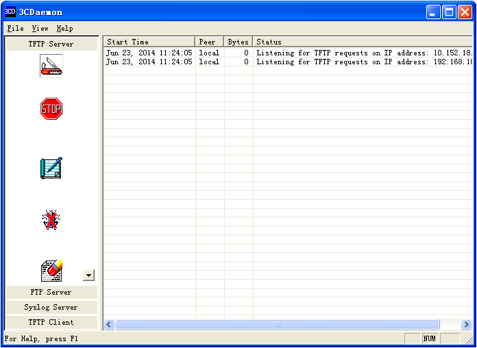
# Start the TFTP server and specify a working directory. This example uses the 3CDaemon TFTP server. (Details not shown.)
Figure 2 Configuring the TFTP server
2. Upgrade the device:
# Assign an IP address to M-GigabitEthernet 0/0/0. Make sure the device can reach the TFTP server.
<Device> system-view
System View: return to User View with Ctrl+Z.
[Device] interface m-gigabitethernet 0/0/0
[Device-M-GigabitEthernet0/0/0] ip address 192.168.100.66 255.255.255.0
[Device-M-GigabitEthernet0/0/0] quit
[Device] quit
# Verify that the device can ping the TFTP server.
<Device> ping 192.168.100.14
Ping 192.168.100.14 (192.168.100.14): 56 data bytes, press CTRL_C to break
56 bytes from 192.168.100.14: icmp_seq=0 ttl=64 time=10.701 ms
56 bytes from 192.168.100.14: icmp_seq=1 ttl=64 time=2.678 ms
56 bytes from 192.168.100.14: icmp_seq=2 ttl=64 time=2.282 ms
56 bytes from 192.168.100.14: icmp_seq=3 ttl=64 time=1.617 ms
56 bytes from 192.168.100.14: icmp_seq=4 ttl=64 time=1.701 ms
--- Ping statistics for 192.168.100.14 ---
5 packet(s) transmitted, 5 packet(s) received, 0.0% packet loss
round-trip min/avg/max/std-dev = 1.617/3.796/10.701/3.474 ms
# Save the configuration.
<Device> save
The current configuration will be written to the device. Are you sure? [Y/N]:y
Please input the file name(*.cfg)[flash:/startup.cfg]
(To leave the existing filename unchanged, press the enter key):
flash:/startup.cfg exists, overwrite? [Y/N]:y
Validating file. Please wait...
Saved the current configuration to mainboard device successfully.
# Use TFTP to download the upgrade file switch.ipe from the TFTP server to the root directory of the storage medium on the device.
<Device> tftp 192.168.100.14 get switch.ipe
Press CTRL+C to abort.
% Total % Received % Xferd Average Speed Time Time Time Current
Dload Upload Total Spent Left Speed
100 58.7M 100 58.7M 0 0 1193k 0 0:00:50 0:00:50 --:--:-- 1127k
# Specify switch.ipe as the main startup image file.
<Device> boot-loader file flash:/switch.ipe slot 1 main
Verifying the file flash:/switch.ipe on slot 1.....Done.
Images in IPE:
boot.bin
system.bin
This command will set the main startup software images. Continue? [Y/N]:y
Add images to slot 1.
Decompressing file switch.bin to flash:/boot.bin.........Done.
Decompressing file switch.bin to flash:/system.bin...........................Done.
The images that have passed all examinations will be used as the main startup software images at the next reboot on slot 1.
# Reboot the device.
<Device> reboot
Verifying the configuration
# Verify that the software has been upgraded.
<Device> display version
H3C Comware Software, Version 7.1.075, Release 3606
Copyright (c) 2004-2020 New H3C Technologies Co., Ltd. All rights reserved.
H3C S12500R uptime is 0 weeks, 0 days, 0 hours, 19 minutes
Last reboot reason : Cold reboot
MPU(M) Slot 1:
Uptime is 1 week,5 days,0 hours,48 minutes
H3C S12500R MPU(M) with 1 XLP208 Processor(s)
---- More ----
# Display the current software images and startup software images.
<Device> display boot-loader
Software images on slot 1:
Current software images:
flash:/boot.bin
flash:/system.bin
Main startup software images:
flash:/boot.bin
flash:/system.bin
Backup startup software images:
None
Configuration files
#
interface M-GigabitEthernet0/0/0
ip address 192.168.100.66 255.255.255.0
#
Example: Using the switch as an FTP client to upgrade software
Network configuration
As shown in Figure 3, use FTP to download a software upgrade file from an FTP server to upgrade the device.

Software versions used
This configuration example was created and verified on Release 3606.
Procedures
1. Configure the FTP server:
# Assign the IP address 192.168.100.14/24 to the FTP server. (Details not shown.)
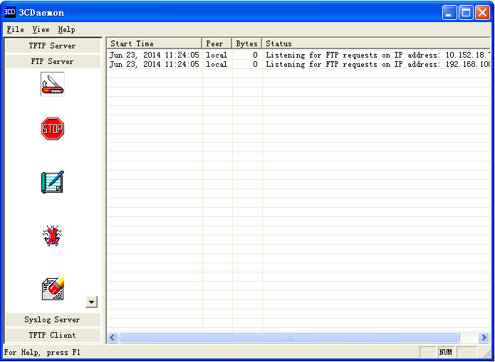
# Start the FTP server and specify a working directory. This example uses the 3CDaemon FTP server. (Details not shown.)
# Add a local user account. (Details not shown.)
# Set the username to 123456 and the password to 123456 for the user account.
Figure 4 Configuring the FTP server
2. Upgrade the device:
# Assign an IP address to M-GigabitEthernet 0/0/0. Make sure the device can reach the FTP server.
<Device> system-view
System View: return to User View with Ctrl+Z.
[Device] interface m-gigabitethernet 0/0/0
[Device-M-GigabitEthernet0/0/0] ip address 192.168.100.66 255.255.255.0
[Device-M-GigabitEthernet0/0/0] quit
[Device] quit
# Verify that the device can ping the FTP server.
<Device> ping 192.168.100.14
Ping 192.168.100.14 (192.168.100.14): 56 data bytes, press CTRL_C to break
56 bytes from 192.168.100.14: icmp_seq=0 ttl=64 time=10.701 ms
56 bytes from 192.168.100.14: icmp_seq=1 ttl=64 time=2.678 ms
56 bytes from 192.168.100.14: icmp_seq=2 ttl=64 time=2.282 ms
56 bytes from 192.168.100.14: icmp_seq=3 ttl=64 time=1.617 ms
56 bytes from 192.168.100.14: icmp_seq=4 ttl=64 time=1.701 ms
--- Ping statistics for 192.168.100.14 ---
5 packet(s) transmitted, 5 packet(s) received, 0.0% packet loss
round-trip min/avg/max/std-dev = 1.617/3.796/10.701/3.474 ms
# Save the configuration.
<Device> save
The current configuration will be written to the device. Are you sure? [Y/N]:y
Please input the file name(*.cfg)[flash:/startup.cfg]
(To leave the existing filename unchanged, press the enter key):
flash:/startup.cfg exists, overwrite? [Y/N]:y
Validating file. Please wait...
Saved the current configuration to mainboard device successfully.
# Use the username 123456 and the password 123456 to log in to the FTP server.
<Device> ftp 192.168.100.14
Connected to 192.168.100.14 (192.168.100.14).
220 3Com 3CDaemon FTP Server Version 2.0
User (192.168.100.14:(none)): 123456
331 User name ok, need password
Password:
230 User logged in
Remote system type is UNIX.
Using binary mode to transfer files.
# Use FTP to download the upgrade file switch.ipe from the FTP server to the root directory of the storage medium on the device.
ftp> get switch.ipe
227 Entering passive mode (192,168,100,14,8,86)
125 Using existing data connection
226 Closing data connection; File transfer successful.
50445056 bytes received in 53.6 seconds (1.25 Mbyte/s)
ftp> quit
# Specify switch.ipe as the main startup image file.
<Device> boot-loader file flash:/switch.ipe slot 1 main
Verifying the file flash:/switch.ipe on slot 1.....Done.
Images in IPE:
boot.bin
system.bin
This command will set the main startup software images. Continue? [Y/N]:y
Add images to slot 1.
Decompressing file switch.bin to flash:/boot.bin.........Done.
Decompressing file switch.bin to flash:/system.bin.................................Done.
The images that have passed all examinations will be used as the main startup software images at the next reboot on on slot 1.
# Reboot the switch.
<Device> reboot
Verifying the configuration
# Verify that the software has been upgraded.
<Device> display version
H3C Comware Software, Version 7.1.075, Release 3606
Copyright (c) 2004-2020 New H3C Technologies Co., Ltd. All rights reserved.
H3C S12500R uptime is 0 weeks, 0 days, 0 hours, 19 minutes
Last reboot reason : Cold reboot
MPU(M) Slot 1:
Uptime is 1 week,5 days,1 hours,32 minutes
H3C S12500R MPU(M) with 1 XLP208 Processor(s)
---- More ----
# Display the current software images and startup software images.
<Device> display boot-loader
Software images on slot 1:
Current software images:
flash:/boot.bin
flash:/system.bin
Main startup software images:
flash:/boot.bin
flash:/system.bin
Backup startup software images:
None
Configuration files
#
interface M-GigabitEthernet0/0/0
ip address 192.168.100.66 255.255.255.0
#
Example: Using the switch as an FTP server to upgrade software
Network configuration
As shown in Figure 5:
· Enable the FTP server on the device.
· Use FTP to upload a software upgrade file from an FTP client to upgrade the device.

Software versions used
This configuration example was created and verified on Release 3606.
Analysis
To use the device as an FTP server, you must create a local user account on the device to provide FTP service.
Restrictions and guidelines
You must set the file transfer mode to binary for FTP to transfer files correctly.
Procedures
1. Configure the FTP server:
# Assign an IP address to M-GigabitEthernet 0/0/0.
<Device> system-view
System View: return to User View with Ctrl+Z.
[Device] interface m-gigabitethernet 0/0/0
[Device-M-GigabitEthernet0/0/0] ip address 192.168.100.66 255.255.255.0
[Device-M-GigabitEthernet0/0/0] quit
# Add a local user account. Set the username to abc and the password to 123456.
[Device] local-user abc
[Device-luser-abc] password simple 123456
# Assign the network-admin user role to the user account.
[Device-luser-abc] authorization-attribute user-role network-admin
# Remove the default network-operator user role.
[Device-luser-abc] undo authorization-attribute user-role network-operator
# Assign FTP service to the user account.
[Device-luser-abc] service-type ftp
[Device-luser-abc] quit
# Enable the FTP server.
[Device] ftp server enable
[Device] quit
# Save the configuration.
<Device> save
The current configuration will be written to the device. Are you sure? [Y/N]:y
Please input the file name(*.cfg)[flash:/startup.cfg]
(To leave the existing filename unchanged, press the enter key):
flash:/startup.cfg exists, overwrite? [Y/N]:y
Validating file. Please wait...
Saved the current configuration to mainboard device successfully.
2. Configure the FTP client:
# Assign the IP address 192.168.100.14/24 to the FTP client. Make sure the FTP client can reach the device. (Details not shown.)
# Use the username abc and the password 123456 to log in to the FTP server.
C:\Documents and Settings\Administrator> ftp 192.168.100.66
Connected to 192.168.100.66.
220 FTP service ready.
User (192.168.100.66:(none)): abc
331 Password required for abc.
Password:
230 User logged in.
# Access the directory that contains the upgrade file.
ftp> lcd E:\
Local directory now E:\
# Set the file transfer mode to binary.
ftp> binary
200 TYPE is now 8-bit binary
# Transfer the upgrade file switch.ipe to the root directory of the storage medium on the FTP server.
ftp> put switch.ipe
200 PORT command successful
150 Connecting to port 2903
226 File successfully transferred
ftp: 50445056 sent in 1.05Seconds 67282.77Kbytes/sec.
# Verify that the image file is saved on the FTP server.
ftp> ls switch.ipe
200 PORT command successful
150 Connecting to port 3391
switch.ipe
226 1 matches total
ftp: 24 bytes received in 0.00Seconds 24000.00Kbytes/sec.
# Close the FTP connection.
ftp> bye
3. Upgrade the device:
# Specify switch.ipe as the main startup image file.
<Switch> boot-loader file flash:/switch.ipe slot 1 main
Verifying the IPE file and the images.....Done.
Verifying the file flash:/switch.ipe on slot 1.....Done.
Images in IPE:
boot.bin
system.bin
This command will set the main startup software images. Continue? [Y/N]:y
Add images to slot 1.
Decompressing file switch.bin to flash:/boot.bin.........Done.
Decompressing file switch.bin to flash:/system.bin.................................Done.
The images that have passed all examinations will be used as the main startup software images at the next reboot on slot 1.
# Reboot the device.
<Device> reboot
Verifying the configuration
# Verify that the software has been upgraded.
<Device> display version
H3C Comware Software, Version 7.1.070,R3606
Copyright (c) 2004-2019 New H3C Technologies Co., Ltd. All rights reserved.
H3C S12500R uptime is 0 weeks, 0 days, 0 hours, 19 minutes
Last reboot reason : User reboot
MPU(M) Slot 1:
Uptime is 1 week,5 days,1 hours,32 minutes
H3C S12500R MPU(M) with 1 XLP208 Processor(s)
---- More ----
# Display the current software images and startup software images.
<Device> display boot-loader
Software images on slot 1:
Current software images:
flash:/boot.bin
flash:/system.bin
Main startup software images:
flash:/boot.bin
flash:/system.bin
Backup startup software images:
None
Configuration files
#
interface M-GigabitEthernet0/0/0
ip address 192.168.100.66 255.255.255.0
#
local-user abc class manage
password hash $h$6$YMVbbwFL/vviWcQu$+CuTbYCehNZtZo5RCXiadpYbXYWa2omt5TUtEh3UPCg3fZjxYCp5WzbuE2GoowVi2YA/BK+mnSZJZqi5jRDuCg==
service-type ftp
authorization-attribute user-role network-admin
#
ftp server enable
#
Related documentation
· H3C S12500R Switch Router Series Fundamentals Command Reference-R3606
· H3C S12500R Switch Router Series Fundamentals Configuration Guide-R3606