- Table of Contents
-
- H3C S12500R Ethernet Switch Router Series Config Examples-6W101
- 01-Login Management Configuration Examples
- 02-RBAC Configuration Examples
- 03-Software Upgrade Examples
- 04-Ethernet Link Aggregation Configuration Examples
- 05-Port Isolation Configuration Examples
- 06-Spanning Tree Configuration Examples
- 07-VLAN Configuration Examples
- 08-VLAN Tagging Configuration Examples
- 09-DHCP Snooping Configuration Examples
- 10-Cross-Subnet Dynamic IP Address Allocation Configuration Examples
- 11-IPv6 over IPv4 Tunneling with OSPFv3 Configuration Examples
- 12-GRE Tunnel Configuration Examples
- 13-GRE with OSPF Configuration Examples
- 14-OSPF Configuration Examples
- 15-IS-IS Configuration Examples
- 16-BGP Configuration Examples
- 17-Policy-Based Routing Configuration Examples
- 18-OSPFv3 Configuration Examples
- 19-IPv6 IS-IS Configuration Examples
- 20-Routing Policy Configuration Examples
- 21-IGMP Snooping Configuration Examples
- 22-IGMP Configuration Examples
- 23-MLD Snooping Configuration Examples
- 24-Basic MPLS Configuration Examples
- 25-MPLS L3VPN Configuration Examples
- 26-ACL Configuration Examples
- 27-Control Plane-Based QoS Policy Configuration Examples
- 28-Traffic Policing Configuration Examples
- 29-GTS and Rate Limiting Configuration Examples
- 30-Priority Mapping and Queue Scheduling Configuration Examples
- 31-Traffic Filtering Configuration Examples
- 32-AAA Configuration Examples
- 33-SSH Configuration Examples
- 34-IP Source Guard Configuration Examples
- 35-Ethernet OAM Configuration Examples
- 36-CFD Configuration Examples
- 37-DLDP Configuration Examples
- 38-VRRP Configuration Examples
- 39-BFD Configuration Examples
- 40-NTP Configuration Examples
- 41-SNMP Configuration Examples
- 42-NQA Configuration Examples
- 43-Mirroring Configuration Examples
- 44-sFlow Configuration Examples
- 45-OpenFlow Configuration Examples
- 46-MAC Address Table Configuration Examples
- 47-Static Multicast MAC Address Entry Configuration Examples
- 48-IP Unnumbered Configuration Examples
- 49-Congestion Avoidance and Queue Scheduling Configuration Examples
- 50-Attack Protection Configuration Examples
- 51-Smart Link Configuration Examples
- 52-RRPP Configuration Examples
- 53-BGP Route Selection Configuration Examples
- 54-IS-IS Route Summarization Configuration Examples
- 55-MPLS OAM Configuration Examples
- 56-MPLS TE Configuration Examples
- 57-VXLAN Configuration Examples
- 58-NetStream Configuration Examples
- 59-EVPN-DCI over an MPLS L3VPN Network Configuration Examples
- 60-PTP Configuration Examples
- 61-S-MLAG Configuration Examples
- 62-MPLS SR Configuration Examples
- 63-Puppet Configuration Examples
- 64-Configuration Example of Using Ethernet OAM to Monitor ERPS Ring Link Performance
- 65-GRE Tunneling Between DHCP Relay and DHCP Server Configuration Examples
- 66-Loop Detection Configuration Examples
- 67-MPLS L3VPN+VRRP Configuration Examples
- 68-MSTP and VRRP Load Balancing Configuration Examples
- 69-Routing Policy for VPN Access Control Configuration Examples
- 70-Switch and Firewall Connection Configuration Examples for External Network Access
- 71-Switch and Router Connection Configuration Examples for External Network Access
- 72-VRRP Network Multicast Data Transmission Configuration Examples
- Related Documents
-
| Title | Size | Download |
|---|---|---|
| 68-MSTP and VRRP Load Balancing Configuration Examples | 119.19 KB |
|
|
|
H3C S12500R Switch Router Series |
|
MSTP and VRRP Load Balancing Configuration Examples |
|
|
Copyright © 2024 New H3C Technologies Co., Ltd. All rights reserved.
No part of this manual may be reproduced or transmitted in any form or by any means without prior written consent of New H3C Technologies Co., Ltd.
Except for the trademarks of New H3C Technologies Co., Ltd., any trademarks that may be mentioned in this document are the property of their respective owners.
The information in this document is subject to change without notice.
Example: Configuring MSTP and VRRP load balancing
Configuring the Layer 2 network
Configuring the Layer 3 network
Introduction
The following information describes the Multiple Spanning Tree Protocol (MSTP) and Virtual Router Redundancy Protocol (VRRP) load balancing configuration.
Prerequisites
The configuration examples were created and verified in a lab environment, and all the devices were started with the factory default configuration. When you are working on a live network, make sure you understand the potential impact of every command on your network.
The following information is provided based on the assumption that you have basic knowledge of MSTP and VRRP.
Example: Configuring MSTP and VRRP load balancing
Network configuration
As shown in Figure 1, the access layer device is dual homed to the core layer devices. For network availability, make sure the following requirements are met:
· Deploy link redundancy in the network, so that the upstream traffic of Device C can be load-balanced between two uplinks. Traffic from Host A is sent to Device A, and traffic from Host B is sent to Device B.
· When one uplink is disconnected, all traffic can switch over to another uplink for forwarding.
· Avoid loops in the network caused by redundant deployment.
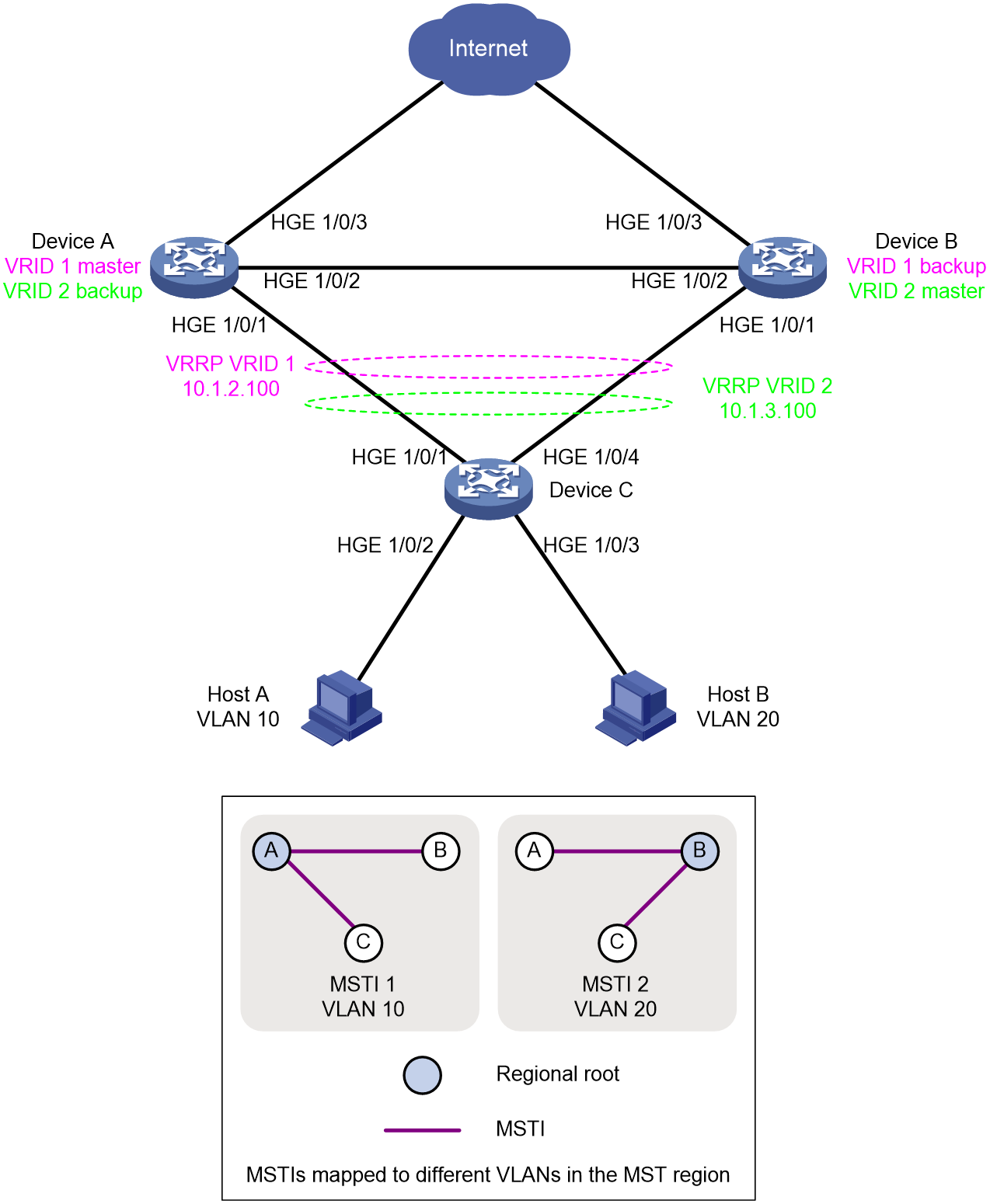
Table 1 shows the IP address plan in this example.
|
Configuration item |
Remarks |
|
|
Device A |
VLAN-interface 10 |
Assign HGE 1/0/1 and HGE 1/0/2 to VLAN 10, and configure the IP address for VLAN-interface 10 as 10.1.10.1/24. |
|
VLAN-interface 20 |
Assign HGE 1/0/1 and HGE 1/0/2 to VLAN 20, and configure the IP address for VLAN-interface 20 as 10.1.20.1/24. |
|
|
VLAN-interface 30 |
Assign HGE 1/0/3 to VLAN 30, and configure the IP address for VLAN-interface 30 as 10.1.30.1/24. |
|
|
Device B |
VLAN-interface 10 |
Assign HGE 1/0/1 and HGE 1/0/2 to VLAN 10, and configure the IP address for VLAN-interface 10 as 10.1.10.2/24. |
|
VLAN-interface 20 |
Assign HGE 1/0/1 and HGE 1/0/2 to VLAN 20, and configure the IP address for VLAN-interface 20 as 10.1.20.2/24. |
|
|
VLAN-interface 30 |
Assign HGE 1/0/3 to VLAN 30, and configure the IP address for VLAN-interface 30 as 10.1.30.2/24. |
|
Analysis
· Deploy MSTP between Device A, Device B, and Device C to eliminate loops in the network. Configure spanning tree instances to generate different network topologies for VLAN 10 and VLAN 20.
· Deploy VRRP on Device A and Device B to achieve link redundancy backup and create multiple VRRP groups to achieve load sharing of Layer 3 traffic.
Software versions used
This configuration example was created and verified on Release 5210 or later versions of S12500R.
Restrictions and guidelines
In this configuration example, some physical interfaces are required to operate in Layer 2 mode. To change the link mode of a physical interface to Layer 2, execute the port link-mode bridge command.
By default, interfaces on the device are disabled (in ADM or Administratively Down state). To have an interface operate, you must use the undo shutdown command to enable that interface.
Make sure the following settings are consistent on all members in a VRRP group.
· Number of virtual IP addresses.
· Virtual IP address of the VRRP group.
· Timers and authentication mode.
Make sure the reduced priority is lower than the priority of any other switches in the VRRP group, so that another switch can be elected as the master.
Do not configure the spanning tree feature together with the service loopback group, RRPP, Smart Link, and L2PT features, because such features are mutually exclusive.
Procedures
Configuring the Layer 2 network
1. Configure Device A:
# Create VLAN 10 and VLAN 20. Configure HundredGigE 1/0/1 and HundredGigE 1/0/2 as trunk ports, and assign them to VLAN 10 and VLAN 20.
<DeviceA> system-view
[DeviceA] vlan 10 20
[DeviceA] interface range hundredgige 1/0/1 to hundredgige 1/0/2
[DeviceA-if-range] port link-type trunk
[DeviceA-if-range] port trunk permit vlan 10 20
[DeviceA-if-range] undo port trunk permit vlan 1
[DeviceA-if-range] quit
# Configure the MST region.
<DeviceA> system-view
[DeviceA] stp region-configuration
[DeviceA-mst-region] region-name reg
[DeviceA-mst-region] instance 1 vlan 10
[DeviceA-mst-region] instance 2 vlan 20
# Activate MST region configuration.
[DeviceA-mst-region] active region-configuration
[DeviceA-mst-region] quit
# Specify Device A as the root bridge of MSTI 1 and a secondary root bridge of MSTI 2.
[DeviceA] stp instance 1 root primary
[DeviceA] stp instance 2 root secondary
# Enable root guard on HundredGigE 1/0/1.
[DeviceA] interface hundredgige 1/0/1
[DeviceA-HundredGigE1/0/1] stp root-protection
# Configure the spanning tree device to operate in MSTP mode, and globally enable the spanning tree feature.
[DeviceA] stp mode mstp
[DeviceA] stp global enable
2. Configure Device B:
# Create VLAN 10 and VLAN 20. Configure HundredGigE 1/0/1 and HundredGigE 1/0/2 as trunk ports, and assign them to VLAN 10 and VLAN 20.
<DeviceB> system-view
[DeviceB] vlan 10 20
[DeviceB] interface range hundredgige 1/0/1 to hundredgige 1/0/2
[DeviceB-if-range] port link-type trunk
[DeviceB-if-range] port trunk permit vlan 10 20
[DeviceB-if-range] undo port trunk permit vlan 1
[DeviceB-if-range] quit
# Configure the MST region.
<DeviceB> system-view
[DeviceB] stp region-configuration
[DeviceB-mst-region] region-name reg
[DeviceB-mst-region] instance 1 vlan 10
[DeviceB-mst-region] instance 2 vlan 20
# Activate MST region configuration.
[DeviceB-mst-region] active region-configuration
[DeviceB-mst-region] quit
# Specify Device B as the root bridge of MSTI 2 and a secondary root bridge of MSTI 1.
[DeviceB] stp instance 2 root primary
[DeviceB] stp instance 1 root secondary
# Enable root guard on HundredGigE 1/0/1.
[DeviceB] interface hundredgige 1/0/1
[DeviceB-HundredGigE1/0/1] stp root-protection
# Configure the spanning tree device to operate in MSTP mode, and globally enable the spanning tree feature.
[DeviceB] stp mode mstp
[DeviceB] stp global enable
3. Configure Device C:
# Create VLAN 10 and VLAN 20. Configure HundredGigE 1/0/1 and HundredGigE 1/0/4 as trunk ports, and assign them to VLAN 10 and VLAN 20.
<DeviceC> system-view
[DeviceC] vlan 10 20
[DeviceC] interface range hundredgige 1/0/1 hundredgige 1/0/4
[DeviceC-if-range] port link-type trunk
[DeviceC-if-range] port trunk permit vlan 10 20
[DeviceC-if-range] undo port trunk permit vlan 1
[DeviceC-if-range] quit
# Configure the MST region.
<DeviceC> system-view
[DeviceC] stp region-configuration
[DeviceC-mst-region] region-name reg
[DeviceC-mst-region] instance 1 vlan 10
[DeviceC-mst-region] instance 2 vlan 20
# Activate MST region configuration.
[DeviceC-mst-region] active region-configuration
[DeviceC-mst-region] quit
# Specify HundredGigE 1/0/2 as an access port and assign it to VLAN 10.
[DeviceC] interface hundredgige 1/0/2
[DeviceC-HundredGigE1/0/2] port link-type access
[DeviceC-HundredGigE1/0/2] port access vlan 10
[DeviceC-HundredGigE1/0/2] quit
# Specify HundredGigE 1/0/3 as an access port and assign it to VLAN 20.
[DeviceC] interface hundredgige 1/0/3
[DeviceC-HundredGigE1/0/3] port link-type access
[DeviceC-HundredGigE1/0/3] port access vlan 20
[DeviceC-HundredGigE1/0/3] quit
# Configure HundredGigE 1/0/2 and HundredGigE 1/0/3 as edge ports, enable BPDU guard on them.
[DeviceC] interface range hundredgige 1/0/2 to hundredgige 1/0/3
[DeviceC-if-range] stp edged-port
[DeviceC-if-range] stp port bpdu-protection enable
[DeviceC-if-range] quit
# Configure the spanning tree device to operate in MSTP mode, and globally enable the spanning tree feature.
[DeviceC] stp mode mstp
[DeviceC] stp global enable
Configuring the Layer 3 network
1. Configure Device A:
# Create VLAN 30. Specify HundredGigE 1/0/3 as a trunk port and assign it to VLAN 30.
<DeviceA> system-view
[DeviceA] vlan 30
[DeviceA-vlan30] quit
[DeviceA] interface range hundredgige 1/0/3
[DeviceA-HundredGigE1/0/3] port link-type trunk
[DeviceA-HundredGigE1/0/3] port trunk permit vlan 30
[DeviceA-HundredGigE1/0/3] undo port trunk permit vlan 1
[DeviceA-HundredGigE1/0/3] quit
# Create VLAN-interface 10, and configure its IP address.
[DeviceA] interface vlan-interface 10
[DeviceA-Vlan-interface10] ip address 10.1.10.1 24
# Create VLAN-interface 20, and configure its IP address.
[DeviceA] interface vlan-interface 20
[DeviceA-Vlan-interface20] ip address 10.1.20.1 24
# Create VLAN-interface 30, and configure its IP address.
[DeviceA] interface vlan-interface 30
[DeviceA-Vlan-interface30] ip address 10.1.30.1 24
# Create VRRP group 1, and set its virtual IP address to 10.1.10.100. Configure the priority of Device A in VRRP group 1 as 120 (for Device A to become the master), enable the preemptive mode for Device A, and set the preemption delay to 20 seconds.
[DeviceA] interface vlan-interface 10
[DeviceA-Vlan-interface10] vrrp vrid 1 virtual-ip 10.1.10.100
[DeviceA-Vlan-interface10] vrrp vrid 1 priority 120
[DeviceA-Vlan-interface10] vrrp vrid 1 preempt-mode timer delay 20
[DeviceA-Vlan-interface10] quit
# Create VRRP group 2, and set its virtual IP address to 10.1.20.100.
[DeviceA] interface vlan-interface 20
[DeviceA-Vlan-interface20] vrrp vrid 2 virtual-ip 10.1.20.100
[DeviceA-Vlan-interface20] quit
2. Configure Device B:
# Create VLAN 30. Specify HundredGigE 1/0/3 as a trunk port and assign it to VLAN 30.
<DeviceB> system-view
[DeviceB] vlan 30
[DeviceB-vlan30] quit
[DeviceB] interface range hundredgige 1/0/3
[DeviceB-HundredGigE1/0/3] port link-type trunk
[DeviceB-HundredGigE1/0/3] port trunk permit vlan 30
[DeviceB-HundredGigE1/0/3] undo port trunk permit vlan 1
[DeviceB-HundredGigE1/0/3] quit
# Create VLAN-interface 10, and configure its IP address.
[DeviceB] interface vlan-interface 10
[DeviceB-Vlan-interface10] ip address 10.1.10.2 24
# Create VLAN-interface 20, and configure its IP address.
[DeviceB] interface vlan-interface 20
[DeviceB-Vlan-interface20] ip address 10.1.20.2 24
# Create VLAN-interface 30, and configure its IP address.
[DeviceB] interface vlan-interface 30
[DeviceB-Vlan-interface30] ip address 10.1.30.2 24
# Create VRRP group 2, and set its virtual IP address to 10.1.20.100. Configure the priority of Device B in VRRP group 2 as 120 (for Device B to become the master), enable the preemptive mode for Device B, and set the preemption delay to 20 seconds.
[DeviceB] interface vlan-interface 20
[DeviceB-Vlan-interface20] vrrp vrid 2 virtual-ip 10.1.20.100
[DeviceB-Vlan-interface20] vrrp vrid 2 priority 120
[DeviceB-Vlan-interface20] vrrp vrid 2 preempt-mode timer delay 20
[DeviceB-Vlan-interface20] quit
# Create VRRP group 1, and set its virtual IP address to 10.1.10.100.
[DeviceB] interface vlan-interface 10
[DeviceB-Vlan-interface10] vrrp vrid 1 virtual-ip 10.1.10.100
[DeviceB-Vlan-interface10] quit
3. On Host A, configure the default gateway address as 10.1.10.100. (Details not shown.)
4. On Host B, configure the default gateway address as 10.1.20.100. (Details not shown.)
Verifying the configuration
1. Display root bridge information for all MSTIs on Device A. You can see that Device A is the root bridge of MSTI 1 and Device B is the root bridge of MSTI 2.
<DeviceA> display stp root
MST ID Root Bridge ID ExtPathCost IntPathCost Root Port
0 32768.7e23-3be5-0100 0 0
1 0.7e23-3be5-0100 0 0
2 0.7e23-45d4-0200 0 20 HGE1/0/2
2. Display brief spanning tree information on Device C. In MSTI 1, HundredGigE 1/0/4 is blocked, and traffic of VLAN 10 is forwarded through HundredGigE 1/0/1 to Device A. In MSTI 2, HundredGigE 1/0/1 is blocked, and traffic of VLAN 20 is forwarded through HundredGigE 1/0/4 to Device B. Traffic load balancing is achieved.
<DeviceC> display stp brief
MST ID Port Role STP State Protection
0 HundredGigE1/0/1 ROOT FORWARDING NONE
0 HundredGigE1/0/2 DESI FORWARDING NONE
0 HundredGigE1/0/3 DESI FORWARDING NONE
0 HundredGigE1/0/4 ALTE DISCARDING NONE
1 HundredGigE1/0/1 ROOT FORWARDING NONE
1 HundredGigE1/0/2 DESI FORWARDING NONE
1 HundredGigE1/0/4 ALTE DISCARDING NONE
2 HundredGigE1/0/1 ALTE DISCARDING NONE
2 HundredGigE1/0/3 DESI FORWARDING NONE
2 HundredGigE1/0/4 ROOT FORWARDING NONE
3. Display detailed VRRP group information Device A. You can see that Device A is the master in VRRP group 1 and backup in VRRP group 2. Device B is the backup in VRRP group 1 and master in VRRP group 2.
<DeviceA> display vrrp verbose
IPv4 Virtual Router Information:
Running mode : Standard
Total number of virtual routers : 2
Interface Vlan-interface10
VRID : 1 Adver Timer : 100
Admin Status : Up State : Master
Config Pri : 120 Running Pri : 120
Preempt Mode : Yes Delay Time : 20
Auth Type : Not supported
Version : 3
Virtual IP : 10.1.10.100
Virtual MAC : 0000-5e00-0101
Master IP : 10.1.10.1
First connection : 2023/04/22 16:46:04.531
Last status change : 2023/04/22 16:46:04.531
Interface Vlan-interface20
VRID : 2 Adver Timer : 100
Admin Status : Up State : Backup
Config Pri : 100 Running Pri : 100
Preempt Mode : Yes Delay Time : 0
Become Master : 0ms left
Auth Type : Not supported
Version : 3
Virtual IP : 10.1.20.100
Virtual MAC : 0000-5e00-0102
Master IP : 10.1.20.2
First connection : 2023/04/22 16:47:50.061
Last status change : 2023/04/22 16:47:50.061
4. Verify that Host A can ping the 10.1.10.100 (virtual IP address of the gateway) and Host B can ping 10.1.20.100 (virtual IP address of the gateway).
Configuration files
· Device A:
#
vlan 1
#
vlan 10
#
vlan 20
#
vlan 30
#
stp region-configuration
region-name reg
instance 1 vlan 10
instance 2 vlan 20
active region-configuration
#
stp instance 1 root primary
stp instance 2 root secondary
stp global enable
#
interface Vlan-interface10
ip address 10.1.10.1 255.255.255.0
vrrp vrid 1 virtual-ip 10.1.10.100
vrrp vrid 1 priority 120
vrrp vrid 1 preempt-mode delay 20
#
interface Vlan-interface20
ip address 10.1.20.1 255.255.255.0
vrrp vrid 2 virtual-ip 10.1.20.100
#
interface Vlan-interface30
ip address 10.1.30.1 255.255.255.0
#
interface HundredGigE1/0/1
port link-mode bridge
port link-type trunk
undo port trunk permit vlan 1
port trunk permit vlan 10 20
stp root-protection
#
interface HundredGigE1/0/2
port link-mode bridge
port link-type trunk
undo port trunk permit vlan 1
port trunk permit vlan 10 20
#
interface HundredGigE1/0/3
port link-mode bridge
port link-type trunk
undo port trunk permit vlan 1
port trunk permit vlan 30
#
return
· Device B:
#
vlan 1
#
vlan 10
#
vlan 20
#
vlan 30
#
stp region-configuration
region-name reg
instance 1 vlan 10
instance 2 vlan 20
active region-configuration
#
stp instance 1 root secondary
stp instance 2 root primary
stp global enable
#
interface Vlan-interface10
ip address 10.1.10.2 255.255.255.0
vrrp vrid 1 virtual-ip 10.1.10.100
#
interface Vlan-interface20
ip address 10.1.20.2 255.255.255.0
vrrp vrid 2 virtual-ip 10.1.20.100
vrrp vrid 2 priority 120
vrrp vrid 2 preempt-mode delay 20
#
interface HundredGigE1/0/1
port link-mode bridge
port link-type trunk
undo port trunk permit vlan 1
port trunk permit vlan 10 20
stp root-protection
#
interface HundredGigE1/0/2
port link-mode bridge
port link-type trunk
undo port trunk permit vlan 1
port trunk permit vlan 10 20
#
interface HundredGigE1/0/3
port link-mode bridge
port link-type trunk
undo port trunk permit vlan 1
port trunk permit vlan 30
#
return
· Device C:
#
vlan 1
#
vlan 10
#
vlan 20
#
stp region-configuration
region-name reg
instance 1 vlan 10
instance 2 vlan 20
active region-configuration
#
stp global enable
#
interface HundredGigE1/0/1
port link-mode bridge
port link-type trunk
undo port trunk permit vlan 1
port trunk permit vlan 10 20
#
interface HundredGigE1/0/2
port link-mode bridge
port access vlan 10
stp edged-port
stp port bpdu-protection enable
#
interface HundredGigE1/0/3
port link-mode bridge
port access vlan 20
stp edged-port
stp port bpdu-protection enable
#
interface HundredGigE1/0/4
port link-mode bridge
port link-type trunk
undo port trunk permit vlan 1
port trunk permit vlan 10 20
#
return
Related documentation
· High Availability Configuration Guide in H3C S12500R Switch Router Series Configuration Guides-R52xx
· High Availability Command Reference in H3C S12500R Switch Router Series Command References-R52xx
· Layer 2—LAN Switching Configuration Guide in H3C S12500R Switch Router Series Configuration Guides-R52xx
· Layer 2—LAN Switching Command Reference in H3C S12500R Switch Router Series Command References-R52xx
· High Availability Configuration Guide in H3C S12500R-48Y8C&S12500R-48C6D Switch Router Configuration Guides-R52xx
· High Availability Command Reference in H3C S12500R-48Y8C&S12500R-48C6D Switch Router Command References-R52xx
· Layer 2—LAN Switching Configuration Guide in H3C S12500R-48Y8C&S12500R-48C6D Switch Router Configuration Guides-R52xx
· Layer 2—LAN Switching Command Reference in H3C S12500R-48Y8C&S12500R-48C6D Switch Router Command References-R52xx