- Table of Contents
-
- H3C S12500R Ethernet Switch Router Series Config Examples-6W101
- 01-Login Management Configuration Examples
- 02-RBAC Configuration Examples
- 03-Software Upgrade Examples
- 04-Ethernet Link Aggregation Configuration Examples
- 05-Port Isolation Configuration Examples
- 06-Spanning Tree Configuration Examples
- 07-VLAN Configuration Examples
- 08-VLAN Tagging Configuration Examples
- 09-DHCP Snooping Configuration Examples
- 10-Cross-Subnet Dynamic IP Address Allocation Configuration Examples
- 11-IPv6 over IPv4 Tunneling with OSPFv3 Configuration Examples
- 12-GRE Tunnel Configuration Examples
- 13-GRE with OSPF Configuration Examples
- 14-OSPF Configuration Examples
- 15-IS-IS Configuration Examples
- 16-BGP Configuration Examples
- 17-Policy-Based Routing Configuration Examples
- 18-OSPFv3 Configuration Examples
- 19-IPv6 IS-IS Configuration Examples
- 20-Routing Policy Configuration Examples
- 21-IGMP Snooping Configuration Examples
- 22-IGMP Configuration Examples
- 23-MLD Snooping Configuration Examples
- 24-Basic MPLS Configuration Examples
- 25-MPLS L3VPN Configuration Examples
- 26-ACL Configuration Examples
- 27-Control Plane-Based QoS Policy Configuration Examples
- 28-Traffic Policing Configuration Examples
- 29-GTS and Rate Limiting Configuration Examples
- 30-Priority Mapping and Queue Scheduling Configuration Examples
- 31-Traffic Filtering Configuration Examples
- 32-AAA Configuration Examples
- 33-SSH Configuration Examples
- 34-IP Source Guard Configuration Examples
- 35-Ethernet OAM Configuration Examples
- 36-CFD Configuration Examples
- 37-DLDP Configuration Examples
- 38-VRRP Configuration Examples
- 39-BFD Configuration Examples
- 40-NTP Configuration Examples
- 41-SNMP Configuration Examples
- 42-NQA Configuration Examples
- 43-Mirroring Configuration Examples
- 44-sFlow Configuration Examples
- 45-OpenFlow Configuration Examples
- 46-MAC Address Table Configuration Examples
- 47-Static Multicast MAC Address Entry Configuration Examples
- 48-IP Unnumbered Configuration Examples
- 49-Congestion Avoidance and Queue Scheduling Configuration Examples
- 50-Attack Protection Configuration Examples
- 51-Smart Link Configuration Examples
- 52-RRPP Configuration Examples
- 53-BGP Route Selection Configuration Examples
- 54-IS-IS Route Summarization Configuration Examples
- 55-MPLS OAM Configuration Examples
- 56-MPLS TE Configuration Examples
- 57-VXLAN Configuration Examples
- 58-NetStream Configuration Examples
- 59-EVPN-DCI over an MPLS L3VPN Network Configuration Examples
- 60-PTP Configuration Examples
- 61-S-MLAG Configuration Examples
- 62-MPLS SR Configuration Examples
- 63-Puppet Configuration Examples
- 64-Configuration Example of Using Ethernet OAM to Monitor ERPS Ring Link Performance
- 65-GRE Tunneling Between DHCP Relay and DHCP Server Configuration Examples
- 66-Loop Detection Configuration Examples
- 67-MPLS L3VPN+VRRP Configuration Examples
- 68-MSTP and VRRP Load Balancing Configuration Examples
- 69-Routing Policy for VPN Access Control Configuration Examples
- 70-Switch and Firewall Connection Configuration Examples for External Network Access
- 71-Switch and Router Connection Configuration Examples for External Network Access
- 72-VRRP Network Multicast Data Transmission Configuration Examples
- Related Documents
-
| Title | Size | Download |
|---|---|---|
| 69-Routing Policy for VPN Access Control Configuration Examples | 205.59 KB |
|
|
|
H3C S12500R Switch Router Series |
|
Routing Policy for VPN Access Control Configuration Examples |
|
|
Copyright © 2024 New H3C Technologies Co., Ltd. All rights reserved.
No part of this manual may be reproduced or transmitted in any form or by any means without prior written consent of New H3C Technologies Co., Ltd.
Except for the trademarks of New H3C Technologies Co., Ltd., any trademarks that may be mentioned in this document are the property of their respective owners.
The information in this document is subject to change without notice.
Contents
Example: Using routing policies to control access among VPN users
Applicable hardware and software versions
Introduction
The following information provides a configuration example that uses routing policies to control access among VPN users.
This document is not restricted to specific software or hardware versions.
The configuration examples were created and verified in a lab environment, and all the devices were started with the factory default configuration. When you are working on a live network, make sure you understand the potential impact of every command on your network. If you have configured the devices before performing this configuration task, make sure that the existing configuration does not conflict with the configuration in the following example.
The following information is provided based on the assumption that you have basic knowledge of routing policy.
Restrictions and guidelines
By default, interfaces on the device are disabled (in ADM or Administratively Down state). To have an interface operate, you must use the undo shutdown command to enable that interface.
Some physical interfaces in this example must operate in bridge (Layer 2) mode. By default, the physical interfaces on the device operate in routed (Layer 3) mode. To change the link mode of a physical interface, use the port link-mode command.
Example: Using routing policies to control access among VPN users
Applicable hardware and software versions
The following matrix shows the hardware and software versions to which this configuration example is applicable:
|
Hardware |
Software version |
|
S12500R switch series |
Release 5210 and later |
Network configuration
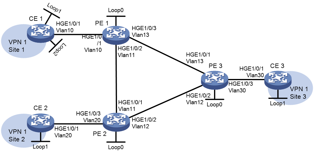
All sites within an enterprise network can access each other, belonging to the same VPN. To prevent a less secure site from accessing an important server deployed on a certain network, use routing policies to filter routes. In this way, you can limit the site’s access to the important server without affecting other inter-site VPN accesses.
As shown in Figure 1:
· CE 1, CE 2, and CE 3 belong to VPN 1.
· Two user networks 100.1.1.0/24 and 100.2.1.0/24 are connected to CE 1. An important server exists in network 100.2.1.0/24.
· Site 2 is connected to CE 2 and is less secure. It is not allowed to access network 100.2.1.0/24.
· The PEs use OSPF to communicate with each other, and use MP-IBGP to exchange VPNv4 routes.
· A PE and a CE use EBGP to exchange private network routes.
|
Device |
Interface |
IP address |
|
PE 1 |
Loop0 |
1.1.1.1/32 |
|
Vlan-int10 |
10.1.1.1/24 |
|
|
Vlan-int11 |
11.1.1.1/24 |
|
|
Vlan-int13 |
13.1.1.1/24 |
|
|
PE 2 |
Loop0 |
2.2.2.2/32 |
|
Vlan-int20 |
20.1.1.2/24 |
|
|
Vlan-int11 |
11.1.1.2/24 |
|
|
Vlan-int12 |
12.1.1.2/24 |
|
|
PE 3 |
Loop0 |
3.3.3.3/32 |
|
Vlan-int30 |
30.1.1.3/24 |
|
|
Vlan-int12 |
12.1.1.3/24 |
|
|
Vlan-int13 |
13.1.1.3/24 |
|
|
CE 1 |
Loop1 |
100.1.1.0/24 |
|
Loop2 |
100.2.1.0/24 |
|
|
Vlan-int10 |
10.1.1.10/24 |
|
|
CE 2 |
Loop1 |
200.1.1.0/24 |
|
Vlan-int20 |
20.1.1.20/24 |
|
|
CE 3 |
Loop1 |
103.1.1.0/24 |
|
Vlan-int30 |
30.1.1.30/24 |
Analysis
To control access among VPN users through routing policies in an MPLS L3VPN network, perform the following tasks:
· Configure EBGP between each PE and CE, so they can exchange private network routes. Redistribute direct routes into BGP on each CE.
· Configure OSPF on PE interfaces connected to the backbone network so that traffic can be routed to the public network.
· Establish MP-IBGP peer relationships between PEs, so they can exchange BGP VPNv4 routes.
· Perform the following operations to configure PE 2 to deny routes destined for network 100.2.1.0/24, thus disabling site 2 from accessing network 100.2.1.0/24:
¡ Configure a routing policy on PE 1. The routing policy adds RT attribute 2:2 to routes destined for network 100.2.1.0/24 when PE 1 advertises VPNv4 routes to PE 2.
¡ Configure a routing policy on PE 2 to deny routes carrying RT attribute 2:2.
Data plan
|
Item |
Value |
|
AS number for CE 1 |
65410 |
|
AS number for CE 2 |
65420 |
|
AS number for CE 3 |
65430 |
|
AS numbers for PE 1, PE 2, and PE 3 |
100 |
Procedures
Configuring PE 1
Assigning interfaces to VLANs
<Sysname> system-view
[Sysname] sysname PE1
[PE1] vlan 10
[PE1-vlan10] quit
[PE1] vlan 11
[PE1-vlan11] quit
[PE1] vlan 13
[PE1-vlan13] quit
[PE1] interface hundredgige 1/0/1
[PE1-HundredGigE1/0/1] port access vlan 10
[PE1-HundredGigE1/0/1] quit
[PE1] interface hundredgige 1/0/2
[PE1-HundredGigE1/0/2] port access vlan 11
[PE1-HundredGigE1/0/2] quit
[PE1] interface hundredgige 1/0/3
[PE1-HundredGigE1/0/3] port access vlan 13
[PE1-HundredGigE1/0/3] quit
Configuring IP addresses and unicast routing
# Configure IP addresses for the loopback interface and VLAN interfaces.
[PE1] interface loopback 0
[PE1-LoopBack0] ip address 1.1.1.1 255.255.255.255
[PE1-LoopBack0] quit
[PE1] interface vlan-interface 11
[PE1-Vlan-interface11] ip address 11.1.1.1 24
[PE1-Vlan-interface11] quit
[PE1] interface vlan-interface 13
[PE1-Vlan-interface13] ip address 13.1.1.1 24
[PE1-Vlan-interface13] quit
# Configure OSPF to achieve inter-network communication at the network layer.
[PE1] ospf
[PE1-ospf-1] area 0
[PE1-ospf-1-area-0.0.0.0] network 11.1.1.0 0.0.0.255
[PE1-ospf-1-area-0.0.0.0] network 13.1.1.0 0.0.0.255
[PE1-ospf-1-area-0.0.0.0] network 1.1.1.1 0.0.0.0
[PE1-ospf-1-area-0.0.0.0] quit
[PE1-ospf-1] quit
Configuring an MPLS LSR ID and enabling MPLS and MPLS LDP
[PE1] mpls lsr-id 1.1.1.1
[PE1] mpls ldp
[PE1-ldp] quit
[PE1] interface vlan-interface 11
[PE1-Vlan-interface11] mpls enable
[PE1-Vlan-interface11] mpls ldp enable
[PE1-Vlan-interface11] quit
[PE1] interface vlan-interface 13
[PE1-Vlan-interface13] mpls enable
[PE1-Vlan-interface13] mpls ldp enable
[PE1-Vlan-interface13] quit
Establishing MP-IBGP peer relationships between PEs for exchanging VPNv4 routes
[PE1] bgp 100
[PE1-bgp-default] peer 2.2.2.2 as-number 100
[PE1-bgp-default] peer 2.2.2.2 connect-interface loopback 0
[PE1-bgp-default] peer 3.3.3.3 as-number 100
[PE1-bgp-default] peer 3.3.3.3 connect-interface loopback 0
[PE1-bgp-default] address-family vpnv4
[PE1-bgp-default-vpnv4] peer 2.2.2.2 enable
[PE1-bgp-default-vpnv4] peer 3.3.3.3 enable
[PE1-bgp-default-vpnv4] quit
Configuring VPN instances
# Create VPN instance vpn1, and set its RD, import RT, and export RT.
[PE1] ip vpn-instance vpn1
[PE1-vpn-instance-vpn1] route-distinguisher 1:1
[PE1-vpn-instance-vpn1] vpn-target 1:1 import-extcommunity
[PE1-vpn-instance-vpn1] vpn-target 1:1 export-extcommunity
[PE1-vpn-instance-vpn1] quit
# Bind VLAN-interface 10 to VPN instance vpn1, and configure an IP address for the interface.
[PE1] interface vlan-interface 10
[PE1-Vlan-interface10] ip binding vpn-instance vpn1
[PE1-Vlan-interface10] ip address 10.1.1.1 24
[PE1-Vlan-interface10] quit
Establishing an EBGP peer relationship between PE 1 and CE 1 for exchanging private network routes
[PE1] bgp 100
[PE1-bgp-default] ip vpn-instance vpn1
[PE1-bgp-default-vpn1] peer 10.1.1.10 as-number 65410
[PE1-bgp-default-vpn1] address-family ipv4 unicast
[PE1-bgp-default-ipv4-vpn1] peer 10.1.1.10 enable
[PE1-bgp-default-ipv4-vpn1] quit
[PE1-bgp-default-vpn1] quit
Configuring a routing policy that adds RT attribute 2:2 to routes advertised to peer 2.2.2.2
# Create IP prefix list network1 to match network 100.2.1.0/24.
[PE1] ip prefix-list network1 index 10 permit 100.2.1.0 24
[PE1] ip prefix-list network1 index 20 deny 0.0.0.0 0
# Create routing policy addrt to add RT attribute 2:2 to routes destined for network 100.2.1.0/24.
[PE1] route-policy addrt permit node 10
[PE1-route-policy-addrt-10] if-match ip address prefix-list network1
[PE1-route-policy-addrt-10] apply extcommunity rt 2:2 additive
[PE1-route-policy-addrt-10] quit
[PE1] route-policy addrt permit node 20
[PE1-route-policy-addrt-20] quit
# In the BGP VPNv4 address family, apply routing policy addrt to routes advertised to peer 2.2.2.2.
[PE1] bgp 100
[PE1-bgp-default] address-family vpnv4
[PE1-bgp-default-vpnv4] peer 2.2.2.2 route-policy addrt export
[PE1-bgp-default-vpnv4] quit
[PE1-bgp-default] quit
Configuring PE 2
Assigning interfaces to VLANs
<Sysname> system-view
[Sysname] sysname PE2
[PE2] vlan 11
[PE2-vlan11] quit
[PE2] vlan 12
[PE2-vlan12] quit
[PE2] vlan 20
[PE2-vlan20] quit
[PE2] interface hundredgige 1/0/1
[PE2-HundredGigE1/0/1] port access vlan 11
[PE2-HundredGigE1/0/1] quit
[PE2] interface hundredgige 1/0/2
[PE2-HundredGigE1/0/2] port access vlan 12
[PE2-HundredGigE1/0/2] quit
[PE2] interface hundredgige 1/0/3
[PE2-HundredGigE1/0/3] port access vlan 20
[PE2-HundredGigE1/0/3] quit
Configuring IP addresses and unicast routing
# Configure IP addresses for the loopback interface and VLAN interfaces.
[PE2] interface loopback 0
[PE2-LoopBack0] ip address 2.2.2.2 255.255.255.255
[PE2-LoopBack0] quit
[PE2] interface vlan-interface 11
[PE2-Vlan-interface11] ip address 11.1.1.2 24
[PE2-Vlan-interface11] quit
[PE2] interface vlan-interface 12
[PE2-Vlan-interface12] ip address 12.1.1.2 24
[PE2-Vlan-interface12] quit
# Configure OSPF to achieve inter-network communication at the network layer.
[PE2] ospf
[PE2-ospf-1] area 0
[PE2-ospf-1-area-0.0.0.0] network 11.1.1.0 0.0.0.255
[PE2-ospf-1-area-0.0.0.0] network 12.1.1.0 0.0.0.255
[PE2-ospf-1-area-0.0.0.0] network 2.2.2.2 0.0.0.0
[PE2-ospf-1-area-0.0.0.0] quit
[PE2-ospf-1] quit
Configuring an MPLS LSR ID and enabling MPLS and MPLS LDP
[PE2] mpls lsr-id 2.2.2.2
[PE2] mpls ldp
[PE2-ldp] quit
[PE2] interface vlan-interface 11
[PE2-Vlan-interface11] mpls enable
[PE2-Vlan-interface11] mpls ldp enable
[PE2-Vlan-interface11] quit
[PE2] interface vlan-interface 12
[PE2-Vlan-interface12] mpls enable
[PE2-Vlan-interface12] mpls ldp enable
[PE2-Vlan-interface12] quit
Establishing MP-IBGP peer relationships between PEs for exchanging VPNv4 routes
[PE2] bgp 100
[PE2-bgp-default] peer 1.1.1.1 as-number 100
[PE2-bgp-default] peer 1.1.1.1 connect-interface loopback 0
[PE2-bgp-default] peer 3.3.3.3 as-number 100
[PE2-bgp-default] peer 3.3.3.3 connect-interface loopback 0
[PE2-bgp-default] address-family vpnv4
[PE2-bgp-default-vpnv4] peer 1.1.1.1 enable
[PE2-bgp-default-vpnv4] peer 3.3.3.3 enable
[PE2-bgp-default-vpnv4] quit
Configuring VPN instances
# Create VPN instance vpn1, and set its RD, import RT, and export RT.
[PE2] ip vpn-instance vpn1
[PE2-vpn-instance-vpn1] route-distinguisher 1:1
[PE2-vpn-instance-vpn1] vpn-target 1:1 import-extcommunity
[PE2-vpn-instance-vpn1] vpn-target 1:1 export-extcommunity
[PE2-vpn-instance-vpn1] quit
# Bind VLAN-interface 20 to VPN instance vpn1, and configure an IP address for the interface.
[PE2] interface vlan-interface 20
[PE2-Vlan-interface20] ip binding vpn-instance vpn1
[PE2-Vlan-interface20] ip address 20.1.1.2 24
[PE2-Vlan-interface20] quit
Establishing an EBGP peer relationship between PE 2 and CE 2 for exchanging private network routes
[PE2] bgp 100
[PE2-bgp-default] ip vpn-instance vpn1
[PE2-bgp-default-vpn1] peer 20.1.1.20 as-number 65420
[PE2-bgp-default-vpn1] address-family ipv4 unicast
[PE2-bgp-default-ipv4-vpn1] peer 20.1.1.20 enable
[PE2-bgp-default-ipv4-vpn1] quit
[PE2-bgp-default-vpn1] quit
Configuring a routing policy that denies routes with RT attribute 2:2
# Create extended community attribute list 1 to match RT attribute 2:2.
[PE2] ip extcommunity-list 1 index 1 permit rt 2:2
# Create routing policy checkrt that denies routes carrying RT attribute 2:2.
[PE2] route-policy checkrt deny node 10
[PE2-route-policy-checkrt-10] if-match extcommunity 1
[PE2-route-policy-checkrt-10] quit
[PE2] route-policy checkrt permit node 20
[PE2-route-policy-checkrt-20] quit
# In the BGP VPNv4 address family, apply routing policy checkrt to routes received from peer 1.1.1.1.
[PE2] bgp 100
[PE2-bgp-default] address-family vpnv4
[PE2-bgp-default-vpnv4] peer 1.1.1.1 route-policy checkrt import
[PE2-bgp-default-vpnv4] quit
[PE2-bgp-default] quit
Configuring PE 3
Assigning interfaces to VLANs
<Sysname> system-view
[Sysname] sysname PE3
[PE3] vlan 12
[PE3-vlan12] quit
[PE3] vlan 13
[PE3-vlan13] quit
[PE3] vlan 30
[PE3-vlan30] quit
[PE3] interface hundredgige 1/0/1
[PE3-HundredGigE1/0/1] port access vlan 13
[PE3-HundredGigE1/0/1] quit
[PE3] interface hundredgige 1/0/2
[PE3-HundredGigE1/0/2] port access vlan 12
[PE3-HundredGigE1/0/2] quit
[PE3] interface hundredgige 1/0/3
[PE3-HundredGigE1/0/3] port access vlan 30
[PE3-HundredGigE1/0/3] quit
Configuring IP addresses and unicast routing
# Configure IP addresses for the loopback interface and VLAN interfaces.
[PE3] interface loopback 0
[PE3-LoopBack0] ip address 3.3.3.3 255.255.255.255
[PE3-LoopBack0] quit
[PE3] interface vlan-interface 12
[PE3-Vlan-interface12] ip address 12.1.1.3 24
[PE3-Vlan-interface12] quit
[PE3] interface vlan-interface 13
[PE3-Vlan-interface13] ip address 13.1.1.3 24
[PE3-Vlan-interface13] quit
# Configure OSPF to achieve inter-network communication at the network layer.
[PE3] ospf
[PE3-ospf-1] area 0
[PE3-ospf-1-area-0.0.0.0] network 12.1.1.0 0.0.0.255
[PE3-ospf-1-area-0.0.0.0] network 13.1.1.0 0.0.0.255
[PE3-ospf-1-area-0.0.0.0] network 3.3.3.3 0.0.0.0
[PE3-ospf-1-area-0.0.0.0] quit
[PE3-ospf-1] quit
Configuring an MPLS LSR ID and enabling MPLS and MPLS LDP
[PE3] mpls lsr-id 3.3.3.3
[PE3] mpls ldp
[PE3-ldp] quit
[PE3] interface vlan-interface 12
[PE3-Vlan-interface12] mpls enable
[PE3-Vlan-interface12] mpls ldp enable
[PE3-Vlan-interface12] quit
[PE3] interface vlan-interface 13
[PE3-Vlan-interface13] mpls enable
[PE3-Vlan-interface13] mpls ldp enable
[PE3-Vlan-interface13] quit
Establishing MP-IBGP peer relationships between PEs for exchanging VPNv4 routes
[PE3] bgp 100
[PE3-bgp-default] peer 1.1.1.1 as-number 100
[PE3-bgp-default] peer 1.1.1.1 connect-interface loopback 0
[PE3-bgp-default] peer 2.2.2.2 as-number 100
[PE3-bgp-default] peer 2.2.2.2 connect-interface loopback 0
[PE3-bgp-default] address-family vpnv4
[PE3-bgp-default-vpnv4] peer 1.1.1.1 enable
[PE3-bgp-default-vpnv4] peer 2.2.2.2 enable
[PE3-bgp-default-vpnv4] quit
Configuring VPN instances
# Create VPN instance vpn1, and set its RD, import RT, and export RT.
[PE3] ip vpn-instance vpn1
[PE3-vpn-instance-vpn1] route-distinguisher 1:1
[PE3-vpn-instance-vpn1] vpn-target 1:1 import-extcommunity
[PE3-vpn-instance-vpn1] vpn-target 1:1 export-extcommunity
[PE3-vpn-instance-vpn1] quit
# Bind VLAN-interface 30 to VPN instance vpn1, and configure an IP address for the interface.
[PE3] interface vlan-interface 30
[PE3-Vlan-interface30] ip binding vpn-instance vpn1
[PE3-Vlan-interface30] ip address 30.1.1.3 24
[PE3-Vlan-interface30] quit
Establishing an EBGP peer relationship between PE 3 and CE 3 for exchanging private network routes
[PE3] bgp 100
[PE3-bgp-default] ip vpn-instance vpn1
[PE3-bgp-default-vpn1] peer 30.1.1.30 as-number 65430
[PE3-bgp-default-vpn1] address-family ipv4 unicast
[PE3-bgp-default-ipv4-vpn1] peer 30.1.1.30 enable
[PE3-bgp-default-ipv4-vpn1] quit
[PE3-bgp-default-vpn1] quit
Configuring CE 1
Assigning interfaces to VLANs
<Sysname> system-view
[Sysname] sysname CE1
[CE1] vlan 10
[CE1-vlan10] quit
[CE1] interface hundredgige 1/0/1
[CE1-HundredGigE1/0/1] port access vlan 10
[CE1-HundredGigE1/0/1] quit
Configuring IP addresses
# Configure IP addresses for the loopback interfaces and VLAN interface.
[CE1] interface vlan-interface 10
[CE1-Vlan-interface100] ip address 10.1.1.10 24
[CE1-Vlan-interface100] quit
[CE1] interface loopback 1
[CE1-LoopBack1] ip address 100.1.1.1 24
[CE1-LoopBack1] quit
[CE1] interface loopback 2
[CE1-LoopBack1] ip address 100.2.1.1 24
[CE1-LoopBack1] quit
Establishing an EBGP peer relationship between CE 1 and PE 1 for redistributing direct routes into BGP
[CE1] bgp 65410
[CE1-bgp-default] peer 10.1.1.1 as-number 100
[CE1-bgp-default] address-family ipv4 unicast
[CE1-bgp-default-ipv4] peer 10.1.1.1 enable
[CE1-bgp-default-ipv4] import-route direct
[CE1-bgp-default-ipv4] quit
[CE1-bgp-default] quit
Configuring CE 2
Assigning interfaces to VLANs
<Sysname> system-view
[Sysname] sysname CE2
[CE2] vlan 20
[CE2-vlan20] quit
[CE2] interface hundredgige 1/0/1
[CE2-HundredGigE1/0/1] port access vlan 20
[CE2-HundredGigE1/0/1] quit
Configuring IP addresses
# Configure IP addresses for the loopback interface and VLAN interface.
[CE2] interface vlan-interface 20
[CE2-Vlan-interface20] ip address 20.1.1.20 24
[CE2-Vlan-interface20] quit
[CE2] interface loopback 1
[CE2-LoopBack1] ip address 200.1.1.1 24
[CE2-LoopBack1] quit
Establishing an EBGP peer relationship between CE 2 and PE 2 for redistributing direct routes into BGP
[CE2] bgp 65420
[CE2-bgp-default] peer 20.1.1.2 as-number 100
[CE2-bgp-default] address-family ipv4 unicast
[CE2-bgp-default-ipv4] peer 20.1.1.2 enable
[CE2-bgp-default-ipv4] import-route direct
[CE2-bgp-default-ipv4] quit
[CE2-bgp-default] quit
Configuring CE 3
Assigning interfaces to VLANs
<Sysname> system-view
[Sysname] sysname CE3
[CE3] vlan 30
[CE3-vlan30] quit
[CE3] interface hundredgige 1/0/1
[CE3-HundredGigE1/0/1] port access vlan 30
[CE3-HundredGigE1/0/1] quit
Configuring IP addresses
# Configure IP addresses for the loopback interface and VLAN interface.
[CE3] interface vlan-interface 30
[CE3-Vlan-interface30] ip address 30.1.1.30 24
[CE3-Vlan-interface30] quit
[CE3] interface loopback 1
[CE3-LoopBack1] ip address 103.1.1.1 24
[CE3-LoopBack1] quit
Establishing an EBGP peer relationship between CE 3 and PE 3 for redistributing direct routes into BGP
[CE3] bgp 65430
[CE3-bgp-default] peer 30.1.1.3 as-number 100
[CE3-bgp-default] address-family ipv4 unicast
[CE3-bgp-default-ipv4] peer 30.1.1.3 enable
[CE3-bgp-default-ipv4] import-route direct
[CE3-bgp-default-ipv4] quit
[CE3-bgp-default] quit
Verifying the configuration
# On PE 1, display routes destined for network 100.2.1.0/24.
[PE1] display bgp routing-table vpnv4 100.2.1.0 24 advertise-info
BGP local router ID: 1.1.1.1
Local AS number: 100
Route distinguisher: 1:1
Total number of routes: 1
Paths: 1 best
BGP routing table information of 100.2.1.0/24(TxPathID:0):
Advertised to VPN peers (2 in total):
2.2.2.2
3.3.3.3
Inlabel : 600127
The output shows that a route destined for network 100.2.1.0/24 has been advertised to PE 2 and PE 3.
# On PE 2, display BGP VPNv4 routes.
[PE2] display bgp routing-table vpnv4
BGP local router ID is 2.2.2.2
Status codes: * - valid, > - best, d - dampened, h - history
s - suppressed, S - stale, i - internal, e - external
a - additional-path
Origin: i - IGP, e - EGP, ? - incomplete
Total number of routes from all PEs: 4
Route distinguisher: 1:1(vpn1)
Total number of routes: 6
Network NextHop MED LocPrf PrefVal Path/Ogn
* >i 10.1.1.0/24 1.1.1.1 0 100 0 65410?
* >e 20.1.1.0/24 20.1.1.20 0 0 65420?
* >i 30.1.1.0/24 3.3.3.3 0 100 0 65430?
* >i 100.1.1.0/24 1.1.1.1 0 100 0 65410?
* >i 103.1.1.0/24 3.3.3.3 0 100 0 65430?
* >e 200.1.1.0 20.1.1.20 0 0 65420?
The output shows that PE 2 does not have a route to network 100.2.1.0/24.
# On PE 3, display BGP VPNv4 routes.
[PE3] display bgp routing-table vpnv4
BGP local router ID is 3.3.3.3
Status codes: * - valid, > - best, d - dampened, h - history
s - suppressed, S - stale, i - internal, e - external
a - additional-path
Origin: i - IGP, e - EGP, ? - incomplete
Total number of routes from all PEs: 5
Route distinguisher: 1:1(vpn1)
Total number of routes: 7
Network NextHop MED LocPrf PrefVal Path/Ogn
* >i 10.1.1.0/24 1.1.1.1 0 100 0 65410?
* >i 20.1.1.0/24 2.2.2.2 0 100 0 65420?
* >e 30.1.1.0/24 30.1.1.30 0 0 65430?
* >i 100.1.1.0/24 1.1.1.1 0 100 0 65410?
* >i 100.2.1.0/24 1.1.1.1 0 100 0 65410?
* >e 103.1.1.0/24 30.1.1.30 0 0 65430?
* >i 200.1.1.0 2.2.2.2 0 100 0 65420?
The output shows that PE 3 has a route to network 100.2.1.0/24.
# On CE 2, use the ping command to ping 100.1.1.1, 100.2.1.1, and 103.1.1.1.
[CE2] ping 100.1.1.1
Ping 100.1.1.1 (100.1.1.1): 56 data bytes, press CTRL+C to break
56 bytes from 100.1.1.1: icmp_seq=0 ttl=253 time=1.000 ms
56 bytes from 100.1.1.1: icmp_seq=1 ttl=253 time=1.000 ms
56 bytes from 100.1.1.1: icmp_seq=2 ttl=253 time=1.000 ms
56 bytes from 100.1.1.1: icmp_seq=3 ttl=253 time=1.000 ms
56 bytes from 100.1.1.1: icmp_seq=4 ttl=253 time=1.000 ms
--- Ping statistics for 100.1.1.1 ---
5 packet(s) transmitted, 5 packet(s) received, 0.0% packet loss
round-trip min/avg/max/std-dev = 1.000/1.000/1.000/0.000 ms
[CE2] ping 100.2.1.1
Ping 100.2.1.1 (100.2.1.1): 56 data bytes, press CTRL+C to break
Request time out
Request time out
Request time out
Request time out
Request time out
--- Ping statistics for 100.2.1.1 ---
5 packet(s) transmitted, 0 packet(s) received, 100.0% packet loss
[CE2] ping 103.1.1.1
Ping 103.1.1.1 (103.1.1.1): 56 data bytes, press CTRL+C to break
56 bytes from 103.1.1.1: icmp_seq=0 ttl=253 time=2.000 ms
56 bytes from 103.1.1.1: icmp_seq=1 ttl=253 time=2.000 ms
56 bytes from 103.1.1.1: icmp_seq=2 ttl=253 time=1.000 ms
56 bytes from 103.1.1.1: icmp_seq=3 ttl=253 time=2.000 ms
56 bytes from 103.1.1.1: icmp_seq=4 ttl=253 time=1.000 ms
--- Ping statistics for 103.1.1.1 ---
5 packet(s) transmitted, 5 packet(s) received, 0.0% packet loss
round-trip min/avg/max/std-dev = 1.000/1.600/2.000/0.490 ms
The output shows that CE 2 can access networks 100.1.1.0/2 and 和103.1.1.0/24, but cannot access network 100.2.1.0/24.
# On CE 3, use the ping command to ping 100.1.1.1, 100.2.1.1, and 200.1.1.1.
[CE3] ping 100.1.1.1
Ping 100.1.1.1 (100.1.1.1): 56 data bytes, press CTRL+C to break
56 bytes from 100.1.1.1: icmp_seq=0 ttl=253 time=1.000 ms
56 bytes from 100.1.1.1: icmp_seq=1 ttl=253 time=1.000 ms
56 bytes from 100.1.1.1: icmp_seq=2 ttl=253 time=1.000 ms
56 bytes from 100.1.1.1: icmp_seq=3 ttl=253 time=1.000 ms
56 bytes from 100.1.1.1: icmp_seq=4 ttl=253 time=2.000 ms
--- Ping statistics for 100.1.1.1 ---
5 packet(s) transmitted, 5 packet(s) received, 0.0% packet loss
round-trip min/avg/max/std-dev = 1.000/1.200/2.000/0.400 ms
[CE3] ping 100.2.1.1
Ping 100.2.1.1 (100.2.1.1): 56 data bytes, press CTRL+C to break
56 bytes from 100.2.1.1: icmp_seq=0 ttl=253 time=2.000 ms
56 bytes from 100.2.1.1: icmp_seq=1 ttl=253 time=2.000 ms
56 bytes from 100.2.1.1: icmp_seq=2 ttl=253 time=2.000 ms
56 bytes from 100.2.1.1: icmp_seq=3 ttl=253 time=1.000 ms
56 bytes from 100.2.1.1: icmp_seq=4 ttl=253 time=2.000 ms
--- Ping statistics for 100.2.1.1 ---
5 packet(s) transmitted, 5 packet(s) received, 0.0% packet loss
round-trip min/avg/max/std-dev = 1.000/1.800/2.000/0.400 ms
[CE3] ping 200.1.1.1
Ping 200.1.1.1 (200.1.1.1): 56 data bytes, press CTRL+C to break
56 bytes from 200.1.1.1: icmp_seq=0 ttl=253 time=2.000 ms
56 bytes from 200.1.1.1: icmp_seq=1 ttl=253 time=2.000 ms
56 bytes from 200.1.1.1: icmp_seq=2 ttl=253 time=1.000 ms
56 bytes from 200.1.1.1: icmp_seq=3 ttl=253 time=2.000 ms
56 bytes from 200.1.1.1: icmp_seq=4 ttl=253 time=2.000 ms
--- Ping statistics for 200.1.1.1 ---
5 packet(s) transmitted, 5 packet(s) received, 0.0% packet loss
round-trip min/avg/max/std-dev = 1.000/1.800/2.000/0.400 ms
The output shows that CE 3 can access all of these networks.
In conclusion, site 2 connected to CE 2 is disabled from accessing network 100.2.1.0/24, because PE 2 uses a routing policy to deny routes destined for network 100.2.1.0/24. Other sites in VPN 1 still can access each other.
Configuration files
PE 1
#
sysname PE1
#
ip vpn-instance vpn1
route-distinguisher 1:1
vpn-target 1:1 import-extcommunity
vpn-target 1:1 export-extcommunity
#
ospf 1
area 0.0.0.0
network 1.1.1.1 0.0.0.0
network 11.1.1.0 0.0.0.255
network 13.1.1.0 0.0.0.255
#
mpls lsr-id 1.1.1.1
#
vlan 10 to 11
#
vlan 13
#
mpls ldp
#
interface LoopBack0
ip address 1.1.1.1 255.255.255.255
#
interface Vlan-interface10
ip binding vpn-instance vpn1
ip address 10.1.1.1 255.255.255.0
#
interface Vlan-interface11
ip address 11.1.1.1 255.255.255.0
mpls enable
mpls ldp enable
#
interface Vlan-interface13
ip address 13.1.1.1 255.255.255.0
mpls enable
mpls ldp enable
#
interface HundredGigE1/0/1
port link-mode bridge
port access vlan 10
combo enable fiber
#
interface HundredGigE1/0/2
port link-mode bridge
port access vlan 11
combo enable fiber
#
interface HundredGigE1/0/3
port link-mode bridge
port access vlan 13
combo enable fiber
#
bgp 100
peer 2.2.2.2 as-number 100
peer 2.2.2.2 connect-interface LoopBack0
peer 3.3.3.3 as-number 100
peer 3.3.3.3 connect-interface LoopBack0
#
address-family vpnv4
peer 2.2.2.2 enable
peer 2.2.2.2 route-policy addrt export
peer 3.3.3.3 enable
#
ip vpn-instance vpn1
peer 10.1.1.10 as-number 65410
#
address-family ipv4 unicast
peer 10.1.1.10 enable
#
route-policy addrt permit node 10
if-match ip address prefix-list network1
apply extcommunity rt 2:2 additive
#
route-policy addrt permit node 20
#
ip prefix-list network1 index 10 permit 100.2.1.0 24
ip prefix-list network1 index 20 deny 0.0.0.0 0
#
return
PE 2
#
sysname PE2
#
ip vpn-instance vpn1
route-distinguisher 1:1
vpn-target 1:1 import-extcommunity
vpn-target 1:1 export-extcommunity
#
ospf 1
area 0.0.0.0
network 2.2.2.2 0.0.0.0
network 11.1.1.0 0.0.0.255
network 12.1.1.0 0.0.0.255
#
mpls lsr-id 2.2.2.2
#
vlan 11 to 12
#
vlan 20
#
mpls ldp
#
interface LoopBack0
ip address 2.2.2.2 255.255.255.255
#
interface Vlan-interface11
ip address 11.1.1.2 255.255.255.0
mpls enable
mpls ldp enable
#
interface Vlan-interface12
ip address 12.1.1.2 255.255.255.0
mpls enable
mpls ldp enable
#
interface Vlan-interface20
ip binding vpn-instance vpn1
ip address 20.1.1.2 255.255.255.0
#
interface HundredGigE1/0/1
port link-mode bridge
port access vlan 11
combo enable fiber
#
interface HundredGigE1/0/2
port link-mode bridge
port access vlan 12
combo enable fiber
#
interface HundredGigE1/0/3
port link-mode bridge
port access vlan 20
combo enable fiber
#
bgp 100
peer 1.1.1.1 as-number 100
peer 1.1.1.1 connect-interface LoopBack0
peer 3.3.3.3 as-number 100
peer 3.3.3.3 connect-interface LoopBack0
#
address-family vpnv4
peer 1.1.1.1 enable
peer 1.1.1.1 route-policy checkrt import
peer 3.3.3.3 enable
#
ip vpn-instance vpn1
peer 20.1.1.20 as-number 65420
#
address-family ipv4 unicast
peer 20.1.1.20 enable
#
route-policy checkrt deny node 10
if-match extcommunity 1
#
route-policy checkrt permit node 20
#
ip extcommunity-list 1 index 1 permit rt 2:2
#
return
PE 3
#
sysname PE3
#
ip vpn-instance vpn1
route-distinguisher 1:1
vpn-target 1:1 import-extcommunity
vpn-target 1:1 export-extcommunity
#
ospf 1
area 0.0.0.0
network 3.3.3.3 0.0.0.0
network 12.1.1.0 0.0.0.255
network 13.1.1.0 0.0.0.255
#
mpls lsr-id 3.3.3.3
#
vlan 12 to 13
#
vlan 30
#
mpls ldp
#
interface LoopBack0
ip address 3.3.3.3 255.255.255.255
#
interface Vlan-interface12
ip address 12.1.1.3 255.255.255.0
mpls enable
mpls ldp enable
#
interface Vlan-interface13
ip address 13.1.1.3 255.255.255.0
mpls enable
mpls ldp enable
#
interface Vlan-interface30
ip binding vpn-instance vpn1
ip address 30.1.1.3 255.255.255.0
#
interface HundredGigE1/0/1
port link-mode bridge
port access vlan 13
combo enable fiber
#
interface HundredGigE1/0/2
port link-mode bridge
port access vlan 12
combo enable fiber
#
interface HundredGigE1/0/3
port link-mode bridge
port access vlan 30
combo enable fiber
#
bgp 100
peer 1.1.1.1 as-number 100
peer 1.1.1.1 connect-interface LoopBack0
peer 2.2.2.2 as-number 100
peer 2.2.2.2 connect-interface LoopBack0
#
address-family vpnv4
peer 1.1.1.1 enable
peer 2.2.2.2 enable
#
ip vpn-instance vpn1
peer 30.1.1.30 as-number 65430
#
address-family ipv4 unicast
peer 30.1.1.30 enable
#
return
CE 1
#
sysname CE1
#
vlan 10
#
interface LoopBack1
ip address 100.1.1.1 255.255.255.0
#
interface LoopBack2
ip address 100.2.1.1 255.255.255.0
#
interface Vlan-interface10
ip address 10.1.1.10 255.255.255.0
#
interface HundredGigE1/0/1
port link-mode bridge
port access vlan 10
combo enable fiber
#
bgp 65410
peer 10.1.1.1 as-number 100
#
address-family ipv4 unicast
import-route direct
peer 10.1.1.1 enable
#
return
CE 2
#
sysname CE2
#
vlan 20
#
interface LoopBack1
ip address 200.1.1.1 255.255.255.0
#
interface Vlan-interface20
ip address 20.1.1.20 255.255.255.0
#
interface HundredGigE1/0/1
port link-mode bridge
port access vlan 20
combo enable fiber
#
bgp 65420
peer 20.1.1.2 as-number 100
#
address-family ipv4 unicast
import-route direct
peer 20.1.1.2 enable
#
return
CE 3
#
sysname CE3
#
vlan 30
#
interface LoopBack1
ip address 103.1.1.1 255.255.255.0
#
interface Vlan-interface30
ip address 30.1.1.30 255.255.255.0
#
interface HundredGigE1/0/1
port link-mode bridge
port access vlan 30
combo enable fiber
#
bgp 65430
peer 30.1.1.3 as-number 100
#
address-family ipv4 unicast
import-route direct
peer 30.1.1.3 enable
#
Return
Related documentation
· Layer 3—IP Routing Configuration Guide in H3C S12500R Switch Router Series Configuration Guides-R52xx
· Layer 3—IP Routing Command Reference in H3C S12500R Switch Router Series Command References-R52xx
· Layer 3—IP Routing Configuration Guide in H3C S12500R-48Y8C&S12500R-48C6D Switch Router Configuration Guides-R52xx
· Layer 3—IP Routing Command Reference in H3C S12500R-48Y8C&S12500R-48C6D Switch Router Command References-R52xx