- Table of Contents
-
- H3C S12500R Ethernet Switch Router Series Config Examples-6W101
- 01-Login Management Configuration Examples
- 02-RBAC Configuration Examples
- 03-Software Upgrade Examples
- 04-Ethernet Link Aggregation Configuration Examples
- 05-Port Isolation Configuration Examples
- 06-Spanning Tree Configuration Examples
- 07-VLAN Configuration Examples
- 08-VLAN Tagging Configuration Examples
- 09-DHCP Snooping Configuration Examples
- 10-Cross-Subnet Dynamic IP Address Allocation Configuration Examples
- 11-IPv6 over IPv4 Tunneling with OSPFv3 Configuration Examples
- 12-GRE Tunnel Configuration Examples
- 13-GRE with OSPF Configuration Examples
- 14-OSPF Configuration Examples
- 15-IS-IS Configuration Examples
- 16-BGP Configuration Examples
- 17-Policy-Based Routing Configuration Examples
- 18-OSPFv3 Configuration Examples
- 19-IPv6 IS-IS Configuration Examples
- 20-Routing Policy Configuration Examples
- 21-IGMP Snooping Configuration Examples
- 22-IGMP Configuration Examples
- 23-MLD Snooping Configuration Examples
- 24-Basic MPLS Configuration Examples
- 25-MPLS L3VPN Configuration Examples
- 26-ACL Configuration Examples
- 27-Control Plane-Based QoS Policy Configuration Examples
- 28-Traffic Policing Configuration Examples
- 29-GTS and Rate Limiting Configuration Examples
- 30-Priority Mapping and Queue Scheduling Configuration Examples
- 31-Traffic Filtering Configuration Examples
- 32-AAA Configuration Examples
- 33-SSH Configuration Examples
- 34-IP Source Guard Configuration Examples
- 35-Ethernet OAM Configuration Examples
- 36-CFD Configuration Examples
- 37-DLDP Configuration Examples
- 38-VRRP Configuration Examples
- 39-BFD Configuration Examples
- 40-NTP Configuration Examples
- 41-SNMP Configuration Examples
- 42-NQA Configuration Examples
- 43-Mirroring Configuration Examples
- 44-sFlow Configuration Examples
- 45-OpenFlow Configuration Examples
- 46-MAC Address Table Configuration Examples
- 47-Static Multicast MAC Address Entry Configuration Examples
- 48-IP Unnumbered Configuration Examples
- 49-Congestion Avoidance and Queue Scheduling Configuration Examples
- 50-Attack Protection Configuration Examples
- 51-Smart Link Configuration Examples
- 52-RRPP Configuration Examples
- 53-BGP Route Selection Configuration Examples
- 54-IS-IS Route Summarization Configuration Examples
- 55-MPLS OAM Configuration Examples
- 56-MPLS TE Configuration Examples
- 57-VXLAN Configuration Examples
- 58-NetStream Configuration Examples
- 59-EVPN-DCI over an MPLS L3VPN Network Configuration Examples
- 60-PTP Configuration Examples
- 61-S-MLAG Configuration Examples
- 62-MPLS SR Configuration Examples
- 63-Puppet Configuration Examples
- 64-Configuration Example of Using Ethernet OAM to Monitor ERPS Ring Link Performance
- 65-GRE Tunneling Between DHCP Relay and DHCP Server Configuration Examples
- 66-Loop Detection Configuration Examples
- 67-MPLS L3VPN+VRRP Configuration Examples
- 68-MSTP and VRRP Load Balancing Configuration Examples
- 69-Routing Policy for VPN Access Control Configuration Examples
- 70-Switch and Firewall Connection Configuration Examples for External Network Access
- 71-Switch and Router Connection Configuration Examples for External Network Access
- 72-VRRP Network Multicast Data Transmission Configuration Examples
- Related Documents
-
| Title | Size | Download |
|---|---|---|
| 67-MPLS L3VPN+VRRP Configuration Examples | 144.73 KB |
|
|
|
H3C S12500R Switch Router Series |
|
MPLS L3VPN+VRRP Configuration Examples |
|
|
Copyright © 2024 New H3C Technologies Co., Ltd. All rights reserved.
No part of this manual may be reproduced or transmitted in any form or by any means without prior written consent of New H3C Technologies Co., Ltd.
Except for the trademarks of New H3C Technologies Co., Ltd., any trademarks that may be mentioned in this document are the property of their respective owners.
The information in this document is subject to change without notice.
Contents
Example: Configuring MPLS L3VPN and VRRP
Assigning IP addresses to interfaces
Configuring OSPF on PEs to achieve route reachability in the public network
Configuring an MPLS LSR ID and enabling MPLS and MPLS LDP on PEs
Configuring MP-IBGP peering between PEs to exchange VPNv4 routes
Configuring VPN instances on PEs
Configuring routing between PEs and CEs
Verifying CE 1 and CE 2 intercommunicate through PE 1 when PE 1 operates normally
Verifying CE 1 and CE 2 intercommunicate through PE 2 when PE fails
Introduction
The following information describes the Multiprotocol Label Switching (MPLS) L3VPN + Virtual Router Redundancy Protocol (VRRP) configuration.
Prerequisites
The configuration examples were created and verified in a lab environment, and all the devices were started with the factory default configuration. When you are working on a live network, make sure you understand the potential impact of every command on your network.
Restrictions and guidelines
By default, interfaces on the device are disabled (in ADM or Administratively Down state). To have an interface operate, you must use the undo shutdown command to enable that interface.
Example: Configuring MPLS L3VPN and VRRP
Network configuration
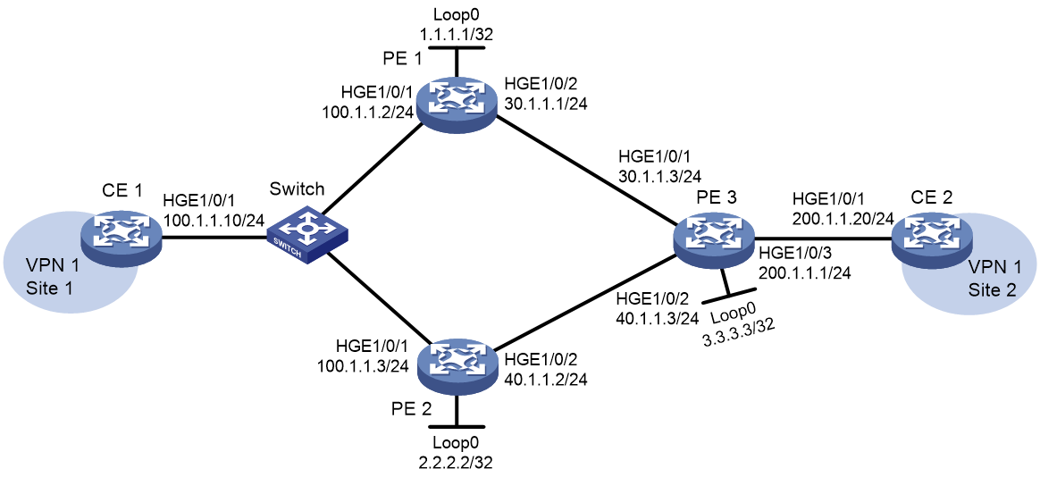
In an MPLS L3VPN, CEs access the backbone network through PEs. When a PE device fails, the sites connected to the CE will be unable to access the backbone network and communicate with other sites. To improve network reliability, a CE is multi-homed to multiple PEs and VRRP is deployed on these PEs for redundant backup.
As shown in Figure 1, the specific networking requirements in this example are as follows:
· CE 1 and CE 2 belong to VPN 1.
· CE 1 is dual-homed to PE 1 and PE 2 through a Layer 2 switch. PE 1 and PE 2 back up each other and provide access services to CE 1.
· When PE 1 is functioning normally, the traffic of CE 1 is forwarded by PE 1. When PE 1 fails, the traffic of CE 1 is forwarded by PE 2.
Analysis
In MPLS L3VPN networking, to achieve redundant backup of PE devices through VRRP, the following configurations need to be performed:
· On PE 1 and PE 2, create a VRRP group on the interface connecting the PE device to CE 1, and configure the same VRRP virtual IP address on the PEs. To ensure priority selection of PE 1 for forwarding traffic, configure a higher priority for PE 1 to be elected as the master. The default priority value is 100, and the greater the value, the higher the priority. Therefore, set the priority value of PE 1 to 120.
· Configure EBGP between PEs and CEs to exchange private network routes. CE 1 establishes EBGP peering with the VRRP virtual IP address of PE 1 and PE 2 to enable traffic switchover between the PEs in case of failure of PE 1 or PE 2.
· Run OSPF on the backbone-side interfaces of the PEs to achieve public network route reachability.
· Establish MP-IBGP peers between the PEs to exchange BGP VPNv4 routes.
· No configuration is required on the switch. Make sure that the three interfaces connecting the switch to CE 1, PE 1, and PE 2 are in the same VLAN.
Data plan
Table 1 Configuration data
|
Configuration Item |
Data |
|
AS number of CE 1 |
65410 |
|
AS number of CE 2 |
65420 |
|
AS number of PE 1, PE 2, and PE 3 |
100 |
|
Virtual IP address of the VRRP group for PE 1 and PE 2 |
100.1.1.1 |
Software versions used
This configuration example was created and verified on Release 5210 or later versions of S12500R.
Procedures
Configuring PE 1
Assigning IP addresses to interfaces
Configuring PE 1
# Assign IP addresses to interfaces Loopback 0 and HundredGigE1/0/2.
<Sysname> system-view
[Sysname] sysname PE1
[PE1] interface loopback 0
[PE1-LoopBack0] ip address 1.1.1.1 255.255.255.255
[PE1-LoopBack0] quit
[PE1] interface hundredgige 1/0/2
[PE1-HundredGigE1/0/2] ip address 30.1.1.1 24
[PE1-HundredGigE1/0/2] quit
Configuring PE 2
# Assign IP addresses to interfaces Loopback 0 and HundredGigE1/0/2.
<Sysname> system-view
[Sysname] sysname PE2
[PE2] interface loopback 0
[PE2-LoopBack0] ip address 2.2.2.2 255.255.255.255
[PE2-LoopBack0] quit
[PE2] interface hundredgige 1/0/2
[PE2-HundredGigE1/0/2] ip address 40.1.1.2 24
[PE2-HundredGigE1/0/2] quit
Configuring PE 3
# Assign IP addresses to interfaces Loopback 0, HundredGigE1/0/1, and HundredGigE1/0/2.
<Sysname> system-view
[Sysname] sysname PE3
[PE3] interface loopback 0
[PE3-LoopBack0] ip address 3.3.3.3 255.255.255.255
[PE3-LoopBack0] quit
[PE3] interface hundredgige 1/0/1
[PE3-HundredGigE1/0/1] ip address 30.1.1.3 24
[PE3-HundredGigE1/0/1] quit
[PE3] interface hundredgige 1/0/2
[PE3-HundredGigE1/0/2] ip address 40.1.1.3 24
[PE3-HundredGigE1/0/2] quit
Configuring CE 1
<Sysname> system-view
[Sysname] sysname CE1
[CE1] interface hundredgige 1/0/1
[CE1-HundredGigE1/0/1] ip address 100.1.1.10 24
[CE1-HundredGigE1/0/1] quit
Configuring CE 2
<Sysname> system-view
[Sysname] sysname CE2
[CE2] interface hundredgige 1/0/1
[CE2-HundredGigE1/0/1] ip address 200.1.1.20 24
[CE2-HundredGigE1/0/1] quit
Configuring OSPF on PEs to achieve route reachability in the public network
Configuring PE 1
[PE1] ospf
[PE1-ospf-1] area 0
[PE1-ospf-1-area-0.0.0.0] network 30.1.1.0 0.0.0.255
[PE1-ospf-1-area-0.0.0.0] network 1.1.1.1 0.0.0.0
[PE1-ospf-1-area-0.0.0.0] quit
[PE1-ospf-1] quit
Configuring PE 2
[PE2] ospf
[PE2-ospf-1] area 0
[PE2-ospf-1-area-0.0.0.0] network 40.1.1.0 0.0.0.255
[PE2-ospf-1-area-0.0.0.0] network 2.2.2.2 0.0.0.0
[PE2-ospf-1-area-0.0.0.0] quit
[PE2-ospf-1] quit
Configuring PE 3
[PE3] ospf
[PE3-ospf-1] area 0
[PE3-ospf-1-area-0.0.0.0] network 30.1.1.0 0.0.0.255
[PE3-ospf-1-area-0.0.0.0] network 40.1.1.0 0.0.0.255
[PE3-ospf-1-area-0.0.0.0] network 3.3.3.3 0.0.0.0
[PE3-ospf-1-area-0.0.0.0] quit
[PE3-ospf-1] quit
After the configuration is completed, PE 1 and PE 2 should have established OSPF neighbors with PE 3. Use the display ospf peer command to verify that the neighbors are in FULL state. Execute the display ip routing-table command to verify that the PEs have learned the routes to the loopback interfaces of each other.
Configuring an MPLS LSR ID and enabling MPLS and MPLS LDP on PEs
Configuring PE 1
[PE1] mpls lsr-id 1.1.1.1
[PE1] mpls ldp
[PE1-ldp] quit
[PE1] interface hundredgige 1/0/2
[PE1-HundredGigE1/0/2] mpls enable
[PE1-HundredGigE1/0/2] mpls ldp enable
[PE1-HundredGigE1/0/2] quit
Configuring PE 2
[PE2] mpls lsr-id 2.2.2.2
[PE2] mpls ldp
[PE2-ldp] quit
[PE2] interface hundredgige 1/0/2
[PE2-HundredGigE1/0/2] mpls enable
[PE2-HundredGigE1/0/2] mpls ldp enable
[PE2-HundredGigE1/0/2] quit
Configuring PE 3
[PE3] mpls lsr-id 3.3.3.3
[PE3] mpls ldp
[PE3-ldp] quit
[PE3] interface hundredgige 1/0/1
[PE3-HundredGigE1/0/1] mpls enable
[PE3-HundredGigE1/0/1] mpls ldp enable
[PE3-HundredGigE1/0/1] quit
[PE3] interface hundredgige 1/0/2
[PE3-HundredGigE1/0/2] mpls enable
[PE3-HundredGigE1/0/2] mpls ldp enable
[PE3-HundredGigE1/0/2] quit
After the configuration is completed, PE 1 and PE 2 should have established LDP sessions with PE 3. Execute the display mpls ldp peer command to verify that the LDP sessions are in Operational state. Execute the display mpls ldp lsp command to verify that the LSPs have been established by LDP.
Configuring MP-IBGP peering between PEs to exchange VPNv4 routes
Configuring PE 1
# Configure MP-IBGP peering between PE 1 and PE 3.
[PE1] bgp 100
[PE1-bgp-default] peer 3.3.3.3 as-number 100
[PE1-bgp-default] peer 3.3.3.3 connect-interface loopback 0
[PE1-bgp-default] address-family vpnv4
[PE1-bgp-default-evpn] peer 3.3.3.3 enable
[PE1-bgp-default-evpn] quit
Configuring PE 2
# Configure PE 2 to establish MP-IBGP peering with PE 3.
[PE2] bgp 100
[PE2-bgp-default] peer 3.3.3.3 as-number 100
[PE2-bgp-default] peer 3.3.3.3 connect-interface loopback 0
[PE2-bgp-default] address-family vpnv4
[PE2-bgp-default-evpn] peer 3.3.3.3 enable
[PE2-bgp-default-evpn] quit
Configuring PE 3
# Configure PE 3 to establish MP-IBGP peering with PE 1 and PE 2.
[PE3] bgp 100
[PE3-bgp-default] peer 1.1.1.1 as-number 100
[PE3-bgp-default] peer 1.1.1.1 connect-interface loopback 0
[PE3-bgp-default] peer 2.2.2.2 as-number 100
[PE3-bgp-default] peer 2.2.2.2 connect-interface loopback 0
[PE3-bgp-default] address-family vpnv4
[PE3-bgp-default-evpn] peer 1.1.1.1 enable
[PE3-bgp-default-evpn] peer 2.2.2.2 enable
[PE3-bgp-default-evpn] quit
After the configuration is completed, execute the display bgp peer vpnv4 command to verify that the BGP peers have been established between PEs and are in Established state.
Configuring VPN instances on PEs
Configuring PE 1
# Create VPN instance vpn1 and configure the RD and RT of the VPN instance.
[PE1] ip vpn-instance vpn1
[PE1-vpn-instance-vpn1] route-distinguisher 1:1
[PE1-vpn-instance-vpn1] vpn-target 1:1 import-extcommunity
[PE1-vpn-instance-vpn1] vpn-target 1:1 export-extcommunity
[PE1-vpn-instance-vpn1] quit
# Bind interface HundredGigE1/0/1 to VPN instance vpn1 and configure an IP address for this interface.
[PE1] interface hundredgige 1/0/1
[PE1-HundredGigE1/0/1] ip binding vpn-instance vpn1
[PE1-HundredGigE1/0/1] ip address 100.1.1.2 24
[PE1-HundredGigE1/0/1] quit
Configuring PE 2
# Create VPN instance vpn1 and configure the RD and RT of the VPN instance.
[PE2] ip vpn-instance vpn1
[PE2-vpn-instance-vpn1] route-distinguisher 1:1
[PE2-vpn-instance-vpn1] vpn-target 1:1 import-extcommunity
[PE2-vpn-instance-vpn1] vpn-target 1:1 export-extcommunity
[PE2-vpn-instance-vpn1] quit
# Bind interface HundredGigE1/0/1 to VPN instance vpn1 and configure an IP address for this interface.
[PE2] interface hundredgige 1/0/1
[PE2-HundredGigE1/0/1] ip binding vpn-instance vpn1
[PE2-HundredGigE1/0/1] ip address 100.1.1.3 24
[PE2-HundredGigE1/0/1] quit
Configuring PE 3
# Create VPN instance vpn1 and configure the RD and RT of the VPN instance.
[PE3] ip vpn-instance vpn1
[PE3-vpn-instance-vpn1] route-distinguisher 1:1
[PE3-vpn-instance-vpn1] vpn-target 1:1 import-extcommunity
[PE3-vpn-instance-vpn1] vpn-target 1:1 export-extcommunity
[PE3-vpn-instance-vpn1] quit
# Bind interface HundredGigE1/0/3 to VPN instance vpn1 and configure an IP address for this interface.
[PE3] interface hundredgige 1/0/3
[PE3-HundredGigE1/0/3] ip binding vpn-instance vpn1
[PE3-HundredGigE1/0/3] ip address 200.1.1.1 24
[PE3-HundredGigE1/0/3] quit
After the configuration is completed, execute the display ip vpn-instance command on the PEs to view the VPN instance configuration. Execute the ping -vpn-instance vpn1 command on the PEs to verify that each PE can ping its own connected CE.
Configuring routing between PEs and CEs
Configuring PE 1
# Configure PE 1 to establish EBGP peering with CE 1, and redistribute VPN routes into BGP.
[PE1] bgp 100
[PE1-bgp-default] ip vpn-instance vpn1
[PE1-bgp-default-vpn1] peer 100.1.1.10 as-number 65410
[PE1-bgp-default-vpn1] address-family ipv4 unicast
[PE1-bgp-default-ipv4-vpn1] peer 100.1.1.10 enable
[PE1-bgp-default-ipv4-vpn1] quit
[PE1-bgp-default-vpn1] quit
Configuring PE 2
# Configure PE 2 to establish EBGP peering with CE 1, and redistribute VPN routes into BGP.
[PE2] bgp 100
[PE2-bgp-default] ip vpn-instance vpn1
[PE2-bgp-default-vpn1] peer 100.1.1.10 as-number 65410
[PE2-bgp-default-vpn1] address-family ipv4 unicast
[PE2-bgp-default-ipv4-vpn1] peer 100.1.1.10 enable
[PE2-bgp-default-ipv4-vpn1] quit
[PE2-bgp-default-vpn1] quit
Configuring PE 3
# Configure PE 3 to establish EBGP peering with CE 2, and redistribute VPN routes into BGP.
[PE3] bgp 100
[PE3-bgp-default] ip vpn-instance vpn1
[PE3-bgp-default-vpn1] peer 200.1.1.20 as-number 65420
[PE3-bgp-default-vpn1] address-family ipv4 unicast
[PE3-bgp-default-ipv4-vpn1] peer 200.1.1.20 enable
[PE3-bgp-default-ipv4-vpn1] quit
[PE3-bgp-default-vpn1] quit
Configuring CE 1
# Establish EBGP peering between the PE and CE, and redistribute direct routes into BGP.
[CE1] bgp 65410
[CE1-bgp-default] peer 100.1.1.1 as-number 100
[CE1-bgp-default] address-family ipv4 unicast
[CE1-bgp-default-ipv4] peer 100.1.1.1 enable
[CE1-bgp-default-ipv4] import-route direct
[CE1-bgp-default-ipv4] quit
[CE1-bgp-default] quit
Configuring CE 2
# Establish EBGP peering between the PE and CE, and redistribute direct routes into BGP.
[CE2] bgp 65420
[CE2-bgp-default] peer 200.1.1.1 as-number 100
[CE2-bgp-default] address-family ipv4 unicast
[CE2-bgp-default-ipv4] peer 200.1.1.1 enable
[CE2-bgp-default-ipv4] import-route direct
[CE2-bgp-default-ipv4] quit
[CE2-bgp-default] quit
After the configuration is completed, execute the display bgp peer ipv4 vpn-instance command on PEs to verify that the BGP peers have been established between the PEs and CEs and have reached Established state.
Configuring VRRP
Configuring PE 1
# On interface HundredGigE 1/0/1, create a VRRP group, set the priority of PE 1 in the VRRP group to 120, and set the preemption delay to 500 centiseconds.
[PE1] interface hundredgige 1/0/1
[PE1-HundredGigE1/0/1] vrrp vrid 1 virtual-ip 100.1.1.1
[PE1-HundredGigE1/0/1] vrrp vrid 1 priority 120
[PE1-HundredGigE1/0/1] vrrp vrid 1 preempt-mode delay 500
[PE1-HundredGigE1/0/1] quit
Configuring PE 2
# On interface HundredGigE 1/0/1, create a VRRP group, and set the preemption delay to 500 centiseconds.
[PE2] interface hundredgige 1/0/1
[PE2-HundredGigE1/0/1] vrrp vrid 1 virtual-ip 100.1.1.1
[PE2-HundredGigE1/0/1] vrrp vrid 1 preempt-mode delay 500
[PE2-HundredGigE1/0/1] quit
Verifying the configuration
Verifying CE 1 and CE 2 intercommunicate through PE 1 when PE 1 operates normally
# On PE 1 and PE 2, view the VRRP group status. The output shows that PE 1 is the master and PE 2 is the backup.
[PE1] display vrrp
IPv4 Virtual Router Information:
Running mode : Standard
Total number of virtual routers : 1
Interface VRID State Running Adver Auth Virtual
Pri Timer Type IP
----------------------------------------------------------------------------
HGE1/0/1 1 Master 120 100 Not supported 100.1.1.1
[PE2] display vrrp
IPv4 Virtual Router Information:
Running mode : Standard
Total number of virtual routers : 1
Interface VRID State Running Adver Auth Virtual
Pri Timer Type IP
----------------------------------------------------------------------------
HGE1/0/1 1 Backup 100 100 Not supported 100.1.1.1
# On PE3, view the routing table information of VPN instance vpn1. The output shows that the next hop for the 100.1.1.0/24 network segment is 1.1.1.1, namely PE 1.
[PE3] display ip routing-table vpn-instance vpn1
Destinations : 6 Routes : 6
Destination/Mask Proto Pre Cost NextHop Interface
100.1.1.0/24 BGP 255 0 1.1.1.1 HGE1/0/1
127.0.0.0/8 Direct 0 0 127.0.0.1 InLoop0
200.1.1.0/24 Direct 0 0 200.1.1.1 HGE1/0/3
200.1.1.1/32 Direct 0 0 127.0.0.1 HGE1/0/3
200.1.1.255/32 Direct 0 0 200.1.1.1 HGE1/0/3
255.255.255.255/32 Direct 0 0 127.0.0.1 InLoop0
# Verify that CE 1 can ping CE 2.
[CE1] ping 200.1.1.20
Ping 200.1.1.20 (200.1.1.20): 56 data bytes, press CTRL+C to break
56 bytes from 200.1.1.20: icmp_seq=0 ttl=253 time=2.000 ms
56 bytes from 200.1.1.20: icmp_seq=1 ttl=253 time=1.000 ms
56 bytes from 200.1.1.20: icmp_seq=2 ttl=253 time=1.000 ms
56 bytes from 200.1.1.20: icmp_seq=3 ttl=253 time=1.000 ms
56 bytes from 200.1.1.20: icmp_seq=4 ttl=253 time=2.000 ms
--- Ping statistics for 200.1.1.20 ---
5 packet(s) transmitted, 5 packet(s) received, 0.0% packet loss
round-trip min/avg/max/std-dev = 1.000/1.400/2.000/0.490 ms
The previous outputs show that when PE 1 is functioning properly, CE 1 and CE 2 can communicate with each other, and the traffic between CE 1 and CE 2 is forwarded through PE1.
Verifying CE 1 and CE 2 intercommunicate through PE 2 when PE fails
# On PE 1 and PE 2, view the VRRP group status. The output shows that PE 2 has become the master.
[PE1] display vrrp
IPv4 Virtual Router Information:
Running mode : Standard
Total number of virtual routers : 1
Interface VRID State Running Adver Auth Virtual
Pri Timer Type IP
----------------------------------------------------------------------------
HGE1/0/1 1 Initialize 120 100 Not supported 100.1.1.1
[PE2] display vrrp
IPv4 Virtual Router Information:
Running mode : Standard
Total number of virtual routers : 1
Interface VRID State Running Adver Auth Virtual
Pri Timer Type IP
----------------------------------------------------------------------------
HGE1/0/1 1 Master 100 100 Not supported 100.1.1.1
# On PE3, view the routing table information of VPN instance vpn1. The output shows that the next hop for the 100.1.1.0/24 network segment is 2.2.2.2, namely PE 2.
[PE3] display ip routing-table vpn-instance vpn1
Destinations : 6 Routes : 6
Destination/Mask Proto Pre Cost NextHop Interface
100.1.1.0/24 BGP 255 0 2.2.2.2 HGE1/0/2
127.0.0.0/8 Direct 0 0 127.0.0.1 InLoop0
200.1.1.0/24 Direct 0 0 200.1.1.1 HGE1/0/3
200.1.1.1/32 Direct 0 0 127.0.0.1 HGE1/0/3
200.1.1.255/32 Direct 0 0 200.1.1.1 HGE1/0/3
255.255.255.255/32 Direct 0 0 127.0.0.1 InLoop0
# Verify that CE 1 can ping CE 2.
[CE1] ping 200.1.1.20
Ping 200.1.1.20 (200.1.1.20): 56 data bytes, press CTRL+C to break
56 bytes from 200.1.1.20: icmp_seq=0 ttl=253 time=2.000 ms
56 bytes from 200.1.1.20: icmp_seq=1 ttl=253 time=2.000 ms
56 bytes from 200.1.1.20: icmp_seq=2 ttl=253 time=2.000 ms
56 bytes from 200.1.1.20: icmp_seq=3 ttl=253 time=2.000 ms
56 bytes from 200.1.1.20: icmp_seq=4 ttl=253 time=1.000 ms
--- Ping statistics for 200.1.1.20 ---
5 packet(s) transmitted, 5 packet(s) received, 0.0% packet loss
round-trip min/avg/max/std-dev = 1.000/1.800/2.000/0.400 ms
The previous outputs show that when PE 1 fails, PE 2 takes over the work of PE 1. CE 1 and CE 2 can communicate with each other, and the traffic between CE 1 and CE 2 is forwarded through PE 2.
Configuration files
· PE 1
#
sysname PE1
#
ip vpn-instance vpn1
route-distinguisher 1:1
vpn-target 1:1 import-extcommunity
vpn-target 1:1 export-extcommunity
#
ospf 1
area 0.0.0.0
network 1.1.1.1 0.0.0.0
network 30.1.1.0 0.0.0.255
#
mpls lsr-id 1.1.1.1
#
mpls ldp
#
interface LoopBack0
ip address 1.1.1.1 255.255.255.255
#
interface HundredGigE1/0/1
port link-mode route
combo enable copper
ip binding vpn-instance vpn1
ip address 100.1.1.2 255.255.255.0
vrrp vrid 1 virtual-ip 100.1.1.1
vrrp vrid 1 priority 120
vrrp vrid 1 preempt-mode delay 500
#
interface HundredGigE1/0/2
port link-mode route
combo enable copper
ip address 30.1.1.1 255.255.255.0
mpls enable
mpls ldp enable
#
bgp 100
peer 3.3.3.3 as-number 100
peer 3.3.3.3 connect-interface LoopBack0
#
address-family vpnv4
peer 3.3.3.3 enable
#
ip vpn-instance vpn1
peer 100.1.1.10 as-number 65410
#
address-family ipv4 unicast
peer 100.1.1.10 enable
#
return
· PE 2
#
sysname PE2
#
ip vpn-instance vpn1
route-distinguisher 1:1
vpn-target 1:1 import-extcommunity
vpn-target 1:1 export-extcommunity
#
ospf 1
area 0.0.0.0
network 2.2.2.2 0.0.0.0
network 40.1.1.0 0.0.0.255
#
mpls lsr-id 2.2.2.2
#
mpls ldp
#
interface LoopBack0
ip address 2.2.2.2 255.255.255.255
#
interface HundredGigE1/0/1
port link-mode route
combo enable copper
ip binding vpn-instance vpn1
ip address 100.1.1.3 255.255.255.0
vrrp vrid 1 virtual-ip 100.1.1.1
vrrp vrid 1 preempt-mode delay 500
#
interface HundredGigE1/0/2
port link-mode route
combo enable copper
ip address 40.1.1.2 255.255.255.0
mpls enable
mpls ldp enable
#
bgp 100
peer 3.3.3.3 as-number 100
peer 3.3.3.3 connect-interface LoopBack0
#
address-family vpnv4
peer 3.3.3.3 enable
#
ip vpn-instance vpn1
peer 100.1.1.10 as-number 65410
#
address-family ipv4 unicast
peer 100.1.1.10 enable
#
return
· PE 3
#
sysname PE3
#
ip vpn-instance vpn1
route-distinguisher 1:1
vpn-target 1:1 import-extcommunity
vpn-target 1:1 export-extcommunity
#
ospf 1
area 0.0.0.0
network 3.3.3.3 0.0.0.0
network 30.1.1.0 0.0.0.255
network 40.1.1.0 0.0.0.255
#
mpls lsr-id 3.3.3.3
#
mpls ldp
#
interface LoopBack0
ip address 3.3.3.3 255.255.255.255
#
interface HundredGigE1/0/1
port link-mode route
combo enable copper
ip address 30.1.1.3 255.255.255.0
mpls enable
mpls ldp enable
#
interface HundredGigE1/0/2
port link-mode route
combo enable copper
ip address 40.1.1.3 255.255.255.0
mpls enable
mpls ldp enable
#
interface HundredGigE1/0/3
port link-mode route
combo enable copper
ip binding vpn-instance vpn1
ip address 200.1.1.1 255.255.255.0
#
bgp 100
peer 1.1.1.1 as-number 100
peer 1.1.1.1 connect-interface LoopBack0
peer 2.2.2.2 as-number 100
peer 2.2.2.2 connect-interface LoopBack0
#
address-family vpnv4
peer 1.1.1.1 enable
peer 2.2.2.2 enable
#
ip vpn-instance vpn1
peer 200.1.1.20 as-number 65420
#
address-family ipv4 unicast
peer 200.1.1.20 enable
#
return
· CE 1
#
sysname CE1
#
interface HundredGigE1/0/1
port link-mode route
combo enable copper
ip address 100.1.1.10 255.255.255.0
#
bgp 65410
peer 100.1.1.1 as-number 100
#
address-family ipv4 unicast
import-route direct
peer 100.1.1.1 enable
#
return
· CE 2
#
sysname CE2
#
interface HundredGigE1/0/1
port link-mode route
combo enable copper
ip address 200.1.1.20 255.255.255.0
#
bgp 65420
peer 200.1.1.1 as-number 100
#
address-family ipv4 unicast
import-route direct
peer 200.1.1.1 enable
#
return
Related documentation
· High Availability Configuration Guide in H3C S12500R Switch Router Series Configuration Guides-R52xx
· High Availability Command Reference in H3C S12500R Switch Router Series Command References-R52xx
· MPLS Configuration Guide in H3C S12500R Switch Router Series Configuration Guides-R52xx
· MPLS Command Reference in H3C S12500R Switch Router Series Command References-R52xx
· High Availability Configuration Guide in H3C S12500R-48Y8C&S12500R-48C6D Switch Router Configuration Guides-R52xx
· High Availability Command Reference in H3C S12500R-48Y8C&S12500R-48C6D Switch Router Command References-R52xx
· MPLS Configuration Guide in H3C S12500R-48Y8C&S12500R-48C6D Switch Router Configuration Guides-R52xx
· MPLS Command Reference in H3C S12500R-48Y8C&S12500R-48C6D Switch Router Command References-R52xx