- Table of Contents
-
- 02-WLAN
- 00-Preface
- 01-AP management configuration
- 02-Radio management configuration
- 03-WLAN access configuration
- 04-WLAN security configuration
- 05-WLAN authentication configuration
- 06-WIPS configuration
- 07-WLAN QoS configuration
- 08-WLAN roaming configuration
- 09-WLAN load balancing configuration
- 10-WLAN radio resource measurement configuration
- 11-Channel scanning configuration
- 12-Band navigation configuration
- 13-WLAN high availability configuration
- 14-802.11r configuration
- 15-Wireless location configuration
- 16-Hotspot 2.0 configuration
- 17-WLAN RRM configuration
- 18-WT configuration
- 19-IoT AP configuration
- 20-CM tunnel configuration
- 21-Cloud connection configuration
- 22-WLAN IP snooping configuration
- 23-WLAN fast forwarding configuration
- Related Documents
-
| Title | Size | Download |
|---|---|---|
| 18-WT configuration | 66.65 KB |
Contents
Configuring PoE for a WTU port
Configuring PoE for a WTU port in AP view
Configuring PoE for a WTU port in AP group's AP model view
Specifying the WT version in AP view
Specifying the WT version in AP group's AP model view
Displaying and maintaining WTs
Configuring WTs
Overview
The wireless terminator solution can be widely applied to multi-room scenarios such as dormitories, apartments, hotels, and small-sized offices. This solution has the following advantages over traditional independent or indoor solutions:
· Cost saving and easy deployment—A wireless terminator (WT) and wireless terminator units (WTUs) are connected through Ethernet cables instead of dedicated lines. The WT directly supplies power to the WTUs through PoE.
· Strong signal strength—Each room has dedicated bandwidth.
· Enhanced network performance and user experience—WTUs can offer high uplink bandwidth.
· Most up-to-date wireless access technology—WTUs support 802.11ac Gigabit and dual-band access.
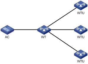
As shown in Figure 1, the wireless terminator solution includes the following entities:
· WT—A WT is an AP that associates with the AC on behalf of WTUs and uses PoE to supply power to the WTUs.
· WTU—A WTU is an indoor AP that only sends and receives wireless packets. A WTU supports 802.11ac Gigabit wireless access, and it can operate simultaneously in 2.4 GHz and 5 GHz bands.
· AC—Manages the WT and the WTUs.
Configuring PoE for a WTU port
A WT uses WTU ports to supply power to its connected WTUs through PoE. For a WTU to operate correctly, make sure PoE is enabled for the WTU port that connects the WT to the WTU.
Configuring PoE for a WTU port in AP view
|
Step |
Command |
Remarks |
|
1. Enter system view. |
system-view |
N/A |
|
2. Enter AP view. |
wlan ap ap-name [ model model-name ] |
The AP must be a WT. |
|
3. Configure PoE for a WTU port. |
poe wtu-port port-number1 [ to port-number2 ] { disable | enable } |
By default, an AP uses the configuration in AP group's AP model view. |
Configuring PoE for a WTU port in AP group's AP model view
|
Step |
Command |
Remarks |
|
1. Enter system view. |
system-view |
N/A |
|
2. Create an AP group and enter its view. |
wlan ap-group group-name |
N/A |
|
3. Enter AP model view. |
ap-model ap-model |
The AP must be a WT. |
|
4. Configure PoE for a WTU port. |
poe wtu-port port-number1 [ to port-number2 ] { disable | enable } |
By default, PoE is enabled for WTU ports. |
Specifying the WT version
If the specified WT version is different from the WT version in use, the WT will restart automatically. Then, it will switch to the specified WT version and restore the factory settings.
Support for WT versions varies by device model.
Specifying the WT version in AP view
|
Step |
Command |
Remarks |
|
1. Enter system view. |
system-view |
N/A |
|
2. Enter AP view. |
wlan ap ap-name [ model model-name ] |
The AP must be a WT. |
|
3. Specify the WT version. |
wt version { 1 | 2 | 3 } |
By default, an AP uses the configuration in AP group's AP model view. |
Specifying the WT version in AP group's AP model view
|
Step |
Command |
Remarks |
|
1. Enter system view. |
system-view |
N/A |
|
2. Create an AP group and enter its view. |
wlan ap-group group-name |
N/A |
|
3. Enter AP model view. |
ap-model ap-model |
The AP must be a WT. |
|
4. Specify the WT version. |
wt version { 1 | 2 | 3 } |
The default setting varies by device model. |
Displaying and maintaining WTs
Execute display commands in any view.
|
Task |
Command |
|
Display WT information and information about the WTUs connected to it. |
display wlan wt { all | name wt-name } |
WT configuration example
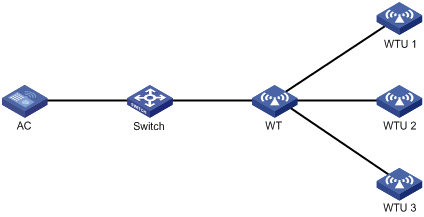
Network requirements
As shown in Figure 2, construct a wireless network by using the wireless terminator solution. WTUs WTU 1, WTU 2, WTU 3 are connected to WTU ports 1, 2, and 3 on the WT, respectively.
Configuration procedure
# Create a WT named wt, and specify its model and serial ID.
<AC> system-view
[AC] wlan ap wt model WT1020
[AC-wlan-ap-wt] serial-id 219801A0SS9156G00072
[AC-wlan-ap-wt] quit
# Create a WTU named wtu1, and specify its model and serial ID.
[AC] wlan ap wtu1 model WTU430
[AC-wlan-ap-wtu1] serial-id 219801A0SS9156G00185
[AC-wlan-ap-wtu1] quit
# Create a WTU named wtu2, and specify its model and serial ID.
[AC] wlan ap wtu2 model WTU430
[AC-wlan-ap-wtu2] serial-id 219801A0SS9156G00133
[AC-wlan-ap-wtu2] quit
# Create a WTU named wtu3, and specify its model and serial ID.
[AC] wlan ap wtu3 model WTU430
[AC-wlan-ap-wtu3] serial-id 219801A0SS9156G00054
[AC-wlan-ap-wtu3] quit
# Configure the WT version as version 1.0.
[AC] wlan ap wt model WT1020
[AC-wlan-ap-wt] wt version 1
[AC-wlan-ap-wt] quit
[AC] quit
Verifying the configuration
# Verify that the WT and WTUs have come online.
<AC> display wlan wt all
WT name : wt
Model : WT1020
Serial ID : 219801A0SS9156G00072
MAC address : 0000-f3ea-0a3e
WTU number : 3
Wireless Terminator Unit:
--------------------------------------------------------
WTU name Port Model Serial ID
---------------------------------------------------------
wtu1 1 WTU430 219801A0SS9156G00185
wtu2 2 WTU430 219801A0SS9156G00133
wtu3 3 WTU430 219801A0SS9156G00054