- Table of Contents
-
- 02-WLAN
- 00-Preface
- 01-AP management configuration
- 02-Radio management configuration
- 03-WLAN access configuration
- 04-WLAN security configuration
- 05-WLAN authentication configuration
- 06-WIPS configuration
- 07-WLAN QoS configuration
- 08-WLAN roaming configuration
- 09-WLAN load balancing configuration
- 10-WLAN radio resource measurement configuration
- 11-Channel scanning configuration
- 12-Band navigation configuration
- 13-WLAN high availability configuration
- 14-802.11r configuration
- 15-Wireless location configuration
- 16-Hotspot 2.0 configuration
- 17-WLAN RRM configuration
- 18-WT configuration
- 19-IoT AP configuration
- 20-CM tunnel configuration
- 21-Cloud connection configuration
- 22-WLAN IP snooping configuration
- 23-WLAN fast forwarding configuration
- Related Documents
-
| Title | Size | Download |
|---|---|---|
| 02-Radio management configuration | 425.56 KB |
Configuration restrictions and guidelines
Enabling or disabling all radios
Enabling or disabling a radio in radio view
Enabling or disabling a radio in AP group radio view
Configuring basic radio functions
Configuring 2.4 GHz radios to use the European channel gap for auto channel selection
Configuring the channel selection blacklist or whitelist
Setting the maximum transmit power
Setting the maximum transmission distance
Setting the maximum number of clients that can associate with an AP
Configuring 802.11b client access
Specifying a collision avoidance mode
Configuring 802.11g protection
Setting the fragmentation threshold
Setting the maximum number of hardware retransmissions
Performing on-demand channel usage measurement
Specifying the A-MPDU aggregation method
Specifying the A-MSDU aggregation method
Configuring access for only 802.11n and 802.11ac clients
Setting the 802.11n bandwidth mode
Configuring 802.11n protection
Configuring 802.11ac functions
Configuring access for only 802.11ac clients
Setting the 802.11ac bandwidth mode
Configuring the smart antenna feature
Displaying and maintaining radio management
Radio management configuration examples
Basic radio function configuration example
Configuring radio management
Overview
Radio frequency (RF) is a rate of electrical oscillation in the range of around 300 KHz to 300 GHz. WLAN uses the 2.4 GHz band (2.4 GHz to 2.4835 GHz) and 5 GHz band (5.150 GHz to 5.350 GHz and 5.725 GHz to 5.850 GHz) radio frequencies as the transmission media.
The term "radio frequency" or its abbreviation "RF" is also used as a synonym for "radio" in wireless communication.
Radio mode
Table 1 provides a comparison of these radio modes.
Table 1 802.11 standards comparison
|
IEEE standard |
Frequency band |
Maximum rate |
Indoor coverage |
Outdoor coverage |
|
||||
|
802.11a |
5 GHz |
54 Mbps |
About 30 meters (98.43 ft) |
About 45 meters (147.64 ft) |
|
||||
|
802.11b |
2.4 GHz |
11 Mbps |
About 30 meters (98.43 ft) |
About 100 meters (328.08 ft) |
|
||||
|
802.11g |
2.4 GHz |
54 Mbps |
About 30 meters (98.43 ft) |
About 100 meters (328.08 ft) |
|
||||
|
802.11n |
2.4 GHz or 5 GHz |
600 Mbps |
About 300 meters (984.3 ft) |
About 600 meters (1968.50 ft) |
|
||||
|
802.11ac |
5 GHz |
6900 Mbps |
About 300 meters (984.3 ft) |
About 600 meters (1968.50 ft) |
|
||||
|
802.11gac |
2.4 GHz |
1600 Mbps |
About 300 meters (984.3 ft) |
About 600 meters (1968.50 ft) |
|||||
|
|
NOTE: · 802.11g, 802.11n, and 802.11ac are backward compatible. · The term "802.11ac" in this document includes 802.11gac unless otherwise specified. |
Channel
A channel is a range of frequencies with a specific bandwidth. There are 14 channels designated in the 2.4 GHz band. The bandwidth for each channel is 20 MHz and each two channels are spaced 5 MHz apart. Among the 14 channels, four groups of non-overlapping channels exist and the most commonly used one contains channels 1, 6, and 11.
The 5 GHz band can provide higher rates and is more immune to interferences. There are 24 non-overlapping channels designated in the 5 GHz band. The channels are spaced 20 MHz apart with a bandwidth of 20 MHz.
Transmit power
Transmit power reflects the signal strength of a wireless device. A higher transmit power enables a radio to cover a larger area but it brings more inferences to adjacent devices. The signal strength decreases as the transmission distance increases.
Transmission rate
Transmission rate refers to the speed at which wireless devices transmit traffic. It varies by radio mode and spreading, coding, and modulation schemes. Rates that are supported by different modes of radios are as follows:
· 802.11a—6 Mbps, 9 Mbps, 12 Mbps, 18 Mbps, 24 Mbps, 36 Mbps, 48 Mbps, and 54 Mbps.
· 802.11b—1 Mbps, 2 Mbps, 5.5 Mbps, and 11 Mbps.
· 802.11g—1 Mbps, 2 Mbps, 5.5 Mbps, 6 Mbps, 9 Mbps, 11 Mbps, 12 Mbps, 18 Mbps, 24 Mbps, 36 Mbps, 48 Mbps, and 54 Mbps.
· 802.11n—Rates for 802.11n radios vary by channel bandwidth. For more information, see "MCS."
· 802.11ac—Rates for 802.11ac radios vary by channel bandwidth and number of spatial streams (NSS). For more information, see "VHT-MCS."
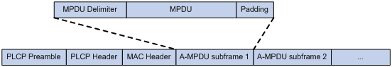
MPDU aggregation
A MAC Protocol Data Unit (MPDU) refers to a data frame in 802.11 format. MPDU aggregation aggregates multiple MPDUs into one aggregate MPDU (A-MPDU) to reduce additional information, ACK frames, and Physical Layer Convergence Procedure (PLCP) header overhead. This improves network throughput and channel efficiency.
All MPDUs in an A-MPDU must have the same QoS priority, source address, and destination address.
Figure 1 A-MPDU format
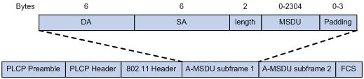
MSDU aggregation
An AP or client encapsulates a MAC Service Data Unit (MSDU) with an Ethernet header and then converts the frame into 802.11 format for forwarding.
MSDU aggregation aggregates multiple MSDUs into one aggregate MSDU (A-MSDU) to reduce PLCP preamble, PLCP header, and MAC header overheads. This improves network throughput and frame forwarding efficiency.
All MSDUs in an A-MSDU must have the same QoS priority, source address, and destination address. When a device receives an A-MSDU, it restores the A-MSDU to multiple MSDUs for processing.
Figure 2 A-MSDU format
MCS
Modulation and Coding Scheme (MCS) defined in IEEE 802.11n-2009 is a value that determines the modulation, coding, and number of spatial streams. An MCS is identified by an MCS index, which is represented by an integer in the range of 0 to 76. An MCS index is the mapping from MCS to a data rate.
Table 2 through Table 9 show sample MCS parameters for both 20 MHz and 40 MHz.
When the bandwidth mode is 20 MHz, MCS indexes 0 through 15 are mandatory for APs, and MCS indexes 0 through 7 are mandatory for clients.
Table 2 MCS parameters (20 MHz, NSS=1)
|
MCS index |
Number of spatial streams |
Modulation |
Data rate (Mbps) |
|
|
800ns GI |
400ns GI |
|||
|
0 |
1 |
BPSK |
6.5 |
7.2 |
|
1 |
1 |
QPSK |
13.0 |
14.4 |
|
2 |
1 |
QPSK |
19.5 |
21.7 |
|
3 |
1 |
16-QAM |
26.0 |
28.9 |
|
4 |
1 |
16-QAM |
39.0 |
43.3 |
|
5 |
1 |
64-QAM |
52.0 |
57.8 |
|
6 |
1 |
64-QAM |
58.5 |
65.0 |
|
7 |
1 |
64-QAM |
65.0 |
72.2 |
Table 3 MCS parameters (20 MHz, NSS=2)
|
MCS index |
Number of spatial streams |
Modulation |
Data rate (Mbps) |
|
|
800ns GI |
400ns GI |
|||
|
8 |
2 |
BPSK |
13.0 |
14.4 |
|
9 |
2 |
QPSK |
26.0 |
28.9 |
|
10 |
2 |
QPSK |
39.0 |
43.3 |
|
11 |
2 |
16-QAM |
52.0 |
57.8 |
|
12 |
2 |
16-QAM |
78.0 |
86.7 |
|
13 |
2 |
64-QAM |
104.0 |
115.6 |
|
14 |
2 |
64-QAM |
117.0 |
130.0 |
|
15 |
2 |
64-QAM |
130.0 |
144.4 |
Table 4 MCS parameters (20 MHz, NSS=3)
|
MCS index |
Number of spatial streams |
Modulation |
Data rate (Mbps) |
|
|
800ns GI |
400ns GI |
|||
|
16 |
3 |
BPSK |
19.5 |
21.7 |
|
17 |
3 |
QPSK |
39.0 |
43.3 |
|
18 |
3 |
QPSK |
58.5 |
65.0 |
|
19 |
3 |
16-QAM |
78.0 |
86.7 |
|
20 |
3 |
16-QAM |
117.0 |
130.0 |
|
21 |
3 |
64-QAM |
156.0 |
173.3 |
|
22 |
3 |
64-QAM |
175.5 |
195.0 |
|
23 |
3 |
64-QAM |
195.0 |
216.7 |
Table 5 MCS parameters (20 MHz, NSS=4)
|
MCS index |
Number of spatial streams |
Modulation |
Data rate (Mbps) |
|
|
800ns GI |
400ns GI |
|||
|
24 |
4 |
BPSK |
26.0 |
28.9 |
|
25 |
4 |
QPSK |
52.0 |
57.8 |
|
26 |
4 |
QPSK |
78.0 |
86.7 |
|
27 |
4 |
16-QAM |
104.0 |
115.6 |
|
28 |
4 |
16-QAM |
156.0 |
173.3 |
|
29 |
4 |
64-QAM |
208.0 |
231.1 |
|
30 |
4 |
64-QAM |
234.0 |
260.0 |
|
31 |
4 |
64-QAM |
260.0 |
288.9 |
Table 6 MCS parameters (40 MHz, NSS=1)
|
MCS index |
Number of spatial streams |
Modulation |
Data rate (Mbps) |
|
|
800ns GI |
400ns GI |
|||
|
0 |
1 |
BPSK |
13.5 |
15.0 |
|
1 |
1 |
QPSK |
27.0 |
30.0 |
|
2 |
1 |
QPSK |
40.5 |
45.0 |
|
3 |
1 |
16-QAM |
54.0 |
60.0 |
|
4 |
1 |
16-QAM |
81.0 |
90.0 |
|
5 |
1 |
64-QAM |
108.0 |
120.0 |
|
6 |
1 |
64-QAM |
121.5 |
135.0 |
|
7 |
1 |
64-QAM |
135.0 |
150.0 |
Table 7 MCS parameters (40 MHz, NSS=2)
|
MCS index |
Number of spatial streams |
Modulation |
Data rate (Mbps) |
|
|
800ns GI |
400ns GI |
|||
|
8 |
2 |
BPSK |
27.0 |
30.0 |
|
9 |
2 |
QPSK |
54.0 |
60.0 |
|
10 |
2 |
QPSK |
81.0 |
90.0 |
|
11 |
2 |
16-QAM |
108.0 |
120.0 |
|
12 |
2 |
16-QAM |
162.0 |
180.0 |
|
13 |
2 |
64-QAM |
216.0 |
240.0 |
|
14 |
2 |
64-QAM |
243.0 |
270.0 |
|
15 |
2 |
64-QAM |
270.0 |
300.0 |
Table 8 MCS parameters (40 MHz, NSS=3)
|
MCS index |
Number of spatial streams |
Modulation |
Data rate (Mbps) |
|
|
800ns GI |
400ns GI |
|||
|
16 |
3 |
BPSK |
40.5 |
45.0 |
|
17 |
3 |
QPSK |
81.0 |
90.0 |
|
18 |
3 |
QPSK |
121.5 |
135.0 |
|
19 |
3 |
16-QAM |
162.0 |
180.0 |
|
20 |
3 |
16-QAM |
243.0 |
270.0 |
|
21 |
3 |
64-QAM |
324.0 |
360.0 |
|
22 |
3 |
64-QAM |
364.5 |
405.0 |
|
23 |
3 |
64-QAM |
405.0 |
450.0 |
Table 9 MCS parameters (40 MHz, NSS=4)
|
MCS index |
Number of spatial streams |
Modulation |
Data rate (Mbps) |
|
|
800ns GI |
400ns GI |
|||
|
24 |
4 |
BPSK |
54.0 |
60.0 |
|
25 |
4 |
QPSK |
108.0 |
120.0 |
|
26 |
4 |
QPSK |
162.0 |
180.0 |
|
27 |
4 |
16-QAM |
216.0 |
240.0 |
|
28 |
4 |
16-QAM |
324.0 |
360.0 |
|
29 |
4 |
64-QAM |
432.0 |
480.0 |
|
30 |
4 |
64-QAM |
486.0 |
540.0 |
|
31 |
4 |
64-QAM |
540.0 |
600.0 |
MCS indexes are classified into the following types:
· Mandatory MCS indexes—Mandatory MCS indexes for an AP. Clients can associate with an 802.11n AP only when they support the mandatory MCS indexes for the AP.
· Supported MCS indexes—MCS indexes supported by an AP except for the mandatory MCS indexes. Supported MCS indexes allow a client that supports both mandatory and supported MCS indexes to use a higher rate to communicate with the AP.
· Multicast MCS index—MCS index corresponding to the rate at which an AP transmits multicast frames.
|
|
NOTE: · For all the MCS data rate tables, see IEEE 802.11n-2009. · Support for MCS indexes depends on the AP model. |
VHT-MCS
802.11 ac uses Very High Throughput Modulation and Coding Scheme (VHT-MCS) indexes to indicate wireless data rates. A VHT-MCS is identified by a VHT-MCS index, which is represented by an integer in the range of 0 to 9. A VHT-MCS index is the mapping from VHT-MCS to a data rate.
802.11ac supports the 20 MHz, 40 MHz, 80 MHz, and 160 MHz bandwidth modes, and supports a maximum of eight spatial streams. 802.11gac supports the 20 MHz and 40 MHz bandwidth modes.
Table 10 through Table 21 show VHT-MCS parameters that are supported by an AP.
Table 10 VHT-MCS parameters (20 MHz, NSS=1)
|
VHT-MCS index |
Modulation |
Data rate (Mbps) |
|
|
800ns GI |
400ns GI |
||
|
0 |
BPSK |
6.5 |
7.2 |
|
1 |
QPSK |
13.0 |
14.4 |
|
2 |
QPSK |
19.5 |
21.7 |
|
3 |
16-QAM |
26.0 |
28.9 |
|
4 |
16-QAM |
39.0 |
43.3 |
|
5 |
64-QAM |
52.0 |
57.8 |
|
6 |
64-QAM |
58.5 |
65.0 |
|
7 |
64-QAM |
65.0 |
72.2 |
|
8 |
256-QAM |
78.0 |
86.7 |
|
9 |
Not valid |
||
Table 11 VHT-MCS parameters (20 MHz, NSS=2)
|
VHT-MCS index |
Modulation |
Data rate (Mbps) |
|
|
800ns GI |
400ns GI |
||
|
0 |
BPSK |
13.0 |
14.4 |
|
1 |
QPSK |
26.0 |
28.9 |
|
2 |
QPSK |
39.0 |
43.3 |
|
3 |
16-QAM |
52.0 |
57.8 |
|
4 |
16-QAM |
78.0 |
86.7 |
|
5 |
64-QAM |
104.0 |
115.6 |
|
6 |
64-QAM |
117.0 |
130.0 |
|
7 |
64-QAM |
130.0 |
144.4 |
|
8 |
256-QAM |
156.0 |
173.3 |
|
9 |
Not valid |
||
Table 12 VHT-MCS parameters (20 MHz, NSS=3)
|
VHT-MCS index |
Modulation |
Data rate (Mbps) |
|
|
800ns GI |
400ns GI |
||
|
0 |
BPSK |
19.5 |
21.7 |
|
1 |
QPSK |
39.0 |
43.3 |
|
2 |
QPSK |
58.5 |
65.0 |
|
3 |
16-QAM |
78.0 |
86.7 |
|
4 |
16-QAM |
117.0 |
130.0 |
|
5 |
64-QAM |
156.0 |
173.3 |
|
6 |
64-QAM |
175.5 |
195.0 |
|
7 |
64-QAM |
195.0 |
216.7 |
|
8 |
256-QAM |
234.0 |
260.0 |
|
9 |
256-QAM |
260.0 |
288.9 |
Table 13 VHT-MCS parameters (20 MHz, NSS=4)
|
VHT-MCS index |
Modulation |
Data rate (Mbps) |
|
|
800ns GI |
400ns GI |
||
|
0 |
BPSK |
26.0 |
28.9 |
|
1 |
QPSK |
52.0 |
57.8 |
|
2 |
QPSK |
78.0 |
86.7 |
|
3 |
16-QAM |
104.0 |
115.6 |
|
4 |
16-QAM |
156.0 |
173.3 |
|
5 |
64-QAM |
208.0 |
231.1 |
|
6 |
64-QAM |
234.0 |
260.0 |
|
7 |
64-QAM |
260.0 |
288.9 |
|
8 |
256-QAM |
312.0 |
346.7 |
|
9 |
Not valid |
||
Table 14 VHT-MCS parameters (40 MHz, NSS=1)
|
VHT-MCS index |
Modulation |
Data rate (Mbps) |
|
|
800ns GI |
400ns GI |
||
|
0 |
BPSK |
13.5 |
15.0 |
|
1 |
QPSK |
27.0 |
30.0 |
|
2 |
QPSK |
40.5 |
45.0 |
|
3 |
16-QAM |
54.0 |
60.0 |
|
4 |
16-QAM |
81.0 |
90.0 |
|
5 |
64-QAM |
108.0 |
120.0 |
|
6 |
64-QAM |
121.5 |
135.0 |
|
7 |
64-QAM |
135.0 |
150.0 |
|
8 |
256-QAM |
162.0 |
180.0 |
|
9 |
256-QAM |
180.0 |
200.0 |
Table 15 VHT-MCS parameters (40 MHz, NSS=2)
|
VHT-MCS index |
Modulation |
Data rate (Mbps) |
|
|
800ns GI |
400ns GI |
||
|
0 |
BPSK |
27.0 |
30.0 |
|
1 |
QPSK |
54.0 |
60.0 |
|
2 |
QPSK |
81.0 |
90.0 |
|
3 |
16-QAM |
108.0 |
120.0 |
|
4 |
16-QAM |
162.0 |
180.0 |
|
5 |
64-QAM |
216.0 |
240.0 |
|
6 |
64-QAM |
243.0 |
270.0 |
|
7 |
64-QAM |
270.0 |
300.0 |
|
8 |
256-QAM |
324.0 |
360.0 |
|
9 |
256-QAM |
360.0 |
400.0 |
Table 16 VHT-MCS parameters (40 MHz, NSS=3)
|
VHT-MCS index |
Modulation |
Data rate (Mbps) |
|
|
800ns GI |
400ns GI |
||
|
0 |
BPSK |
40.5 |
45.0 |
|
1 |
QPSK |
81.0 |
90.0 |
|
2 |
QPSK |
121.5 |
135.0 |
|
3 |
16-QAM |
162.0 |
180.0 |
|
4 |
16-QAM |
243.0 |
270.0 |
|
5 |
64-QAM |
324.0 |
360.0 |
|
6 |
64-QAM |
364.5 |
405.0 |
|
7 |
64-QAM |
405.0 |
450.0 |
|
8 |
256-QAM |
486.0 |
540.0 |
|
9 |
256-QAM |
540.0 |
600.0 |
Table 17 VHT-MCS parameters(40 MHz, NSS=4)
|
VHT-MCS index |
Modulation |
Data rate (Mbps) |
|
|
800ns GI |
400ns GI |
||
|
0 |
BPSK |
54.0 |
60.0 |
|
1 |
QPSK |
108.0 |
120.0 |
|
2 |
QPSK |
162.0 |
180.0 |
|
3 |
16-QAM |
216.0 |
240.0 |
|
4 |
16-QAM |
324.0 |
360.0 |
|
5 |
64-QAM |
432.0 |
480.0 |
|
6 |
64-QAM |
486.0 |
540.0 |
|
7 |
64-QAM |
540.0 |
600.0 |
|
8 |
256-QAM |
648.0 |
720.0 |
|
9 |
256-QAM |
720.0 |
800.0 |
Table 18 VHT-MCS parameters (80 MHz, NSS=1)
|
VHT-MCS index |
Modulation |
Data rate (Mbps) |
|
|
800ns GI |
400ns GI |
||
|
0 |
BPSK |
29.3 |
32.5 |
|
1 |
QPSK |
58.5 |
65.0 |
|
2 |
QPSK |
87.8 |
97.5 |
|
3 |
16-QAM |
117.0 |
130.0 |
|
4 |
16-QAM |
175.5 |
195.0 |
|
5 |
64-QAM |
234.0 |
260.0 |
|
6 |
64-QAM |
263.0 |
292.5 |
|
7 |
64-QAM |
292.5 |
325.0 |
|
8 |
256-QAM |
351.0 |
390.0 |
|
9 |
256-QAM |
390.0 |
433.3 |
Table 19 VHT-MCS parameters (80 MHz, NSS=2)
|
VHT-MCS index |
Modulation |
Data rate (Mbps) |
|
|
800ns GI |
400ns GI |
||
|
0 |
BPSK |
58.5 |
65.0 |
|
1 |
QPSK |
117.0 |
130.0 |
|
2 |
QPSK |
175.5 |
195.0 |
|
3 |
16-QAM |
234.0 |
260.0 |
|
4 |
16-QAM |
351.0 |
390.0 |
|
5 |
64-QAM |
468.0 |
520.0 |
|
6 |
64-QAM |
526.5 |
585.0 |
|
7 |
64-QAM |
585.0 |
650.0 |
|
8 |
256-QAM |
702.0 |
780.0 |
|
9 |
256-QAM |
780.0 |
866.7 |
Table 20 VHT-MCS parameters (80 MHz, NSS=3)
|
VHT-MCS index |
Modulation |
Data rate (Mbps) |
|
|
800ns GI |
400ns GI |
||
|
0 |
BPSK |
87.8 |
97.5 |
|
1 |
QPSK |
175.5 |
195.0 |
|
2 |
QPSK |
263.3 |
292.5 |
|
3 |
16-QAM |
351.0 |
390.0 |
|
4 |
16-QAM |
526.5 |
585.0 |
|
5 |
64-QAM |
702.0 |
780.0 |
|
6 |
Not valid |
||
|
7 |
64-QAM |
877.5 |
975.0 |
|
8 |
256-QAM |
1053.0 |
1170.0 |
|
9 |
256-QAM |
1170.0 |
1300.0 |
Table 21 VHT-MCS parameters (80 MHz, NSS=4)
|
VHT-MCS index |
Modulation |
Data rate (Mbps) |
|
|
800ns GI |
400ns GI |
||
|
0 |
BPSK |
117.0 |
130.0 |
|
1 |
QPSK |
234.0 |
260.0 |
|
2 |
QPSK |
351.0 |
390.0 |
|
3 |
16-QAM |
468.0 |
520.0 |
|
4 |
16-QAM |
702.0 |
780.0 |
|
5 |
64-QAM |
936.0 |
1040.0 |
|
6 |
64-QAM |
1053.0 |
1170.0 |
|
7 |
64-QAM |
1170.0 |
1300.0 |
|
8 |
256-QAM |
1404.0 |
1560.0 |
|
9 |
256-QAM |
1560.0 |
1733.3 |
802.11ac NSSs are classified into the following types:
· Mandatory NSSs—Mandatory NSSs for an AP. Clients can associate with an 802.11ac AP only when they support the mandatory NSSs for the AP.
· Supported NSSs—NSSs supported by an AP except for the mandatory NSSs. Supported NSSs allow a client that supports both mandatory and supported NSSs to use a higher rate to communicate with the AP.
· Multicast NSS—An AP uses a rate in the VHT-MCS data rate table for the NSS to transmit multicast frames.
|
|
NOTE: · For all the VHT-MCS data rate tables, see IEEE 802.11ac-2013. · Support for VHT-MCS indexes depends on the AP model. |
Configuration restrictions and guidelines
The priorities for the configuration in radio view, AP group radio view, and global configuration view are in descending order.
Configuration task list
Enabling or disabling radios
Enabling or disabling all radios
|
|
CAUTION: Disabling all radios terminates wireless services. Use it with caution. |
This feature only takes effect on manual APs and online auto APs.
To enable or disable all radios:
|
Step |
Command |
Remarks |
|
1. Enter system view. |
system-view |
N/A |
|
2. Enable or disable all radios. |
wlan radio { enable | disable } |
By default, radios are disabled unless they are already enabled in radio view or AP group radio view. |
Enabling or disabling a radio in radio view
|
Step |
Command |
Remarks |
|
1. Enter system view. |
system-view |
N/A |
|
2. Create an AP and enter AP view. |
wlan ap ap-name [ model model-name ] |
By default, no AP is created. You must specify the name and model when you create an AP. |
|
3. Enter radio view. |
radio radio-id |
N/A |
|
4. Enable or disable the radio. |
radio { enable | disable } |
By default, a radio is enabled if the wlan radio enable command is executed in system view. If the wlan radio enable command is not executed in system view, a radio uses the configuration in AP group radio view. |
Enabling or disabling a radio in AP group radio view
|
Step |
Command |
Remarks |
|
1. Enter system view. |
system-view |
N/A |
|
2. Create an AP group and enter AP group view. |
wlan ap-group group-name |
By default, the default AP group default-group exists and it cannot be deleted. |
|
3. Enter AP model view. |
ap-model ap-model |
N/A |
|
4. Enter radio view. |
radio radio-id |
N/A |
|
5. Enable or disable the radio. |
radio { enable | disable } |
By default, a radio is disabled unless it is already enabled by using the wlan radio enable command in system view. |
Specifying a radio mode
|
|
CAUTION: Modifying the radio mode logs off all associated clients. |
Support for channels and transmit powers depends on the radio mode. When you change the mode of a radio, the system automatically adjusts the channel and power parameters for the radio.
When you change the radio mode in AP group radio view, the default settings for the commands related to the radio mode are restored.
Specifying a radio mode in radio view
|
Step |
Command |
Remarks |
|
1. Enter system view. |
system-view |
N/A |
|
1. Create an AP and enter AP view. |
wlan ap ap-name [ model model-name ] |
By default, no AP is created. You must specify the name and model when you create an AP. |
|
2. Enter radio view. |
radio radio-id |
N/A |
|
3. Specify a radio mode. |
type { dot11a | dot11ac | dot11an | dot11b | dot11g | dot11gac | dot11gn } |
By default, the radio uses the configuration in AP group view. |
Specifying a radio mode in AP group radio view
|
Step |
Command |
Remarks |
|
1. Enter system view. |
system-view |
N/A |
|
2. Create an AP group and enter AP group view. |
wlan ap-group group-name |
By default, the default AP group default-group exists and it cannot be deleted. |
|
3. Enter AP model view. |
ap-model ap-model |
N/A |
|
4. Enter radio view. |
radio radio-id |
N/A |
|
5. Specify a radio mode. |
type { dot11a | dot11ac | dot11an | dot11b | dot11g | dot11gac | dot11gn } |
The default setting for this command varies by AP model. |
Configuring basic radio functions
Specifying a working channel
Perform this task to reduce interferences from both wireless and non-wireless devices.
You can manually specify a channel or configure the system to automatically select a channel for a radio.
When radar signals are detected on the working channel of a radio, either of the following cases occurs:
· If the channel is a manually specified channel, the radio changes its channel, and switches back to the specified channel after 30 minutes and then starts the quiet timer. If no radar signals are detected within the quiet time, the radio starts to use the channel. If radar signals are detected within the quiet time, the radio changes its channel.
· If the channel is an automatically assigned channel, the radio changes its channel.
Specifying a working channel in radio view
|
Step |
Command |
Remarks |
|
1. Enter system view. |
system-view |
N/A |
|
2. Create an AP and enter AP view. |
wlan ap ap-name [ model model-name ] |
By default, no AP is created. You must specify the name and model when you create an AP. |
|
3. Enter radio view. |
radio radio-id |
N/A |
|
4. Specify a working channel. |
channel { channel-number | auto { lock | unlock } } |
By default, the radio uses the configuration in AP group view. |
Specifying a working channel in AP group radio view
|
Step |
Command |
Remarks |
|
1. Enter system view. |
system-view |
N/A |
|
2. Create an AP group and enter AP group view. |
wlan ap-group group-name |
By default, the default AP group default-group exists and it cannot be deleted. |
|
3. Enter AP model view. |
ap-model ap-model |
N/A |
|
4. Enter radio view. |
radio radio-id |
N/A |
|
5. Specify a working channel. |
channel { channel-number | auto { lock | unlock } } |
By default, the AC automatically selects a channel for the radio and does not lock the channel. |
Configuring 2.4 GHz radios to use the European channel gap for auto channel selection
By default, 2.4 GHz radios use non-European channel gap 5 to automatically select channels 1, 6, and 11. You can use this feature to enable the radios to use European channel gap 6 to automatically select channels 1, 7, and 13.
To configure 2.4 GHz radios to use the European channel gap for auto channel selection:
|
Step |
Command |
Remarks |
|
1. Enter system view. |
system-view |
|
|
2. Enter global configuration view. |
wlan global-configuration |
N/A |
|
3. Configure 2.4 GHz radios to use the European channel gap for auto channel selection. |
auto-channel european-gap enable |
By default, 2.4 GHz radios use the non-European channel gap for auto channel selection. |
Configuring the channel selection blacklist or whitelist
Perform this task for an AP to not select channels in the blacklist or to select only channels in the whitelist in automatic channel selection. You cannot configure both the channel selection blacklist and whitelist for the same AP.
Configuring the channel selection blacklist or whitelist in radio view
|
Step |
Command |
Remarks |
|
1. Enter system view. |
system-view |
N/A |
|
2. Enter AP view. |
wlan ap ap-name [ model model-name ] |
N/A |
|
3. Enter radio view. |
radio radio-id |
N/A |
|
4. Add the specified channels to the channel selection blacklist or whitelist. |
channel auto-select { blacklist | whitelist } channel-number |
By default, a radio uses the configuration in AP group view. |
Configuring the channel selection blacklist or whitelist in AP group radio view
|
Step |
Command |
Remarks |
|
1. Enter system view. |
system-view |
N/A |
|
2. Enter AP group view. |
wlan ap-group group-name |
N/A |
|
3. Enter AP model view. |
ap-model ap-model |
N/A |
|
4. Enter radio view. |
radio radio-id |
N/A |
|
5. Add the specified channels to the channel selection blacklist or whitelist. |
channel auto-select { blacklist | whitelist } channel-number |
By default, no channel selection blacklist or the whitelist exists. |
Setting the antenna type
|
|
NOTE: Antenna types supported by an AP vary by device model. |
If an AP uses a third-party antenna, you must set the antenna type to the type of the antenna that the AP uses.
The antenna gain automatically changes after you set the antenna type to ensure that the transmit power is within the correct range.
Setting the antenna type in radio view
|
Step |
Command |
Remarks |
|
1. Enter system view. |
system-view |
N/A |
|
2. Create an AP and enter AP view. |
wlan ap ap-name [ model model-name ] |
By default, no AP is created. You must specify the name and model when you create an AP. |
|
3. Enter radio view. |
radio radio-id |
N/A |
|
4. Set the antenna type. |
antenna type antenna-type |
By default, the radio uses the configuration in AP group view. |
Setting the antenna type in AP group radio view
|
Step |
Command |
Remarks |
|
1. Enter system view. |
system-view |
N/A |
|
2. Create an AP group and enter AP group view. |
wlan ap-group group-name |
By default, the default AP group default-group exists and it cannot be deleted. |
|
3. Enter AP model view. |
ap-model ap-model |
N/A |
|
4. Enter radio view. |
radio radio-id |
N/A |
|
5. Set the antenna type. |
antenna type antenna-type |
The default antenna type for an AP varies by device model. |
Setting the antenna gain
|
|
IMPORTANT: This feature is available only when an AP uses a third-party antenna. |
Effective Isotropic Radiated Power (EIRP) is the actual transmit power of an antenna, and it is the sum of the antenna gain and the maximum transmit power of the radio.
If an AP uses a third-party antenna, you must set the antenna gain to the gain of the antenna that the AP uses.
Setting the antenna gain in radio view
|
Step |
Command |
Remarks |
|
1. Enter system view. |
system-view |
N/A |
|
2. Create an AP and enter AP view. |
wlan ap ap-name [ model model-name ] |
By default, no AP is created. You must specify the name and model when you create an AP. |
|
3. Enter radio view. |
radio radio-id |
N/A |
|
4. Set the antenna gain. |
custom-antenna gain antenna-gain |
By default, the radio uses the configuration in AP group view. |
Setting the antenna gain in AP group radio view
|
Step |
Command |
Remarks |
|
1. Enter system view. |
system-view |
N/A |
|
2. Create an AP group and enter AP group view. |
wlan ap-group group-name |
By default, the default AP group default-group exists and it cannot be deleted. |
|
3. Enter AP model view. |
ap-model ap-model |
N/A |
|
4. Enter radio view. |
radio radio-id |
N/A |
|
5. Set the antenna gain. |
custom-antenna gain antenna-gain |
By default, the antenna gain is 0 dBi. |
Setting the maximum transmit power
Make sure the maximum transmit power is within the transmit power range supported by a radio. The transmit power range supported by a radio varies by country code, channel, AP model, radio mode, antenna type, and bandwidth mode. If you change these attributes for a radio after you set the maximum transmit power, the configured maximum transmit power might be out of the supported transmit power range. If this happens, the system automatically adjusts the maximum transmit power to a valid value.
If you enable power lock, the locked power becomes the maximum transmit power. For more information about power lock, see "Configuring power lock."
Setting the maximum transmit power in radio view
|
Step |
Command |
Remarks |
|
1. Enter system view. |
system-view |
N/A |
|
2. Create an AP and enter AP view. |
wlan ap ap-name [ model model-name ] |
By default, no AP is created. You must specify the name and model when you create an AP. |
|
3. Enter radio view. |
radio radio-id |
N/A |
|
4. Set the maximum transmit power. |
max-power radio-power |
By default, the radio uses the configuration in AP group view. |
Setting the maximum transmit power in AP group radio view
|
Step |
Command |
Remarks |
|
1. Enter system view. |
system-view |
N/A |
|
2. Create an AP group and enter AP group view. |
wlan ap-group group-name |
By default, the default AP group default-group exists and it cannot be deleted. |
|
3. Enter AP model view. |
ap-model ap-model |
N/A |
|
4. Enter radio view. |
radio radio-id |
N/A |
|
5. Set the maximum transmit power. |
max-power radio-power |
By default, the radio uses the supported maximum transmit power. |
Configuring power lock
If you enable power lock, the current power is locked and becomes the maximum transmit power. The locked power still takes effect after the AC restarts.
If a radio enabled with power lock switches to a new channel that provides lower power than the locked power, the maximum power supported by the new channel takes effect.
Configuring power lock in radio view
|
Step |
Command |
Remarks |
|
1. Enter system view. |
system-view |
N/A |
|
2. Create an AP and enter AP view. |
wlan ap ap-name [ model model-name ] |
By default, no AP is created. You must specify the name and model when you create an AP. |
|
3. Enter radio view. |
radio radio-id |
N/A |
|
4. Configure power lock. |
power-lock { disable | enable } |
By default, the radio uses the configuration in AP group view. |
Configuring power lock in AP group radio view
|
Step |
Command |
Remarks |
|
1. Enter system view. |
system-view |
N/A |
|
2. Create an AP group and enter AP group view. |
wlan ap-group group-name |
By default, the default AP group default-group exists and it cannot be deleted. |
|
3. Enter AP model view. |
ap-model ap-model |
N/A |
|
4. Enter radio view. |
radio radio-id |
N/A |
|
5. Configure power lock. |
power-lock { disable | enable } |
By default, power lock is disabled. |
Setting transmission rates
Transmission rates are classified into the following types:
· Prohibited rates—Rates that cannot be used by an AP.
· Mandatory rates—Rates that the clients must support to associate with an AP.
· Supported rates—Rates that an AP supports. After a client associates with an AP, the client can select a higher rate from the supported rates to communicate with the AP. The AP automatically decreases the transmission rate when great interference, retransmission, or packet dropping is detected and increases the rate when a little interference, retransmission, or packet dropping is detected.
· Multicast rate—Rate at which an AP transmits multicasts and broadcasts. The multicast rate must be selected from the mandatory rates.
Setting the transmission rates in radio view
|
Step |
Command |
Remarks |
|
1. Enter system view. |
system-view |
N/A |
|
2. Create an AP and enter AP view. |
wlan ap ap-name [ model model-name ] |
By default, no AP is created. You must specify the name and model when you create an AP. |
|
3. Enter radio view. |
radio radio-id |
N/A |
|
4. Set the transmission rates for the radio. |
rate { multicast { auto | rate-value } | { disabled | mandatory | supported } rate-value } |
By default, the radio uses the configuration in AP group view. |
Setting the transmission rates in AP group radio view
|
Step |
Command |
Remarks |
|
1. Enter system view. |
system-view |
N/A |
|
2. Create an AP group and enter AP group view. |
wlan ap-group group-name |
By default, the default AP group default-group exists and it cannot be deleted. |
|
3. Enter AP model view. |
ap-model ap-model |
N/A |
|
4. Enter radio view. |
radio radio-id |
N/A |
|
5. Set the transmission rates for the radio. |
rate { multicast { auto | rate-value } | { disabled | mandatory | supported } rate-value } |
The default settings are as follows: · 802.11a/802.11an/802.11ac radios: ¡ Prohibited rates—None. ¡ Mandatory rates—6, 12, and 24. ¡ Multicast rate—Selected from the mandatory rates. ¡ Supported rates—9, 18, 36, 48, and 54. · 802.11b radios: ¡ Prohibited rates—None. ¡ Mandatory rates—1 and 2. ¡ Multicast rate—Selected from the mandatory rates. ¡ Supported rates—5.5, and 11. · 802.11g/802.11gn/802.11gac radios: ¡ Prohibited rates—None. ¡ Mandatory rates—1, 2, 5.5, and 11. ¡ Multicast rate—Selected from the mandatory rates. ¡ Supported rates—6, 9, 12, 18, 24, 36, 48, and 54. |
Setting the preamble type
|
|
IMPORTANT: This feature is applicable only to 802.11b, 802.11g, and 802.11gn radios. |
A preamble is a set of bits in a packet header to synchronize transmission signals between sender and receiver. A short preamble improves network performance and a long preamble ensures compatibility with all wireless devices of early models.
Setting the preamble type in radio view
|
Step |
Command |
Remarks |
|
1. Enter system view. |
system-view |
N/A |
|
2. Create an AP and enter AP view. |
wlan ap ap-name [ model model-name ] |
By default, no AP is created. You must specify the name and model when you create an AP. |
|
3. Enter radio view. |
radio radio-id |
N/A |
|
4. Set the preamble type. |
preamble { long | short } |
By default, the radio uses the configuration in AP group view. |
Setting the preamble type in AP group radio view
|
Step |
Command |
Remarks |
|
1. Enter system view. |
system-view |
N/A |
|
2. Create an AP group and enter AP group view. |
wlan ap-group group-name |
By default, the default AP group default-group exists and it cannot be deleted. |
|
3. Enter AP model view. |
ap-model ap-model |
N/A |
|
4. Enter radio view. |
radio radio-id |
N/A |
|
5. Set the preamble type. |
preamble { long | short } |
By default, a short preamble is used. |
Setting the maximum transmission distance
The strength of wireless signals gradually degrades as the transmission distance increases. The maximum transmission distance of wireless signals depends on the surrounding environment and on whether an external antenna is used.
· Without an external antenna—About 300 meters (984.25 ft).
· With an external antenna—30 km (18.64 miles) to 50 km (31.07 miles).
· In an area with obstacles—35 m (114.83 ft) to 50 m (164.04 ft).
Setting the maximum transmission distance in radio view
|
Step |
Command |
Remarks |
|
1. Enter system view. |
system-view |
N/A |
|
2. Create an AP and enter AP view. |
wlan ap ap-name [ model model-name ] |
By default, no AP is created. You must specify the name and model when you create an AP. |
|
3. Enter radio view. |
radio radio-id |
N/A |
|
4. Set the maximum transmission distance. |
distance distance |
By default, the radio uses the configuration in AP group view. |
Setting the maximum transmission distance in AP group radio view
|
Step |
Command |
Remarks |
|
1. Enter system view. |
system-view |
N/A |
|
2. Create an AP group and enter AP group view. |
wlan ap-group group-name |
By default, the default AP group default-group exists and it cannot be deleted. |
|
3. Enter AP model view. |
ap-model ap-model |
N/A |
|
4. Enter radio view. |
radio radio-id |
N/A |
|
5. Set the maximum transmission distance. |
distance distance |
By default, the maximum transmission distance is 1 km (0.62 miles). |
Setting the beacon interval
Perform this task to enable an AP to broadcast beacon frames at the specified interval. A small beacon interval enables clients to easily detect the AP but consumes more system resources.
Setting the beacon interval in radio view
|
Step |
Command |
Remarks |
|
1. Enter system view. |
system-view |
N/A |
|
2. Create an AP and enter AP view. |
wlan ap ap-name [ model model-name ] |
By default, no AP is created. You must specify the name and model when you create an AP. |
|
3. Enter radio view. |
radio radio-id |
N/A |
|
4. Set the beacon interval. |
beacon-interval interval |
By default, the radio uses the configuration in AP group view. |
Setting the beacon interval in AP group radio view
|
Step |
Command |
Remarks |
|
1. Enter system view. |
system-view |
N/A |
|
2. Create an AP group and enter AP group view. |
wlan ap-group group-name |
By default, the default AP group default-group exists and it cannot be deleted. |
|
3. Enter AP model view. |
ap-model ap-model |
N/A |
|
4. Enter radio view. |
radio radio-id |
N/A |
|
5. Set the beacon interval. |
beacon-interval interval |
By default, the beacon interval is 100 TU. |
Setting the DTIM interval
An AP periodically broadcasts a beacon compliant with the Delivery Traffic Indication Map (DTIM). After the AP broadcasts the beacon, it sends buffered broadcast and multicast frames based on the value of the DTIM interval. For example, if you set the DTIM interval to 5, the AP sends buffered broadcast and multicast frames every five beacon frames.
Setting the DTIM interval in radio view
|
Step |
Command |
Remarks |
|
1. Enter system view. |
system-view |
N/A |
|
2. Create an AP and enter AP view. |
wlan ap ap-name [ model model-name ] |
By default, no AP is created. You must specify the name and model when you create an AP. |
|
3. Enter radio view. |
radio radio-id |
N/A |
|
4. Set the DTIM interval. |
dtim counter |
By default, the radio uses the configuration in AP group view. |
Setting the DTIM interval in AP group radio view
|
Step |
Command |
Remarks |
|
1. Enter system view. |
system-view |
N/A |
|
2. Create an AP group and enter AP group view. |
wlan ap-group group-name |
By default, the default AP group default-group exists and it cannot be deleted. |
|
3. Enter AP model view. |
ap-model ap-model |
N/A |
|
4. Enter radio view. |
radio radio-id |
N/A |
|
5. Set the DTIM interval. |
dtim counter |
By default, the DTIM interval is 1. |
Setting the maximum number of clients that can associate with an AP
When the maximum number of clients is reached on an AP, the AP stops accepting new clients. This prevents the AP from being overloaded.
Setting the maximum number of clients that can associate with an AP in radio view
|
Step |
Command |
Remarks |
|
1. Enter system view. |
system-view |
N/A |
|
2. Create an AP and enter AP view. |
wlan ap ap-name [ model model-name ] |
By default, no AP is created. You must specify the name and model when you create an AP. |
|
3. Enter radio view. |
radio radio-id |
N/A |
|
4. Set the maximum number of clients that can associate with the AP. |
client max-count max-number |
By default, the radio uses the configuration in AP group view. |
Setting the maximum number of clients that can associate with an AP in AP group radio view
|
Step |
Command |
Remarks |
|
1. Enter system view. |
system-view |
N/A |
|
2. Create an AP group and enter AP group view. |
wlan ap-group group-name |
By default, the default AP group default-group exists and it cannot be deleted. |
|
3. Enter AP model view. |
ap-model ap-model |
N/A |
|
4. Enter radio view. |
radio radio-id |
N/A |
|
5. Set the maximum number of clients that can associate with the AP. |
client max-count max-number |
By default, no limit is set for the number of clients that can associate with an AP. |
Configuring 802.11b client access
To reduce the impact of low-speed 802.11b clients and speed up wireless data transmission, you can enable an 802.11g, 802.11gn, or 802.11gac radio to prohibit access for 802.11b clients.
Configuring 802.11b client access in radio view
|
Step |
Command |
Remarks |
|
1. Enter system view. |
system-view |
N/A |
|
2. Create an AP and enter AP view. |
wlan ap ap-name [ model model-name ] |
By default, no AP is created. You must specify the name and model when you create an AP. |
|
3. Enter radio view. |
radio radio-id |
N/A |
|
4. Configure 802.11b client access. |
client dot11b-forbidden { disable | enable } |
By default, the radio uses the configuration in AP group view. |
Configuring 802.11b client access in AP group radio view
|
Step |
Command |
Remarks |
|
1. Enter system view. |
system-view |
N/A |
|
2. Create an AP group and enter AP group view. |
wlan ap-group group-name |
By default, the default AP group default-group exists and it cannot be deleted. |
|
3. Enter AP model view. |
ap-model ap-model |
N/A |
|
4. Enter radio view. |
radio radio-id |
N/A |
|
5. Configure 802.11b client access. |
client dot11b-forbidden { disable | enable } |
By default, the radio accepts 802.11b clients. |
Configuring ANI
Adaptive Noise Immunity (ANI) enables the device to adjust the anti-noise level based on the environment to reduce the interference from the surrounding environment.
Configuring ANI in radio view
|
Step |
Command |
Remarks |
|
1. Enter system view. |
system-view |
N/A |
|
2. Create an AP and enter AP view. |
wlan ap ap-name [ model model-name ] |
By default, no AP is created. You must specify the name and model when you create an AP. |
|
3. Enter radio view. |
radio radio-id |
N/A |
|
4. Configure ANI. |
ani { disable | enable } |
By default, the radio uses the configuration in AP group view. |
Configuring ANI in AP group radio view
|
Step |
Command |
Remarks |
|
1. Enter system view. |
system-view |
N/A |
|
2. Create an AP group and enter AP group view. |
wlan ap-group group-name |
By default, the default AP group default-group exists and it cannot be deleted. |
|
3. Enter AP model view. |
ap-model ap-model |
N/A |
|
4. Enter radio view. |
radio radio-id |
N/A |
|
5. Configure ANI. |
ani { disable | enable } |
By default, ANI is enabled. |
Specifying a collision avoidance mode
Wireless devices operate in half duplex mode and cannot send and receive data simultaneously. 802.11 allows wireless devices to send Request to Send (RTS) or Clear to Send (CTS) packets to avoid collision.
You can specify either of the following collision avoidance modes for an AP:
· RTS/CTS—An AP sends an RTS packet to a client before sending data to the client. After receiving the RTS packet, the client sends a CTS packet to the AP. The AP begins to send data after receiving the CTS packet, and other devices that detect the RTS or CTS packet do not send data within a specific time period.
|
|
NOTE: 802.11b radios support only the RTS/CTS mode. |
· CTS-to-self—An AP sends a CTS packet with its own MAC address as the destination MAC address before sending data to a client. After receiving the CTS-to-self packet, the AP begins to send data, and other devices that detect the CTS-to-self packet do not send data within a specific time period. The CTS-to-self mode reduces the transmission time but might result in hidden node problems.
To ensure wireless resource efficiency, collision avoidance takes effect only when the following conditions are met:
· The packet to be sent is longer than the RTS threshold 2346 bytes.
· 802.11g or 802.11n protection is enabled. For more information about 802.11g or 802.11n protection, see "Configuring 802.11g protection" and "Configuring 802.11n protection."
Specifying a collision avoidance mode in radio view
|
Step |
Command |
Remarks |
|
1. Enter system view. |
system-view |
N/A |
|
2. Enter AP view. |
wlan ap ap-name [ model model-name ] |
N/A |
|
3. Enter radio view. |
radio radio-id |
N/A |
|
4. Specify a collision avoidance mode. |
protection-mode { cts-to-self | rts-cts } |
By default, the radio uses the configuration in AP group view. |
Specifying a collision avoidance mode in AP group radio view
|
Step |
Command |
Remarks |
|
1. Enter system view. |
system-view |
N/A |
|
2. Enter AP group view. |
wlan ap-group group-name |
N/A |
|
3. Enter AP model view. |
ap-model ap-model |
N/A |
|
4. Enter radio view. |
radio radio-id |
N/A |
|
5. Specify a collision avoidance mode. |
protection-mode { cts-to-self | rts-cts } |
By default, the CTS-to-self mode is used. |
Setting the RTS threshold
802.11 allows wireless devices to send Request to Send (RTS) or Clear to Send (CTS) packets to avoid collision. However, excessive RTS and CTS packets consume more system resources and reduce transmission efficiency. You can set an RTS threshold to resolve this problem. The system performs collision avoidance only for packets larger than the RTS threshold.
In a low-density WLAN, increase the RTS threshold to improve the network throughput and efficiency. In a high-density WLAN, decrease the RTS threshold to reduce collisions in the network.
Setting the RTS threshold in radio view
|
Step |
Command |
Remarks |
|
1. Enter system view. |
system-view |
N/A |
|
2. Enter AP view. |
wlan ap ap-name [ model model-name ] |
N/A |
|
3. Enter radio view. |
radio radio-id |
N/A |
|
4. Set the RTS threshold. |
protection-threshold size |
By default, the radio uses the configuration in AP group view. |
Setting the RTS threshold in AP group radio view
|
Step |
Command |
Remarks |
|
1. Enter system view. |
system-view |
N/A |
|
2. Enter AP group view. |
wlan ap-group group-name |
N/A |
|
3. Enter AP model view. |
ap-model ap-model |
N/A |
|
4. Enter radio view. |
radio radio-id |
N/A |
|
5. Set the RTS threshold. |
protection-threshold size |
By default, the RTS threshold is 2346 bytes. |
Configuring 802.11g protection
|
|
IMPORTANT: This feature is applicable only to 802.11g and 802.11n (2.4 GHz) radios. |
When both 802.11b and 802.11g clients exist in a WLAN, transmission collision might occur because they use different modulation modes. 802.11g protection can avoid such avoidance. It enables 802.11g, 802.11n, and 802.11ac devices to send RTS/CTS or CTS-to-self packets to inform 802.11b clients to defer access to the medium. For more information about RTS/CTS or CTS-to-self, see "Specifying a collision avoidance mode."
802.11g, 802.11n, and 802.11ac devices send RTS/CTS or CTS-to-self packets before sending data only when 802.11b signals are detected on the channel.
802.11g protection automatically takes effect when 802.11b clients associate with an 802.11g, 802.11n (2.4 GHz), or 802.11ac AP.
Configuring 802.11g protection in radio view
|
Step |
Command |
Remarks |
|
1. Enter system view. |
system-view |
N/A |
|
2. Enter AP view. |
wlan ap ap-name [ model model-name ] |
N/A |
|
3. Enter radio view. |
radio radio-id |
N/A |
|
4. Configure 802.11g protection. |
dot11g protection { disable | enable } |
By default, the radio uses the configuration in AP group view. |
Configuring 802.11g protection in AP group radio view
|
Step |
Command |
Remarks |
|
1. Enter system view. |
system-view |
N/A |
|
2. Enter AP group view. |
wlan ap-group group-name |
N/A |
|
3. Enter AP model view. |
ap-model ap-model |
N/A |
|
4. Enter radio view. |
radio radio-id |
N/A |
|
5. Configure 802.11g protection. |
dot11g protection { disable | enable } |
By default, 802.11g protection is disabled. |
Setting the fragmentation threshold
Frames larger than the fragmentation threshold are fragmented before transmission. Frames smaller than the fragmentation threshold are transmitted without fragmentation.
In a WLAN with great interference, decrease the fragmentation threshold to improve the network throughput and efficiency.
Setting the fragmentation threshold in radio view
|
Step |
Command |
Remarks |
|
1. Enter system view. |
system-view |
N/A |
|
2. Enter AP view. |
wlan ap ap-name [ model model-name ] |
N/A |
|
3. Enter radio view. |
radio radio-id |
N/A |
|
4. Set the fragmentation threshold. |
fragment-threshold size |
By default, the radio uses the configuration in AP group view. |
Setting the fragmentation threshold in AP group radio view
|
Step |
Command |
Remarks |
|
1. Enter system view. |
system-view |
N/A |
|
2. Enter AP group view. |
wlan ap-group group-name |
N/A |
|
3. Enter AP model view. |
ap-model ap-model |
N/A |
|
4. Enter radio view. |
radio radio-id |
N/A |
|
5. Set the fragmentation threshold. |
fragment-threshold size |
By default, the fragmentation threshold is 2346 bytes. |
Setting the maximum number of hardware retransmissions
In wireless networks, unicast frames require acknowledgements. If a device fails to receive the acknowledgement for a packet, it retransmits the packet.
You can set different values for the maximum number of hardware retransmissions for large frames and small frames. Transmitting large frames requires a large buffer size and a long time because the system performs collision avoidance for large frames before transmission. Therefore, you can reduce the maximum number of hardware retransmissions for large frames to save system buffer and transmission time.
Setting the maximum number of hardware retransmissions in radio view
|
Step |
Command |
Remarks |
|
1. Enter system view. |
system-view |
N/A |
|
2. Enter AP view. |
wlan ap ap-name [ model model-name ] |
N/A |
|
3. Enter radio view. |
radio radio-id |
N/A |
|
4. Set the maximum number of hardware retransmissions for small frames. |
short-retry threshold count |
By default, the radio uses the configuration in AP group view. |
|
5. Set the maximum number of hardware retransmissions for large frames. |
long-retry threshold count |
By default, the radio uses the configuration in AP group view. |
Setting the maximum number of hardware retransmissions in AP group radio view
|
Step |
Command |
Remarks |
|
1. Enter system view. |
system-view |
N/A |
|
2. Enter AP group view. |
wlan ap-group group-name |
N/A |
|
3. Enter AP model view. |
ap-model ap-model |
N/A |
|
4. Enter radio view. |
radio radio-id |
N/A |
|
5. Set the maximum number of hardware retransmissions for small frames. |
short-retry threshold count |
By default, the maximum number of hardware retransmissions is 7 for small frames. |
|
6. Set the maximum number of hardware retransmissions for large frames. |
long-retry threshold count |
By default, the maximum number of hardware retransmissions is 4 for large frames. |
Performing on-demand channel usage measurement
This feature enables an AP to scan supported channels and display the channel usage after scanning. It takes about one second to scan a channel.
To perform on-demand channel usage measurement:
|
Step |
Command |
|
1. Enter system view. |
system-view |
|
2. Create an AP and enter AP view. |
wlan ap ap-name [ model model-name ] |
|
3. Enter radio view. |
radio radio-id |
|
4. Perform on-demand channel usage. |
channel-usage measure |
Configuring 802.11n functions
|
|
NOTE: Support for 802.11n depends on the device model. |
|
|
IMPORTANT: When you configure 802.11n functions for an AP, if another user is configuring 802.11n functions for the same AP, your configuration fails. |
IEEE 802.11n is designated to provide high-quality wireless services and enable WLAN to achieve the same network performance as Ethernet. 802.11n improves the throughput and transmission rate of WLAN by optimizing the physical layer and Media Access Control (MAC) layer.
The physical layer of 802.11n is based on OFDM. 802.11n uses Multiple Input, Multiple Output (MIMO), 40 MHz bandwidth, short Guard Interval (GI), Space-Time Block Coding (STBC), and Low-Density Parity Check (LDPC) to achieve high throughput at the physical layer. It uses A-MPDU, A-MSDU, and Block Acknowledgment (BA) to improve transmission efficiency at the MAC layer.
Specifying the A-MPDU aggregation method
Specifying the A-MPDU aggregation method in radio view
|
Step |
Command |
Remarks |
|
1. Enter system view. |
system-view |
N/A |
|
2. Create an AP and enter AP view. |
wlan ap ap-name [ model model-name ] |
By default, no AP is created. You must specify the name and model when you create an AP. |
|
3. Enter radio view. |
radio radio-id |
N/A |
|
4. Specify the A-MPDU aggregation method. |
a-mpdu { disable | enable } |
By default, the radio uses the configuration in AP group view. |
Specifying the A-MPDU aggregation method in AP group radio view
|
Step |
Command |
Remarks |
|
1. Enter system view. |
system-view |
N/A |
|
2. Create an AP group and enter AP group view. |
wlan ap-group group-name |
By default, the default AP group default-group exists and it cannot be deleted. |
|
3. Enter AP model view. |
ap-model ap-model |
N/A |
|
4. Enter radio view. |
radio radio-id |
N/A |
|
5. Specify the A-MPDU aggregation method. |
a-mpdu { disable | enable } |
By default, the A-MPDU aggregation method is disabled. |
Specifying the A-MSDU aggregation method
Specifying the A-MSDU aggregation method in radio view
|
Step |
Command |
Remarks |
|
1. Enter system view. |
system-view |
N/A |
|
1. Create an AP and enter AP view. |
wlan ap ap-name [ model model-name ] |
By default, no AP is created. You must specify the name and model when you create an AP. |
|
2. Enter radio view. |
radio radio-id |
N/A |
|
3. Specify the A-MSDU aggregation method. |
By default, the radio uses the configuration in AP group view. |
Specifying the A-MSDU aggregation method in AP group radio view
|
Step |
Command |
Remarks |
|
1. Enter system view. |
system-view |
N/A |
|
2. Create an AP group and enter AP group view. |
wlan ap-group group-name |
By default, the default AP group default-group exists and cannot be deleted. |
|
3. Enter AP model view. |
ap-model ap-model |
N/A |
|
4. Enter radio view. |
radio radio-id |
N/A |
|
5. Specify the A-MSDU aggregation method. |
a-msdu { disable | enable } |
By default, the A-MSDU aggregation method is enabled. |
Configuring short GI
802.11 OFDM fragments frames to data blocks for transmission. It uses GI to ensure that the data block transmissions do not interfere with each other and are immune to transmission delays.
The GI used by 802.11a/g is 800 ns. 802.11n supports a short GI of 400 ns, which provides a 10% increase in data rate.
Both the 20 MHz and 40 MHz bandwidth modes support short GI.
Configuring short GI in radio view
|
Step |
Command |
Remarks |
|
1. Enter system view. |
system-view |
N/A |
|
2. Create an AP and enter AP view. |
wlan ap ap-name [ model model-name ] |
By default, no AP is created. You must specify the name and model when you create an AP. |
|
3. Enter radio view. |
radio radio-id |
N/A |
|
4. Configure short GI. |
By default, the radio uses the configuration in AP group view. |
Configuring short GI in AP group radio view
|
Step |
Command |
Remarks |
|
1. Enter system view. |
system-view |
N/A |
|
2. Create an AP group and enter AP group view. |
wlan ap-group group-name |
By default, the default AP group default-group exists and cannot be deleted. |
|
3. Enter AP model view. |
ap-model ap-model |
N/A |
|
4. Enter radio view. |
radio radio-id |
N/A |
|
5. Configure short GI. |
short-gi { disable | enable } |
By default, short GI is enabled. |
Configuring LDPC
802.11n introduces the Low-Density Parity Check (LDPC) mechanism to increase the signal-to-noise ratio and enhance the transmission quality. LDPC takes effect only when both ends support LDPC.
Configuring LDPC in radio view
|
Step |
Command |
Remarks |
|
1. Enter system view. |
system-view |
N/A |
|
2. Create an AP and enter AP view. |
wlan ap ap-name [ model model-name ] |
By default, no AP is created. You must specify the name and model when you create an AP. |
|
3. Enter radio view. |
radio radio-number |
N/A |
|
4. Configure LDPC. |
ldpc { disable | enable } |
By default, the radio uses the configuration in AP group view. |
Configuring LDPC in AP group radio view
|
Step |
Command |
Remarks |
|
1. Enter system view. |
system-view |
N/A |
|
2. Create an AP group and enter AP group view. |
wlan ap-group group-name |
By default, the default AP group default-group exists and cannot be deleted. |
|
3. Enter AP model view. |
ap-model ap-model |
N/A |
|
4. Enter radio view. |
radio radio-id |
N/A |
|
5. Configure LDPC. |
ldpc { disable | enable } |
By default, LDPC is disabled. |
Configuring STBC
The Space-Time Block Coding (STBC) mechanism can enhance the reliability of data transmission and does not require high transmission rates for clients.
Configuring STBC in radio view
|
Step |
Command |
Remarks |
|
1. Enter system view. |
system-view |
N/A |
|
2. Create an AP and enter AP view. |
wlan ap ap-name [ model model-name ] |
By default, no AP is created. You must specify the name and model when you create an AP. |
|
3. Enter radio view. |
radio radio-number |
N/A |
|
4. Configure STBC. |
stbc { disable | enable } |
By default, the radio uses the configuration in AP group view. |
Configuring STBC in AP group radio view
|
Step |
Command |
Remarks |
|
1. Enter system view. |
system-view |
N/A |
|
2. Create an AP group and enter AP group view. |
wlan ap-group group-name |
By default, the default AP group default-group exists and cannot be deleted. |
|
3. Enter AP model view. |
ap-model ap-model |
N/A |
|
4. Enter radio view. |
radio radio-id |
N/A |
|
5. Configure STBC. |
stbc { disable | enable } |
By default, STBC is enabled. |
Setting MCS indexes
Follow these restrictions and guidelines when you set MCS indexes for an 802.11n AP:
· 802.11n clients use the rate corresponding to the MCS index to send unicast frames, and 802.11a/b/g clients use the 802.11a/b/g rate to send unicast frames.
· If you do not set a multicast MCS index, 802.11n clients and the AP use the 802.11a/b/g multicast rate to send multicast frames. If you set a multicast MCS index, either of following cases occurs:
¡ The AP and clients use the rate corresponding to the multicast MCS index to send multicast frames if only 802.11n clients exist.
¡ The AP and clients use the 802.11a/b/g multicast rate to send multicast frames if any 802.11a/b/g clients exist.
· When you set the maximum mandatory or supported MCS index, you actually specify a range. For example, if you set the maximum mandatory MCS index to 5, rates corresponding to MCS indexes 0 through 5 are configured as 802.11n mandatory rates.
Setting MCS indexes in radio view
|
Step |
Command |
Remarks |
|
1. Enter system view. |
system-view |
N/A |
|
1. Create an AP and enter AP view. |
wlan ap ap-name [ model model-name ] |
By default, no AP is created. You must specify the name and model when you create an AP. |
|
2. Enter radio view. |
radio radio-id |
N/A |
|
dot11n mandatory maximum-mcs index |
The default settings are as follows: · If the maximum supported MCS index is set, no maximum mandatory MCS index is set. · If the maximum supported MCS index is not set, the radio uses the configuration in AP group view. |
|
|
4. Set the maximum supported MCS index. |
dot11n support maximum-mcs index |
The default settings are as follows: · If the maximum mandatory MCS index is set, the maximum supported MCS index is 76. · If the maximum mandatory MCS index is not set, the radio uses the configuration in AP group view. The maximum supported MCS index cannot be smaller than the maximum mandatory MCS index. |
|
5. Set the multicast MCS index. |
The default settings are as follows: · If the maximum supported MCS index or the maximum mandatory MCS index is set, no multicast MCS index is set. · If neither the maximum supported MCS index nor the maximum mandatory MCS index is set, the radio uses the configuration in AP group view. The multicast MCS index cannot be greater than the maximum mandatory MCS index. |
Setting MCS indexes in AP group radio view
|
Step |
Command |
Remarks |
|
1. Enter system view. |
system-view |
N/A |
|
2. Create an AP group and enter AP group view. |
wlan ap-group group-name |
By default, the default AP group default-group exists and it cannot be deleted. |
|
3. Enter AP model view. |
ap-model ap-model |
N/A |
|
4. Enter radio view. |
radio radio-id |
N/A |
|
5. Set the maximum mandatory MCS index. |
dot11n mandatory maximum-mcs index |
By default, no maximum mandatory MCS index is set. |
|
6. Set the maximum supported MCS index. |
dot11n support maximum-mcs index |
By default, the maximum supported MCS index is 76. The maximum supported MCS index cannot be smaller than the maximum mandatory MCS index. |
|
7. Set the multicast MCS index. |
dot11n multicast-mcs index |
By default, no multicast MCS index is set. The multicast MCS index cannot be greater than the maximum mandatory MCS index. |
Configuring access for only 802.11n and 802.11ac clients
To reduce the impact of low-speed 802.11a/b/g clients and speed up wireless data transmission, you can enable an AP to accept only 802.11n and 802.11ac clients.
Configuring access for only 802.11n and 802.11ac clients in radio view
|
Step |
Command |
Remarks |
|
1. Enter system view. |
system-view |
N/A |
|
2. Create an AP and enter AP view. |
wlan ap ap-name [ model model-name ] |
By default, no AP is created. You must specify the name and model when you create an AP. |
|
3. Enter radio view. |
radio radio-id |
N/A |
|
4. Configure access for only 802.11n and 802.11ac clients. |
By default, the radio uses the configuration in AP group view. |
Configuring access for only 802.11n and 802.11ac clients in AP group radio view
|
Step |
Command |
Remarks |
|
1. Enter system view. |
system-view |
N/A |
|
2. Create an AP group and enter AP group view. |
wlan ap-group group-name |
By default, the default AP group default-group exists and it cannot be deleted. |
|
3. Enter AP model view. |
ap-model ap-model |
N/A |
|
4. Enter radio view. |
radio radio-id |
N/A |
|
5. Configure access for only 802.11n and 802.11ac clients. |
client dot11n-only { disable | enable } |
By default, this feature is disabled. |
Setting the 802.11n bandwidth mode
802.11n uses the channel structure of 802.11a/b/g, but the number of subchannels in a 20 MHz channel for transmitting data is increased to 52. This improves data transmission rate.
802.11n binds two adjacent 20 MHz channels to form a 40 MHz channel (one primary channel and one secondary channel). This provides a simple way to double the data rate.
The bandwidth for a radio varies by the bandwidth mode and chip capability.
Setting the 802.11n bandwidth mode in radio view
|
Step |
Command |
Remarks |
|
1. Enter system view. |
system-view |
N/A |
|
1. Create an AP and enter AP view. |
wlan ap ap-name [ model model-name ] |
By default, no AP is created. You must specify the name and model when you create an AP. |
|
2. Enter radio view. |
radio radio-id |
N/A |
|
channel band-width { 20 | 40 [ auto-switch ] } |
By default, the radio uses the configuration in AP group view. Only 802.11gn radios support the auto-switch keyword. |
Setting the 802.11n bandwidth mode in AP group radio view
|
Step |
Command |
Remarks |
|
1. Enter system view. |
system-view |
N/A |
|
2. Create an AP group and enter AP group view. |
wlan ap-group group-name |
By default, the default AP group default-group exists and it cannot be deleted. |
|
3. Enter AP model view. |
ap-model ap-model |
N/A |
|
4. Enter radio view. |
radio radio-id |
N/A |
|
5. Set the 802.11n bandwidth mode. |
channel band-width { 20 | 40 [ auto-switch ] } |
By default, the bandwidth mode is 40 MHz for 802.11an radios and 20 MHz for 802.11gn radios. Only 802.11gn radios support the auto-switch keyword. |
Specifying a MIMO mode
|
|
NOTE: Number of spatial streams supported by a radio varies by AP model. |
Multiple-input and multiple-output (MIMO) enables a radio to send and receive wireless signals through multiple spatial streams to improve system capacity and spectrum usage without requiring higher bandwidth.
A radio can operate in one of the following MIMO modes:
· 1x1—Sends and receives wireless signals through one spatial stream.
· 2x2—Sends and receives wireless signals through two spatial streams.
· 3x3—Sends and receives wireless signals through three spatial streams.
· 4x4—Sends and receives wireless signals through four spatial streams.
Specifying a MIMO mode in radio view
|
Step |
Command |
Remarks |
|
1. Enter system view. |
system-view |
N/A |
|
2. Create an AP and enter AP view. |
wlan ap ap-name [ model model-name ] |
By default, no AP is created. You must specify the name and model when you create an AP. |
|
3. Enter radio view. |
radio radio-id |
N/A |
|
4. Specify a MIMO mode. |
mimo { 1x1 | 2x2 | 3x3 | 4x4 } |
By default, the radio uses the configuration in AP group view. |
Specifying a MIMO mode in AP group radio view
|
Step |
Command |
Remarks |
|
1. Enter system view. |
system-view |
N/A |
|
2. Create an AP group and enter AP group view. |
wlan ap-group group-name |
By default, the default AP group default-group exists and it cannot be deleted. |
|
3. Enter AP model view. |
ap-model ap-model |
N/A |
|
4. Enter radio view. |
radio radio-id |
N/A |
|
5. Specify a MIMO mode. |
mimo { 1x1 | 2x2 | 3x3 | 4x4 } |
The default MIMO mode for a radio varies by AP model. |
Configuring energy saving
After you enable the energy saving feature, the MIMO mode of a radio automatically changes to 1x1 if no clients associate with the radio. This reduces power consumption.
Configuring energy saving in radio view
|
Step |
Command |
Remarks |
|
1. Enter system view. |
system-view |
N/A |
|
1. Create an AP and enter AP view. |
wlan ap ap-name [ model model-name ] |
By default, no AP is created. You must specify the name and model when you create an AP. |
|
2. Enter radio view. |
radio radio-id |
N/A |
|
3. Configure energy saving. |
green-energy-management { disable | enable } |
By default, the radio uses the configuration in AP group view. |
Configuring energy saving in AP group radio view
|
Step |
Command |
Remarks |
|
1. Enter system view. |
system-view |
N/A |
|
2. Create an AP group and enter AP group view. |
wlan ap-group group-name |
By default, the default AP group default-group exists and it cannot be deleted. |
|
3. Enter AP model view. |
ap-model ap-model |
N/A |
|
4. Enter radio view. |
radio radio-id |
N/A |
|
5. Configure energy saving. |
green-energy-management { disable | enable } |
By default, energy saving is disabled. |
Configuring 802.11n protection
When both 802.11n and non-802.11n clients exist in a WLAN, transmission collision might occur because they use different modulation modes. 802.11n protection can avoid such avoidance. It enables 802.11n devices to send RTS/CTS or CTS-to-self packets to inform non-802.11n clients to defer access to the medium. For more information about RTS/CTS or CTS-to-self, see "Specifying a collision avoidance mode."
802.11n devices send RTS/CTS or CTS-to-self packets before sending data only when non-802.11n signals are detected on the channel.
802.11n protection automatically takes effect when non-802.11n clients associate with an 802.11n AP.
|
|
NOTE: 802.11n devices refer to 802.11n and 802.11ac devices. |
Configuring 802.11n protection in radio view
|
Step |
Command |
Remarks |
|
1. Enter system view. |
system-view |
N/A |
|
2. Enter AP view. |
wlan ap ap-name [ model model-name ] |
N/A |
|
3. Enter radio view. |
radio radio-id |
N/A |
|
4. Configure 802.11n protection. |
dot11n protection { disable | enable } |
By default, the radio uses the configuration in AP group view. |
Configuring 802.11n protection in AP group radio view
|
Step |
Command |
Remarks |
|
1. Enter system view. |
system-view |
N/A |
|
2. Enter AP group view. |
wlan ap-group group-name |
N/A |
|
3. Enter AP model view. |
ap-model ap-model |
N/A |
|
4. Enter radio view. |
radio radio-id |
N/A |
|
5. Configure 802.11n protection. |
dot11n protection { disable | enable } |
By default, 802.11n protection is disabled. |
Configuring 802.11ac functions
|
|
NOTE: Support for 802.11ac depends on the device model. |
|
|
IMPORTANT: When you configure 802.11ac functions for an AP, if another user is configuring 802.11ac functions for the same AP, your configuration fails. |
Based on 802.11n, 802.11ac further increases the data transmission rate and improves the network performance by providing higher bandwidth, more spatial streams, and more advanced modulation schemes.
Setting NSSs
Follow these restrictions and guidelines when you set NSSs for an 802.11ac AP:
· If the AP supports an NSS, it supports all VHT-MCS indexes for the NSS.
· 802.11ac clients use the rate corresponding to the VHT-MCS index for the NSS to send unicast frames, and non-802.11ac clients use the 802.11a/b/g/n rate to send unicast frames.
· If you do not set a multicast NSS, 802.11ac clients and the AP use the 802.11a/b/g/n multicast rate to send multicast frames. If you set a multicast NSS and specify a VHT-MCS index, either of following cases occurs:
¡ The AP and clients use the rate corresponding to the VHT-MCS index for the NSS to send multicast frames if all clients are 802.11ac clients.
¡ The AP and clients use the 802.11a/b/g/n multicast rate to send multicast frames if any non-802.11ac clients exist.
· When you set the maximum mandatory or supported NSS, you actually specify a range. For example, if you set the maximum mandatory NSS to 5, rates corresponding to VHT-MCS indexes for NSSs 1 through 5 are configured as 802.11ac mandatory rates.
Setting NSSs in radio view
|
Step |
Command |
Remarks |
|
1. Enter system view. |
system-view |
N/A |
|
2. Create an AP and enter AP view. |
wlan ap ap-name [ model model-name ] |
By default, no AP is created. You must specify the name and model when you create an AP. |
|
3. Enter radio view. |
radio radio-id |
N/A |
|
4. Set the maximum mandatory NSS. |
dot11ac mandatory maximum-nss nss-number |
The default settings are as follows: · If the maximum supported NSS is set, no maximum mandatory NSS is set. · If the maximum supported NSS is not set, the radio uses the configuration in AP group view. |
|
5. Set the maximum supported NSS. |
dot11ac support maximum-nss nss-number |
The default settings are as follows: · If the maximum mandatory NSS is set, the maximum supported NSS is 8. · If the maximum mandatory NSS is not set, the radio uses the configuration in AP group view. The maximum supported NSS cannot be smaller than the maximum mandatory NSS. |
|
6. Set the multicast NSS and specify a VHT-MCS index. |
dot11ac multicast-nss nss-number vht-mcs index |
The default settings are as follows: · If the maximum supported NSS or the maximum mandatory NSS is set, no multicast NSS is set. · If neither the maximum supported NSS nor the maximum mandatory NSS is set, the radio uses the configuration in AP group view. The multicast NSS cannot be greater than the maximum mandatory NSS. |
Setting NSSs in AP group radio view
|
Step |
Command |
Remarks |
|
1. Enter system view. |
system-view |
N/A |
|
2. Create an AP group and enter AP group view. |
wlan ap-group group-name |
By default, the default AP group default-group exists and it cannot be deleted. |
|
3. Enter AP model view. |
ap-model ap-model |
N/A |
|
4. Enter radio view. |
radio radio-id |
N/A |
|
5. Set the maximum mandatory NSS. |
dot11ac mandatory maximum-nss nss-number |
By default, no maximum mandatory NSS is set. |
|
6. Set the maximum supported NSS. |
dot11ac support maximum-nss nss-number |
By default, the maximum supported NSS is 8. |
|
7. Set the multicast NSS and specify a VHT-MCS index. |
dot11ac multicast-nss nss-number vht-mcs index |
By default, no multicast NSS is set. |
Configuring access for only 802.11ac clients
To reduce the impact of low-speed 802.11a/b/g/n clients and speed up wireless data transmission, you can enable an AP to accept only 802.11ac clients.
Configuring access for only 802.11ac clients in radio view
|
Step |
Command |
Remarks |
|
1. Enter system view. |
system-view |
N/A |
|
2. Create an AP and enter AP view. |
wlan ap ap-name [ model model-name ] |
By default, no AP is created. You must specify the name and model when you create an AP. |
|
3. Enter radio view. |
radio radio-id |
N/A |
|
4. Configure access for only 802.11ac clients. |
client dot11ac-only { disable | enable } |
By default, the radio uses the configuration in AP group view. |
Configuring access for only 802.11ac clients in AP group radio view
|
Step |
Command |
Remarks |
|
1. Enter system view. |
system-view |
N/A |
|
2. Create an AP group and enter AP group view. |
wlan ap-group group-name |
By default, the default AP group default-group exists and it cannot be deleted. |
|
3. Enter AP model view. |
ap-model ap-model |
N/A |
|
4. Enter radio view. |
radio radio-id |
N/A |
|
5. Configure access for only 802.11ac clients. |
client dot11ac-only { disable | enable } |
By default, 802.11ac radios accept 802.11a, 802.11an, and 802.11ac clients, and 802.11gac radios accept 802.11b, 802.11gn, and 802.11gac clients. |
Setting the 802.11ac bandwidth mode
802.11ac uses the channel structure of 802.11n and increases the maximum bandwidth from 40 MHz to 80 MHz. 802.11ac can bind two adjacent 20 MHz channels to form a 40 MHz channel and bind two adjacent 40 MHz channels to form an 80 MHz channel.
If the current channel of a radio does not support the specified bandwidth mode, the radio clears the channel configuration and selects another channel.
|
|
NOTE: 802.11gac supports the 20 MHz and 40 MHz bandwidth modes. |
Figure 3 802.11ac bandwidth modes
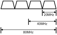
Setting the 802.11ac bandwidth mode in radio view
|
Step |
Command |
Remarks |
|
1. Enter system view. |
system-view |
N/A |
|
2. Create an AP and enter AP view. |
wlan ap ap-name [ model model-name ] |
By default, no AP is created. You must specify the name and model when you create an AP. |
|
3. Enter radio view. |
radio radio-id |
N/A |
|
4. Set the 802.11ac bandwidth mode. |
· Set the 802.11ac bandwidth mode: · Set the 802.11gac bandwidth mode: |
By default, the radio uses the configuration in AP group view. |
Setting the 802.11ac bandwidth mode in AP group radio view
|
Step |
Command |
Remarks |
|
1. Enter system view. |
system-view |
N/A |
|
2. Create an AP group and enter AP group view. |
wlan ap-group group-name |
By default, the default AP group default-group exists and it cannot be deleted. |
|
3. Enter AP model view. |
ap-model ap-model |
N/A |
|
4. Enter radio view. |
radio radio-id |
N/A |
|
5. Set the 802.11ac bandwidth mode. |
· Set
the 802.11ac bandwidth mode: · Set
the 802.11gac bandwidth mode: |
By default, the bandwidth mode is 80 MHz and 20 MHz for 802.11ac and 802.11gac radios, respectively. |
Configuring TxBF
|
|
NOTE: Support for this feature depends on the AP model. |
Transmit beamforming (TxBF) enables an AP to adjust transmitting parameters based on the channel information to focus RF signals on intended clients. This feature improves the RF signal quality. TxBF includes single-user TxBF and multi-user TxBF.
· Single-user TxBF—Single-user TxBF enables an AP to improve the signal to one intended client. Single-user TxBF is applicable to WLANs that have widely spread clients, poor network quality, and serious signal attenuation.
· Multi-user TxBF—Multi-user TxBF is part of 802.11ac Wave2. Multi-user TxBF enables an AP to focus different RF signals on their intended clients to reduce interference and transmission delay. This improves traffic throughput and bandwidth usage. Multi-user TxBF is applicable to WLANs that have a large number of clients and require high bandwidth usage and low transmission delay.
Configuring TxBF in radio view
|
Step |
Command |
Remarks |
|
1. Enter system view. |
system-view |
N/A |
|
2. Create an AP and enter AP view. |
wlan ap ap-name [ model model-name ] |
By default, no APs exist. You must specify the name and model when you create an AP. |
|
3. Enter radio view. |
radio radio-id |
N/A |
|
4. Configure single-user TxBF. |
su-txbf { disable | enable } |
By default, a radio uses the configuration in AP group radio view. |
|
5. Configure multi-user TxBF. |
mu-txbf { disable | enable } |
By default, a radio uses the configuration in AP group radio view. Multi-user TxBF takes effect only when single-user TxBF is enabled. |
Configuring TxBF in AP group radio view
|
Step |
Command |
Remarks |
|
1. Enter system view. |
system-view |
N/A |
|
2. Create an AP group and enter AP group view. |
wlan ap-group group-name |
By default, a system-defined AP group exists. This AP group is named default-group and cannot be deleted. |
|
3. Enter AP model view. |
ap-model ap-model |
N/A |
|
4. Enter radio view. |
radio radio-id |
N/A |
|
5. Configure single-user TxBF. |
su-txbf { disable | enable } |
By default, single-user TxBF is enabled. |
|
6. Configure multi-user TxBF. |
mu-txbf { disable | enable } |
By default, multi-user TxBF is enabled. Multi-user TxBF takes effect only when single-user TxBF is enabled. |
Configuring the smart antenna feature
|
|
NOTE: Support for this feature depends on the device model. |
|
|
IMPORTANT: This feature is applicable to only 802.11n and 802.11ac radios. |
The smart antenna feature enables an AP to automatically adjust the antenna parameters based on the client location and channel information to improve signal quality and stability.
You can configure a radio to operate in one of the following smart antenna modes:
· Auto—Uses the high availability mode for audio and video packets, and uses the high throughput mode for other packets.
· High-availability—Applicable to WLANs that require stable bandwidth, this mode reduces noise and interference impacts and ensures the bandwidth for clients.
· High-throughput—Applicable to WLANs that require high performance, this mode enhances signal strength and association capability.
Configuring the smart antenna feature in radio view
|
Step |
Command |
Remarks |
|
1. Enter system view. |
system-view |
N/A |
|
2. Create an AP and enter AP view. |
wlan ap ap-name [ model model-name ] |
By default, no AP is created. You must specify the name and model when you create an AP. |
|
3. Enter radio view. |
radio radio-id |
N/A |
|
4. Enable the smart antenna feature. |
smart antenna enable |
By default, the radio uses the configuration in AP group view. |
|
5. Specify a smart antenna mode. |
smart-antenna policy { auto | high-availability | high-throughput } |
By default, the radio uses the configuration in AP group view. |
Configuring the smart antenna feature in AP group radio view
|
Step |
Command |
Remarks |
|
1. Enter system view. |
system-view |
N/A |
|
2. Create an AP group and enter AP group view. |
wlan ap-group group-name |
By default, the default AP group default-group exists and cannot be deleted. |
|
3. Enter AP model view. |
ap-model ap-model |
N/A |
|
4. Enter radio view. |
radio radio-id |
N/A |
|
5. Enable the smart antenna feature. |
smart antenna enable |
By default, the smart antenna feature is enabled. |
|
6. Specify a smart antenna mode. |
smart-antenna policy { auto | high-availability | high-throughput } |
By default, the auto mode is used. |
Displaying and maintaining radio management
Execute display commands in any view and reset commands in user view.
|
Task |
Command |
|
Display AP radio information. |
display wlan ap { all | name ap-name } radio [ frequency-band { 5 | 2.4 } ] |
|
Display radio channel information. |
display wlan ap { all | name ap-name } radio channel |
|
Display radio type information. |
display wlan ap { all | name ap-name } radio type |
|
Display radio statistics. |
display wlan ap { all | name ap-name } radio-statistics |
|
Clear radio statistics. |
reset wlan ap { all | name ap-name } radio-statistics |
Radio management configuration examples
Basic radio function configuration example
Network requirements
As shown in Figure 4, create a manual AP and set the radio mode, working channel, and maximum transmit power to 802.11gn, channel 11, and 19 dBm, respectively.

Configuration procedure
# Create the manual AP ap1, and specify its model and serial ID.
<AC> system-view
[AC] wlan ap ap1 model WA4320i-ACN
[AC-wlan-ap-ap1] serial-id 219801A0CNC138011454
# Enter radio view of radio 2.
[AC-wlan-ap-ap1] radio 2
# Set the radio mode to dot11gn.
[AC-wlan-ap-ap1-radio-2] type dot11gn
# Configure radio 2 to work on channel 11.
[AC-wlan-ap-ap1-radio-2] channel 11
# Set the maximum transmit power to 19 dBm.
[AC-wlan-ap-ap1-radio-2] max-power 19
# Enable radio 2.
[AC-wlan-ap-ap1-radio-2] radio enable
[AC-wlan-ap-ap1-radio-2] return
Verifying the configuration
# View information about all radios.
<AC> display wlan ap all verbose
Total number of APs: 1
Total number of connected APs: 1
Total number of connected manual APs: 1
Total number of connected auto APs: 0
Total number of connected common APs: 1
Total number of connected WTUs: 0
Total number of inside APs: 0
Maximum supported APs: 3072
Remaining APs: 3071
AP name : ap1
AP ID : 1
AP group name : default-group
State : Run
Backup type : Master
Online time : 0 days 1 hours 25 minutes 12 seconds
System up time : 0 days 2 hours 22 minutes 12 seconds
Model : WA4320i-ACN
Region code : CN
Region code lock : Disable
Serial ID : 219801A0CNC138011454
MAC address : 0AFB-423B-893C
IP address : 192.168.1.50
UDP port number : 65488
H/W version : Ver.C
S/W version : R2206P02
Boot version : 1.01
Description : wtp1
Priority : 4
Echo interval : 10 seconds
Statistics report interval : 50 seconds
Fragment size (data) : 1500
Fragment size (control) : 1450
MAC type : Local MAC & Split MAC
Tunnel mode : Local Bridging & 802.3 Frame & Native Frame
Discovery type : Static Configuration
Retransmission count : 3
Retransmission interval : 5 seconds
Firmware upgrade : Enabled
Sent control packets : 1
Received control packets : 1
Echo requests : 147
Lost echo responses : 0
Average echo delay : 3
Last reboot reason : User soft reboot
Latest IP address : 10.1.0.2
Tunnel down reason : Request wait timer expired
Connection count : 1
Backup Ipv4 : Not configured
Backup Ipv6 : Not configured
Tunnel encryption : Disabled
LED mode : Normal
Remote configuration : Enabled
Radio 1:
Basic BSSID : 7848-59f6-3940
Admin state : Up
Radio mode : 802.11ac
Antenna type : internal
Client dot11ac-only : Disabled
Client dot11n-only : Disabled
Channel band-width : 20/40/80MHz
Secondary channel offset : SCB
Short GI for 20MHz : Supported
Short GI for 40MHz : Supported
Short GI for 80MHz : Supported
Short GI for 160MHz : Not supported
A-MSDU : Enabled
A-MPDU : Enabled
LDPC : Not Supported
STBC : Supported
Operational VHT-MCS Set:
Mandatory : Not configured
Supported : NSS1 0,1,2,3,4,5,6,7,8,9
NSS2 0,1,2,3,4,5,6,7,8,9
Multicast : Not configured
Operational HT MCS Set:
Mandatory : Not configured
Supported : 0, 1, 2, 3, 4, 5, 6, 7, 8, 9,
10, 11, 12, 13, 14, 15
Multicast : Not configured
Channel : 44(auto)
Max power : 20 dBm
Operational rate:
Mandatory : 6, 12, 24 Mbps
Multicast : Auto
Supported : 9, 18, 36, 48, 54 Mbps
Disabled : Not configured
Distance : 1 km
ANI : Enabled
Fragmentation threshold : 2346 bytes
Beacon interval : 100 TU
Protection threshold : 2346 bytes
Long retry threshold : 4
Short retry threshold : 7
Maximum rx duration : 2000 ms
Noise Floor : –102 dBm
Smart antenna : Enabled
Smart antenna policy : Auto
Protection mode : rts-cts
Continuous mode : N/A
HT protection mode : No protection
Radio 2:
Basic BSSID : 7848-59f6-3950
Admin state : Up
Radio mode : 802.11n(2.4GHz)
Antenna type : internal
Client dot11n-only : Disabled
Channel band-width : 20MHz
Secondary channel offset : SCN
Short GI for 20MHz : Supported
Short GI for 40MHz : Supported
A-MSDU : Enabled
A-MPDU : Enabled
LDPC : Not Supported
STBC : Supported
Operational HT MCS Set:
Mandatory : Not configured
Supported : 0, 1, 2, 3, 4, 5, 6, 7, 8, 9,
10, 11, 12, 13, 14, 15
Multicast : Not configured
Channel : 11
Max power : 19 dBm
Preamble type : Short
Operational rate:
Mandatory : 1, 2, 5.5, 11 Mbps
Multicast : Auto
Supported : 6, 9, 12, 18, 24, 36, 48, 54 Mbps
Disabled : Not configured
Distance : 1 km
ANI : Enabled
Fragmentation threshold : 2346 bytes
Beacon interval : 100 TU
Protection threshold : 2346 bytes
Long retry threshold : 4
Short retry threshold : 7
Maximum rx duration : 2000 ms
Noise Floor : –105 dBm
Smart antenna : Enabled
Smart antenna policy : Auto
Protection mode : rts-cts
Continuous mode : N/A
HT protection mode : No protection
802.11n configuration example
Network requirements
As shown in Figure 5, specify radio 1 on the AP as an 802.11an radio, and enable the A-MSDU and A-MPDU aggregation methods on the radio.
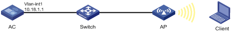
Configuration procedure
# Create the manual AP ap1, and specify its model and serial ID.
<AC> system-view
[AC] wlan ap ap1 model WA4320i-ACN
[AC-wlan-ap-ap1] serial-id 210235A1BSC123000050
# Enter radio view of radio 1 on AP 1, and specify the radio as an 802.11an radio.
[AC-wlan-ap-ap1] radio 1
[AC-wlan-ap-ap1-radio-1] type dot11an
# Enable the A-MPDU and A-MSDU aggregation methods.
[AC-wlan-ap-ap1-radio-1] a-mpdu enable
[AC-wlan-ap-ap1-radio-1] a-msdu enable
# Enable radio 1.
[AC-wlan-ap-ap1-radio-1] radio enable
[AC-wlan-ap-ap1-radio-1] return
Verifying the configuration
# View information about radios on AP 1.
<AC> display wlan ap name ap1 verbose
AP name : ap1
AP ID : 1
AP group name : default-group
State : Run
Backup type : Master
Online time : 0 days 1 hours 25 minutes 12 seconds
System up time : 0 days 2 hours 22 minutes 12 seconds
Model : WA4320i-ACN
Region code : CN
Region code lock : Disable
Serial ID : 219801A0CNC138011454
MAC address : 0AFB-423B-893C
IP address : 192.168.1.50
UDP port number : 65488
H/W version : Ver.C
S/W version : R2206P02
Boot version : 1.01
Description : wtp1
Priority : 4
Echo interval : 10 seconds
Statistics report interval : 50 seconds
Fragment size (data) : 1500
Fragment size (control) : 1450
MAC type : Local MAC & Split MAC
Tunnel mode : Local Bridging & 802.3 Frame & Native Frame
Discovery type : Static Configuration
Retransmission count : 3
Retransmission interval : 5 seconds
Firmware upgrade : Enabled
Sent control packets : 1
Received control packets : 1
Echo requests : 147
Lost echo responses : 0
Average echo delay : 3
Last reboot reason : User soft reboot
Latest IP address : 10.1.0.2
Tunnel down reason : Request wait timer expired
Connection count : 1
Backup Ipv4 : Not configured
Backup Ipv6 : Not configured
Tunnel encryption : Disabled
LED mode : Normal
Remote configuration : Enabled
Radio 1:
Basic BSSID : 7848-59f6-3940
Admin state : Up
Radio mode : 802.11n(5GHz)
Antenna type : internal
Client dot11ac-only : Disabled
Client dot11n-only : Disabled
Channel band-width : 20/40/80MHz
Secondary channel offset : SCB
Short GI for 20MHz : Supported
Short GI for 40MHz : Supported
Short GI for 80MHz : Supported
Short GI for 160MHz : Not supported
A-MSDU : Enabled
A-MPDU : Enabled
LDPC : Not Supported
STBC : Supported
Operational VHT-MCS Set:
Mandatory : Not configured
Supported : NSS1 0,1,2,3,4,5,6,7,8,9
NSS2 0,1,2,3,4,5,6,7,8,9
Multicast : Not configured
Operational HT MCS Set:
Mandatory : Not configured
Supported : 0, 1, 2, 3, 4, 5, 6, 7, 8, 9,
10, 11, 12, 13, 14, 15
Multicast : Not configured
Channel : 44(auto)
Max power : 20 dBm
Operational rate:
Mandatory : 6, 12, 24 Mbps
Multicast : Auto
Supported : 9, 18, 36, 48, 54 Mbps
Disabled : Not configured
Distance : 1 km
ANI : Enabled
Fragmentation threshold : 2346 bytes
Beacon interval : 100 TU
Protection threshold : 2346 bytes
Long retry threshold : 4
Short retry threshold : 7
Maximum rx duration : 2000 ms
Noise Floor : –102 dBm
Smart antenna : Enabled
Smart antenna policy : Auto
Protection mode : rts-cts
Continuous mode : N/A
HT protection mode : No protection
Radio 2:
Basic BSSID : 7848-59f6-3950
Admin state : Up
Radio mode : 802.11n(2.4GHz)
Antenna type : internal
Client dot11n-only : Disabled
Channel band-width : 20MHz
Secondary channel offset : SCN
Short GI for 20MHz : Supported
Short GI for 40MHz : Supported
A-MSDU : Enabled
A-MPDU : Enabled
LDPC : Not Supported
STBC : Supported
Operational HT MCS Set:
Mandatory : Not configured
Supported : 0, 1, 2, 3, 4, 5, 6, 7, 8, 9,
10, 11, 12, 13, 14, 15
Multicast : Not configured
Channel : 11
Max power : 19 dBm
Preamble type : Short
Operational rate:
Mandatory : 1, 2, 5.5, 11 Mbps
Multicast : Auto
Supported : 6, 9, 12, 18, 24, 36, 48, 54 Mbps
Disabled : Not configured
Distance : 1 km
ANI : Enabled
Fragmentation threshold : 2346 bytes
Beacon interval : 100 TU
Protection threshold : 2346 bytes
Long retry threshold : 4
Short retry threshold : 7
Maximum rx duration : 2000 ms
Noise Floor : -105 dBm
Smart antenna : Enabled
Smart antenna policy : Auto
Protection mode : rts-cts
Continuous mode : N/A
HT protection mode : No protection