- Table of Contents
-
- 02-WLAN
- 00-Preface
- 01-AP management configuration
- 02-Radio management configuration
- 03-WLAN access configuration
- 04-WLAN security configuration
- 05-WLAN authentication configuration
- 06-WIPS configuration
- 07-WLAN QoS configuration
- 08-WLAN roaming configuration
- 09-WLAN load balancing configuration
- 10-WLAN radio resource measurement configuration
- 11-Channel scanning configuration
- 12-Band navigation configuration
- 13-WLAN high availability configuration
- 14-802.11r configuration
- 15-Wireless location configuration
- 16-Hotspot 2.0 configuration
- 17-WLAN RRM configuration
- 18-WT configuration
- 19-IoT AP configuration
- 20-CM tunnel configuration
- 21-Cloud connection configuration
- 22-WLAN IP snooping configuration
- 23-WLAN fast forwarding configuration
- Related Documents
-
| Title | Size | Download |
|---|---|---|
| 17-WLAN RRM configuration | 332.22 KB |
Configuration restrictions and guidelines
WLAN RRM configuration task list
Configuration restrictions and guidelines
Configuring DFS trigger parameters
Configuring scheduled auto-DFS
Configuring an RRM holddown group
Configuration restrictions and guidelines
Configuring TPC trigger parameters
Setting the minimum transmit power
Configuring an RRM holddown group
Configuring spectrum management
Setting the power constraint mode
Setting the channel switch mode
Setting the transmit power capability match mode
Setting the channel capability match mode
Enabling SNMP notifications for WLAN RRM
Displaying and maintaining WLAN RRM
WLAN RRM configuration examples
Periodic auto-DFS configuration example
Scheduled auto-DFS configuration example
Periodic auto-TPC configuration example
Spectrum management configuration example
Configuring WLAN RRM
Overview
WLAN Radio Resource Management (RRM) provides an intelligent and scalable radio management solution. RRM enables the AC to monitor its associated radios and perform radio resource monitoring, dynamic frequency selection (DFS), and transmit power control (TPC). This allows a WLAN to adapt to environment changes and maintain the optimal radio resource condition.
Dynamic frequency selection
Two adjacent radios on the same channel might cause signal collision, and other radio sources such as radar signals and microwave ovens might interfere with the operation of radios. DFS can solve these problems.
With DFS, the AC selects an optimal channel for each radio in real time to avoid co-channel interference and interference from other radio sources.
The following factors will trigger DFS:
· Error code rate—Physical layer error code rate and CRC error rate. CRC error rate shows the proportion of packets with CRC errors among all 802.11 packets.
· Interference rate—Proportion of interference packets among all data packets. Interference packets are packets destined for other radios.
· Retransmission count—Data retransmissions caused by failure to receive ACK messages.
· Radar signal—Radar signals detected on the current channel. In this case, the AC selects a new channel and immediately notifies the radio to change its working channel.
The AC uses the following procedure to perform DFS for a radio:
1. Detects the current channel and selects an optimal channel when the CRC error threshold, the interference threshold, or the system-defined retransmission threshold is reached on the current channel.
2. Compares the quality between the current channel and the optimal channel. The radio does not use the optimal channel until the quality gap between the two channels exceeds the tolerance level.
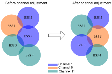
Figure 1 shows a DFS example. When the quality of the channels for BSS 1, BSS 3, and BSS 5 reaches a DFS threshold, the AC selects an optimal channel for each of them. This ensures wireless service quality.
Figure 1 Dynamic frequency selection
Transmit power control
TPC enables the AC to dynamically control access point transmit power based on real-time WLAN conditions. It can achieve desired RF coverage while avoiding channel interference between radios.
The AC maintains a neighbor report for each radio on its associated APs to record information about other radios detected by this radio. The AC can manage only radios associated with the AC.
The AC uses the following procedure to perform TPC for a radio:
1. Determines whether the number of manageable radios detected by this radio reaches the adjacency factor.
If the number does not reach the adjacency factor, the radio uses the maximum transmit power.
If the number reaches the adjacency factor, the AC goes to step 2.
2. Ranks the radio's RSSIs stored in neighbor reports of other radios in descending order.
3. Compares the RSSI specified by the adjacency factor with the power adjustment threshold and takes one of the following actions:
¡ Decreases the radio's transmit power when the RSSI rises above the threshold.
¡ Increases the radio's transmit power when the RSSI drops below the threshold.
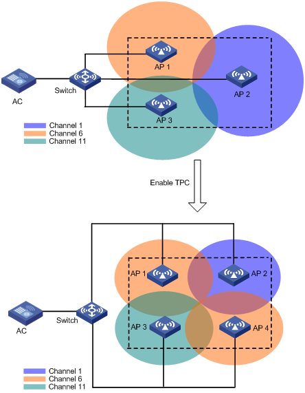
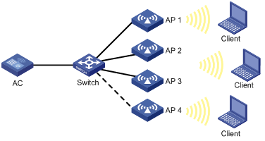
As shown in Figure 2, each AP has only one radio enabled. Before AP 4 joins, the radios use the maximum transmit power because the number of manageable radios detected by each radio has not reached adjacency factor 3. After AP 4 joins, the AC uses TPC to adjust the transmit powers for all radios because the number of manageable radios detected by each radio has reached adjacency factor 3.
Figure 2 Transmit power control
Spectrum management
Spectrum management is 802.11h compliant. It is used on 5 GHz WLANs to ensure that clients meet the regulatory requirements for operation in the 5 GHz band. It enables an AP to notify its associated clients of the allowed maximum transmit power. The AP can deny the association request from a client if the power and channel of the client do not meet the regulatory requirements.
Configuration restrictions and guidelines
The priorities for the configuration in AP view, AP group view, and global configuration view are in descending order.
WLAN RRM configuration task list
|
Tasks at a glance |
|
· (Optional.) Configuring DFS trigger parameters · (Required.) Choose one of the following tasks: ¡ Configuring periodic auto-DFS ¡ Configuring scheduled auto-DFS · (Optional.) Configuring an RRM holddown group |
|
· (Optional.) Setting the TPC mode · (Optional.) Configuring TPC trigger parameters · (Optional.) Setting the minimum transmit power · (Required.) Choose either of the following tasks: ¡ Configuring periodic auto-TPC · (Optional.) Configuring an RRM holddown group |
|
Configuring spectrum management: · (Required.) Enabling spectrum management · (Optional.) Setting the power constraint mode · (Optional.) Setting the channel switch mode · (Optional.) Setting the transmit power capability match mode · (Optional.) Setting the channel capability match mode |
|
(Optional.) Configuring a radio baseline |
|
(Optional.) Enabling radio scanning |
|
(Optional.) Enabling SNMP notifications for WLAN RRM |
Configuring DFS
The AC supports the following DFS methods:
· Periodic auto-DFS—The AC automatically performs DFS for a radio at the channel calibration interval.
· Scheduled auto-DFS—The AC performs DFS at the specified time in a time range. Use this method when interference is severe to avoid affecting ongoing wireless services.
· On-demand DFS—The AC waits for a channel calibration interval and then performs DFS for all radios. You must perform this task every time you want the AC to perform DFS for radios.
Configuration restrictions and guidelines
For DFS to work, configure the AC to automatically select a channel for a radio and not lock the channel by using the channel auto unlock command. For more information about the channel { channel-number | auto { lock | unlock } } command, see WLAN Command Reference.
Configuring DFS trigger parameters
|
|
IMPORTANT: As a best practice for accurate channel adjustment, configure the same DFS trigger parameters for all radios enabled with DFS. |
Configuring DFS trigger parameters in RRM view
|
Step |
Command |
Remarks |
|
1. Enter system view. |
system-view |
N/A |
|
2. Create an AP and enter AP view. |
wlan ap ap-name [ model model-name ] |
Specify the AP model when you create an AP. |
|
3. Enter radio view. |
radio radio-id |
N/A |
|
4. Enter RRM view. |
rrm |
N/A |
|
5. Set the CRC error threshold. |
crc-error-threshold percent |
By default, the configuration in AP group RRM view is used. |
|
6. Set the interference threshold. |
interference-threshold percent |
By default, the configuration in AP group RRM view is used. |
|
7. Set the tolerance level. |
tolerance-level percent |
By default, the configuration in AP group RRM view is used. |
Configuring DFS trigger parameters in AP group RRM view
|
Step |
Command |
Remarks |
|
1. Enter system view. |
system-view |
N/A |
|
2. Enter AP group view. |
wlan ap-group group-name |
N/A |
|
3. Enter AP model view. |
ap-model ap-model |
N/A |
|
4. Enter radio view. |
radio radio-id |
N/A |
|
5. Enter RRM view. |
rrm |
N/A |
|
6. Set the CRC error threshold. |
crc-error-threshold percent |
By default, the CRC error threshold is 20. |
|
7. Set the interference threshold. |
interference-threshold percent |
By default, the interference threshold is 50. |
|
8. Set the tolerance level. |
tolerance-level percent |
By default, the tolerance level is 20. |
Configuring periodic auto-DFS
Configuring periodic auto-DFS in RRM view
|
Step |
Command |
Remarks |
|
1. Enter system view. |
system-view |
N/A |
|
2. (Optional.) Set the channel calibration interval. |
wlan rrm calibration-channel interval minutes |
By default, the channel calibration interval is 8 minutes. |
|
3. Create an AP and enter AP view. |
wlan ap ap-name [ model model-name ] |
N/A |
|
4. Enter radio view. |
radio radio-id |
N/A |
|
5. Enter RRM view. |
rrm |
N/A |
|
6. Enable auto-DFS. |
calibrate-channel self-decisive enable |
By default, the configuration in AP group view RRM is used. |
|
7. Set the auto-DFS mode to periodic. |
calibrate-channel mode periodic |
By default, the configuration in AP group RRM view is used. |
Configuring periodic auto-DFS in AP group RRM view
|
Step |
Command |
Remarks |
|
1. Enter system view. |
system-view |
N/A |
|
2. (Optional.) Set the channel calibration interval. |
wlan rrm calibration-channel interval minutes |
By default, the channel calibration interval is 8 minutes. |
|
3. Enter AP group view. |
wlan ap-group group-name |
N/A |
|
4. Enter AP model view. |
ap-model ap-model |
N/A |
|
5. Enter radio view. |
radio radio-id |
N/A |
|
6. Enter RRM view. |
rrm |
N/A |
|
7. Enable auto-DFS. |
calibrate-channel self-decisive enable |
By default, auto-DFS is disabled. |
|
8. Set the auto-DFS mode to periodic. |
calibrate-channel mode periodic |
By default, the auto-DFS mode is periodic. |
Configuring scheduled auto-DFS
To configure scheduled auto-DFS, you must create a time range during which the AC collects statistics to generate channel reports and neighbor reports.
Configuring scheduled auto-DFS in RRM view
|
Step |
Command |
Remarks |
|
1. Enter system view. |
system-view |
N/A |
|
2. Create a time range. |
time-range time-range-name { start-time to end-time days [ from time1 date1 ] [ to time2 date2 ] | from time1 date1 [ to time2 date2 ] | to time2 date2 } |
By default, no time range exists. |
|
3. Create a job and enter its view. |
scheduler job job-name |
By default, no job exists. |
|
4. Assign commands to the job. |
command 1 system-view command 2 wlan ap ap-name [ model model-name ] command 3 radio radio-id command 4 rrm command 5 calibrate-channel pronto |
By default, no command is assigned to a job. |
|
5. Return to system view. |
quit |
N/A |
|
6. Create a schedule and enter its view. |
scheduler schedule schedule-name |
By default, no schedule exists. |
|
7. Assign a job to the schedule. |
job job-name |
By default, no job is assigned to a schedule. |
|
8. Assign a user role to the schedule. |
user-role role-name |
By default, the user role of the schedule creator is assigned to the schedule. |
|
9. Specify an execution date and time for the schedule. |
time at time date |
Execute one of the three commands. By default, no execution time is specified for a schedule. |
|
10. Specify one or more execution days and the execution time for the schedule. |
time once at time [ month-date month-day | week-day week-day&<1-7> ] |
|
|
11. Specify the delay time for executing the schedule. |
time once delay time |
|
|
12. Return to system view. |
quit |
N/A |
|
13. Enter AP view. |
wlan ap ap-name [ model model-name ] |
N/A |
|
14. Enter radio view. |
radio radio-id |
N/A |
|
15. Enter RRM view. |
rrm |
N/A |
|
16. Enable auto-DFS. |
calibrate-channel self-decisive enable |
By default, the configuration in AP group RRM view is used. |
|
17. Set the auto-DFS mode to scheduled. |
calibrate-channel mode scheduled |
By default, the configuration in AP group RRM view is used. |
|
18. Specify a time range for channel monitoring. |
calibrate-channel monitoring time-range time-range-name |
By default, the configuration in AP group RRM view is used. |
Configuring scheduled auto-DFS in AP group RRM view
|
Step |
Command |
Remarks |
|
1. Enter system view. |
system-view |
N/A |
|
2. Create a time range. |
time-range time-range-name { start-time to end-time days [ from time1 date1 ] [ to time2 date2 ] | from time1 date1 [ to time2 date2 ] | to time2 date2 } |
By default, no time range exists. |
|
3. Create a job and enter its view. |
scheduler job job-name |
By default, no job exists. |
|
4. Assign commands to the job. |
command 1 system-view command 2 wlan ap-group group-name command 3 ap-model ap-model command 4 radio radio-id command 5 rrm command 6 calibrate-channel pronto |
By default, no command is assigned to a job. |
|
5. Return to system view. |
quit |
N/A |
|
6. Create a schedule and enter its view. |
scheduler schedule schedule-name |
By default, no schedule exists. |
|
7. Assign a job to the schedule. |
job job-name |
By default, no job is assigned to a schedule. |
|
8. Assign a user role to the schedule. |
user-role role-name |
By default, the user role of the schedule creator is assigned to the schedule. |
|
9. Specify an execution date and time for the schedule. |
time at time date |
Execute one of the three commands. By default, no execution time is specified for a schedule. |
|
10. Specify one or more execution days and the execution time for the schedule. |
time once at time [ month-date month-day | week-day week-day&<1-7> ] |
|
|
11. Specify the delay time for executing the schedule. |
time once delay time |
|
|
12. Return to system view. |
quit |
N/A |
|
13. Enter AP group view. |
wlan ap-group group-name |
N/A |
|
14. Enter AP model view. |
ap-model ap-model |
N/A |
|
15. Enter radio view. |
radio radio-id |
N/A |
|
16. Enter RRM view. |
rrm |
N/A |
|
17. Enable auto-DFS. |
calibrate-channel self-decisive enable |
By default, auto-DFS is disabled. |
|
18. Set the auto-DFS mode to scheduled. |
calibrate-channel mode scheduled |
By default, the auto-DFS mode is periodic. |
|
19. Specify a time range for channel monitoring. |
calibrate-channel monitoring time-range time-range-name |
By default, no time range is specified for channel monitoring. |
Configuring on-demand DFS
|
|
IMPORTANT: This feature consumes system resources. Use it with caution. |
To configure on-demand DFS:
|
Step |
Command |
Remarks |
|
1. Enter system view. |
system-view |
N/A |
|
2. Enable on-demand DFS for radios of all APs. |
wlan calibrate-channel pronto ap all |
N/A |
|
3. (Optional.) Set the channel calibration interval. |
wlan rrm calibration-channel interval minutes |
By default, the channel calibration interval is 8 minutes. |
Configuring an RRM holddown group
To prevent frequent channel adjustments from affecting wireless services, you can add radios to an RRM holddown group. Each time the channel of a radio in the RRM holddown group changes, the system starts a channel holddown timer for the radio. The channel for the radio does not change until the channel holddown timer expires.
If you execute on-demand DFS, the system performs DFS when the calibration interval expires regardless of whether the channel holddown timer expires.
To configure an RRM holddown group:
|
Step |
Command |
Remarks |
|
1. Enter system view. |
system-view |
N/A |
|
2. Create an RRM holddown group and enter its view. |
wlan rrm-calibration-group group-id |
By default, no RRM holddown group exists. |
|
3. (Optional.) Set a description for the RRM holddown group. |
description text |
By default, no description is set for the RRM holddown group. |
|
4. Add a radio to the RRM holddown group. |
ap ap-name radio radio-id |
By default, no radio exists in the RRM holddown group. |
|
5. (Optional.) Set the channel holddown time. |
channel holddown-time minutes |
By default, the channel holddown time is 720 minutes. |
Configuring TPC
The AC supports the following TPC methods:
· Periodic auto-TPC—The AC automatically performs TPC for a radio at the power calibration interval.
· On-demand TPC—The AC waits for a power calibration interval and then performs TPC for all radios. You must perform this task every time you want the AC to perform TPC for radios.
Configuration restrictions and guidelines
Make sure the power lock feature is disabled before configuring TPC. For more information about power lock, see "Configuring radio management."
Setting the TPC mode
The AC supports the density, coverage, and custom TPC modes. To avoid interference among APs, use the density mode. To increase signal coverage performance, use the coverage mode. If these two modes cannot meet your network requirements, use the custom mode to customize power adjustment settings.
In either density or coverage mode, power adjustment settings are defined by the system and cannot be changed.
Setting the TPC mode in RRM view
|
Step |
Command |
Remarks |
|
1. Enter system view. |
system-view |
N/A |
|
2. Create an AP and enter AP view. |
wlan ap ap-name [ model model-name ] |
N/A |
|
3. Enter radio view. |
radio radio-id |
N/A |
|
4. Enter RRM view. |
rrm |
N/A |
|
5. Set the TPC mode. |
calibrate-power mode { coverage | custom | density } |
By default, the configuration in AP group RRM view is used. |
Setting the TPC mode in AP group RRM view
|
Step |
Command |
Remarks |
|
1. Enter system view. |
system-view |
N/A |
|
2. Enter AP group view. |
wlan ap-group group-name |
N/A |
|
3. Enter AP model view. |
ap-model ap-model |
N/A |
|
4. Enter radio view. |
radio radio-id |
N/A |
|
5. Enter RRM view. |
rrm |
N/A |
|
6. Set the TPC mode. |
calibrate-power mode { coverage | custom | density } |
By default, the TPC mode is custom. |
Configuring TPC trigger parameters
|
|
IMPORTANT: As a best practice for accurate power adjustment, configure the same TPC trigger parameters for all radios enabled with TPC. |
The adjacency factor and power adjustment threshold determine TPC for a radio. The adjacency factor defines the quantity of manageable detected radios that trigger TPC and the ranking of the RSSI used for comparison with the power adjustment threshold. Set an appropriate adjacency factor as needed.
Configuring TPC trigger parameters in RRM view
|
Step |
Command |
Remarks |
|
1. Enter system view. |
system-view |
N/A |
|
2. Create an AP and enter AP view. |
wlan ap ap-name [ model model-name ] |
N/A |
|
3. Enter radio view. |
radio radio-id |
N/A |
|
4. Enter RRM view. |
rrm |
N/A |
|
5. Set the adjacency factor. |
adjacency-factor neighbor |
By default, the configuration in AP group RRM view is used. |
|
6. Set the power adjustment threshold. |
calibrate-power threshold value |
By default, the configuration in AP group RRM view is used. |
Configuring TPC trigger parameters in AP group RRM view
|
Step |
Command |
Remarks |
|
1. Enter system view. |
system-view |
N/A |
|
2. Enter AP group view. |
wlan ap-group group-name |
N/A |
|
3. Enter AP model view. |
ap-model ap-model |
N/A |
|
4. Enter radio view. |
radio radio-id |
N/A |
|
5. Enter RRM view. |
rrm |
N/A |
|
6. Set the adjacency factor. |
adjacency-factor neighbor |
By default, the adjacency factor is 3. |
|
7. Set the power adjustment threshold. |
calibrate-power threshold value |
By default, the power adjustment threshold is 65 dBm. |
Setting the minimum transmit power
This feature ensures that a radio can still be detected after TPC is performed.
Setting the minimum transmit power in RRM view
|
Step |
Command |
Remarks |
|
1. Enter system view. |
system-view |
N/A |
|
2. Create an AP and enter AP view. |
wlan ap ap-name [ model model-name ] |
N/A |
|
3. Enter radio view. |
radio radio-id |
N/A |
|
4. Enter RRM view. |
rrm |
N/A |
|
5. Set the minimum transmit power. |
calibrate-power min tx-power |
By default, the configuration in AP group RRM view is used. |
Setting the minimum transmit power in AP group RRM view
|
Step |
Command |
Remarks |
|
1. Enter system view. |
system-view |
N/A |
|
2. Enter AP group view. |
wlan ap-group group-name |
N/A |
|
3. Enter AP model view. |
ap-model ap-model |
N/A |
|
4. Enter radio view. |
radio radio-id |
N/A |
|
5. Enter RRM view. |
rrm |
N/A |
|
6. Set the minimum transmit power. |
calibrate-power min tx-power |
By default, the minimum transmit power is 1 dBm. |
Configuring periodic auto-TPC
Configuring periodic auto-TPC in RRM view
|
Step |
Command |
Remarks |
|
1. Enter system view. |
system-view |
N/A |
|
2. (Optional.) Set the power calibration interval. |
wlan rrm calibration-power interval minutes |
By default, the power calibration interval is 8 minutes. |
|
3. Create an AP and enter AP view. |
wlan ap ap-name [ model model-name ] |
N/A |
|
4. Enter radio view. |
radio radio-id |
N/A |
|
5. Enter RRM view. |
rrm |
N/A |
|
6. Enable periodic auto-TPC. |
calibrate-power self-decisive enable |
By default, the configuration in AP group RRM view is used. |
Configuring periodic auto-TPC in AP group RRM view
|
Step |
Command |
Remarks |
|
1. Enter system view. |
system-view |
N/A |
|
2. (Optional.) Set the power calibration interval. |
wlan rrm calibration-power interval minutes |
By default, the power calibration interval is 8 minutes. |
|
3. Enter AP group view. |
wlan ap-group group-name |
N/A |
|
4. Enter AP model view. |
ap-model ap-model |
N/A |
|
5. Enter radio view. |
radio radio-id |
N/A |
|
6. Enter RRM view. |
rrm |
N/A |
|
7. Enable periodic auto-TPC. |
calibrate-power self-decisive enable |
By default, periodic auto-TPC is disabled. |
Configuring on-demand TPC
|
|
IMPORTANT: This feature consumes system resources. Use it with caution. |
|
Step |
Command |
Remarks |
|
1. Enter system view. |
system-view |
N/A |
|
2. Enable on-demand TPC for radios of all APs. |
wlan calibrate-power pronto ap all |
N/A |
|
3. (Optional.) Set the power calibration interval. |
wlan rrm calibration-power interval minutes |
By default, the power calibration interval is 8 minutes. |
Configuring an RRM holddown group
To prevent frequent power adjustments from affecting wireless services, you can add radios to an RRM holddown group. Each time the power of a radio in the RRM holddown group changes, the system starts a power holddown timer for the radio. The power for the radio does not change until the power holddown timer expires.
If you execute on-demand DFS, the system performs DFS when the calibration interval expires regardless of whether the power holddown timer expires.
To configure an RRM holddown group:
|
Step |
Command |
Remarks |
|
1. Enter system view. |
system-view |
N/A |
|
2. Create an RRM holddown group and enter its view. |
wlan rrm-calibration-group group-id |
By default, no RRM holddown group exists. |
|
3. (Optional.) Set a description for the RRM holddown group. |
description text |
By default, no description is set for the RRM holddown group. |
|
4. Add a radio to the RRM holddown group. |
ap ap-name radio radio-id |
By default, no radio exists in the RRM holddown group. |
|
5. (Optional.) Set the power holddown time. |
power holddown-time minutes |
By default, the power holddown time is 60 minutes. |
Configuring spectrum management
Enabling spectrum management
This feature is available only on 5 GHz radios.
Enabling spectrum management in radio view
|
Step |
Command |
Remarks |
|
1. Enter system view. |
system-view |
N/A |
|
2. Create an AP and enter AP view. |
wlan ap ap-name [ model model-name ] |
N/A |
|
3. Enter radio view. |
radio radio-id |
N/A |
|
4. Enable spectrum management. |
spectrum-management enable |
By default, the configuration in AP group radio view is used. |
Enabling spectrum management in AP group radio view
|
Step |
Command |
Remarks |
|
1. Enter system view. |
system-view |
N/A |
|
2. Create an AP group and enter AP group view. |
wlan ap-group group-name |
N/A |
|
3. Specify an AP model. |
ap-model ap-model |
N/A |
|
4. Enter radio view. |
radio radio-id |
N/A |
|
5. Enable spectrum management. |
spectrum-management enable |
By default, spectrum management is disabled. |
Setting the power constraint mode
This feature is available only on 5 GHz radios.
This feature enables a radio to restrict the transmit power of its associated clients to avoid interference to other wireless devices. Upon receiving a beacon frame or probe response that contains the power constraint value from the radio, a client uses its new local maximum transmit power to transmit traffic. The new local maximum transmit power is the maximum transmit power level specified for the channel minus the power constraint value.
You can set the following power constraint modes for a radio:
· Manual—You specify a power constraint value.
· Auto—The radio automatically calculates the power constraint value.
Setting the power constraint mode in radio view
|
Step |
Command |
Remarks |
|
1. Enter system view. |
system-view |
N/A |
|
2. Create an AP and enter AP view. |
wlan ap ap-name [ model model-name ] |
N/A |
|
3. Enter radio view. |
radio radio-id |
N/A |
|
4. Set the power constraint mode. |
power-constraint mode { auto [ anpi-interval anpi-interval-value ] | manual power-constraint } |
By default, the configuration in AP group view radio is used. Power constraint takes effect only when you enable spectrum management or radio resource measurement. For more information about radio resource management, see "Configuring WLAN radio resource management." |
Setting the power constraint mode in AP group radio view
|
Step |
Command |
Remarks |
|
1. Enter system view. |
system-view |
N/A |
|
2. Create an AP group and enter AP group view. |
wlan ap-group group-name |
N/A |
|
3. Specify an AP model. |
ap-model ap-model |
N/A |
|
4. Enter radio view. |
radio radio-id |
N/A |
|
5. Set the power constraint mode. |
power-constraint mode { auto [ anpi-interval anpi-interval-value ] | manual power-constraint } |
By default, the power constraint mode is auto. Power constraint takes effect only when you enable spectrum management or radio resource measurement. For more information about radio resource management, see "Configuring WLAN radio resource management." |
Setting the channel switch mode
This feature enables a radio to send a channel switch announcement to the associated clients when the radio is changing to a new channel. The announcement contains the new channel number and information about whether the clients can continue sending frames.
Setting the channel switch mode in radio view
|
Step |
Command |
Remarks |
|
1. Enter system view. |
system-view |
N/A |
|
2. Create an AP and enter AP view. |
wlan ap ap-name [ model model-name ] |
N/A |
|
3. Enter radio view. |
radio radio-id |
N/A |
|
4. Set the channel switch mode. |
channel-switch mode { continuous | suspend } |
By default, the configuration in AP group radio view is used. |
Setting the channel switch mode in AP group radio view
|
Step |
Command |
Remarks |
|
1. Enter system view. |
system-view |
N/A |
|
2. Create an AP group and enter AP group view. |
wlan ap-group group-name |
N/A |
|
3. Specify an AP model. |
ap-model ap-model |
N/A |
|
4. Enter radio view. |
radio radio-id |
N/A |
|
5. Set the channel switch mode. |
channel-switch mode { continuous | suspend } |
By default, the channel switch mode is suspend. Online clients stop sending frames during channel switch. |
Setting the transmit power capability match mode
This feature allows clients to associate with a radio based on the predefined match criteria. Transmit power capability refers to the minimum and maximum powers with which a client and a radio can transmit frames in the current channel. The device supports the following client power capability match modes:
· All—A client is allowed to associate with a radio only when each of its transmit power capabilities matches each of the radio's transmit power capabilities.
· None—Client transmit power capabilities are not checked.
· Partial—A client is allowed to associate with a radio as long as one of its transmit power capabilities matches any transmit power capabilities of the radio.
Setting the transmit power capability match mode in radio view
|
Step |
Command |
Remarks |
|
1. Enter system view. |
system-view |
N/A |
|
2. Create an AP and enter AP view. |
wlan ap ap-name [ model model-name ] |
N/A |
|
3. Enter radio view. |
radio radio-id |
N/A |
|
4. Set the transmit power capability match mode. |
power-capability mode { all | none | partial } |
By default, the configuration in AP group radio view is used. The transmit power capability match mode takes effect only when you enable spectrum management or radio resource measurement. For more information about radio resource management, see "Configuring WLAN radio resource management." |
Setting the transmit power capability match mode in AP group radio view
|
Step |
Command |
Remarks |
|
1. Enter system view. |
system-view |
N/A |
|
2. Create an AP group and enter AP group view. |
wlan ap-group group-name |
N/A |
|
3. Specify an AP model. |
ap-model ap-model |
N/A |
|
4. Enter radio view. |
radio radio-id |
N/A |
|
5. Set the power capability match mode. |
power-capability mode { all | none | partial } |
By default, client transmit power capabilities are not checked. The transmit power capability match mode takes effect only when you enable spectrum management or radio resource measurement. For more information about radio resource management, see "Configuring WLAN radio resource management." |
Setting the channel capability match mode
This feature is available only on 5 GHz radios.
This feature allows clients to associate with a radio based on the predefined match criteria. Channel capability refers to the channels a client and a radio each support. The device provides the following client channel capability match modes:
· All—A client is allowed to associate with a radio only when each of its supported channels match each of the radio's supported channels.
· None—Client channel capabilities are not checked.
· Partial—A client is allowed to associate with a radio as long as one of its supported channels matches any supported channels of the radio.
Setting the client channel capability match mode in radio view
|
Step |
Command |
Remarks |
|
1. Enter system view. |
system-view |
N/A |
|
2. Create an AP and enter AP view. |
wlan ap ap-name [ model model-name ] |
N/A |
|
3. Enter radio view. |
radio radio-id |
N/A |
|
4. Set the client channel capability match mode. |
power-capability mode { all | none | partial } |
By default, the configuration in AP group radio view is used. |
Setting the client channel capability match mode in AP group radio view
|
Step |
Command |
Remarks |
|
1. Enter system view. |
system-view |
N/A |
|
2. Create an AP group and enter AP group view. |
wlan ap-group group-name |
N/A |
|
3. Specify an AP model. |
ap-model ap-model |
N/A |
|
4. Enter radio view. |
radio radio-id |
N/A |
|
5. Set the channel capability match mode. |
power-capability mode { all | none | partial } |
By default, client channel capabilities are not checked. |
Configuring a radio baseline
A radio baseline saves the working channel, transmit rate, and other radio attributes for radios. You can create a radio baseline by saving the current radio settings and apply the baseline to use these settings as needed.
A radio baseline is saved in a .csv file in the file system on the AC.
A radio baseline cannot be applied to a radio when one of the following conditions is met:
· The radio is down.
· No service template is bound to the radio or the bound service template is disabled.
· The channel in the baseline is illegal.
· The radio uses a manually specified channel.
· The working channel or the transmit power of the radio is locked.
· The channel or power holddown timer for the radio has not expired.
· The channel in the baseline does not match the specified channel gap.
· The transmit power in the baseline is lower than the specified minimum transmit power for the radio.
· The transmit power in the baseline is higher than the specified maximum transmit power for the radio.
· The radio mode, location identifier, or bandwidth in the baseline does not match the radio mode, location identifier, or bandwidth of the radio.
To configure a radio baseline:
|
Step |
Command |
Remarks |
|
1. Enter system view. |
system-view |
N/A |
|
2. Create a radio baseline by saving the current radio settings. |
wlan rrm baseline save name baseline-name { ap ap-name radio radio-id | ap-group group-name ap-model ap-model radio radio-id | global } |
N/A |
|
3. Apply the baseline. |
wlan rrm baseline apply name baseline-name |
N/A |
|
4. (Optional.) Delete a radio baseline. |
wlan rrm baseline remove name baseline-name |
N/A |
Enabling radio scanning
This feature enables APs to scan the WLAN environment and report collected statistics to the AC at the specified interval. The AC uses the statistics to generate channel reports and neighbor reports.
To view the channel reports and neighbor reports, use the display wlan rrm-status ap command.
If you have configured periodic auto-DFS, scheduled auto-DFS, or periodic auto-TPC, do not need to enable this feature.
Enabling radio scanning in RRM view
|
Step |
Command |
Remarks |
|
1. Enter system view. |
system-view |
N/A |
|
2. Enter AP view. |
wlan ap ap-name [ model model-name ] |
N/A |
|
3. Enter radio view. |
radio radio-id |
N/A |
|
4. Enter RRM view. |
rrm |
N/A |
|
5. Enable radio scanning. |
scan-only enable |
By default, the configuration in AP group RRM view is used. |
Enabling radio scanning in AP group RRM view
|
Step |
Command |
Remarks |
|
1. Enter system view. |
system-view |
N/A |
|
2. Enter AP group view. |
wlan ap-group group-name |
N/A |
|
3. Enter AP model view. |
ap-model ap-model |
N/A |
|
4. Enter radio view. |
radio radio-id |
N/A |
|
5. Enter RRM view. |
rrm |
N/A |
|
6. Enable radio scanning. |
scan-only enable |
By default, radio scanning is disabled. |
Enabling SNMP notifications for WLAN RRM
To report critical WLAN RRM events to an NMS, enable SNMP notifications for WLAN RRM. For WLAN RRM event notifications to be sent correctly, you must also configure SNMP as described in Network Management and Monitoring Configuration Guide.
To enable SNMP notifications for WLAN RRM:
|
Step |
Command |
Remarks |
|
1. Enter system view. |
system-view |
N/A |
|
2. Enable SNMP notifications for WLAN RRM. |
snmp-agent trap enable wlan rrm |
By default, SNMP notifications are disabled for WLAN RRM. |
Displaying and maintaining WLAN RRM
Execute display commands in any view.
|
Task |
Command |
|
Display radio baseline information. |
display wlan rrm baseline { all | name baseline-name } [ verbose ] |
|
Display the most recent application result of a radio baseline. |
display wlan rrm baseline apply-result |
|
Display the channel and power adjustment history. |
display wlan rrm-history ap { all | name ap-name } |
|
Display WLAN RRM information. |
display wlan rrm-status ap { all | name ap-name } |
|
Display RRM holddown group information. |
display wlan rrm-calibration-group { all | group-id } |
WLAN RRM configuration examples
Periodic auto-DFS configuration example
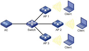
Network requirements
As shown in Figure 3, configure periodic auto-DFS to adjust channels for radios of the APs when a channel adjustment trigger condition is met. Add radio 1 of AP 1 to an RRM holddown group to avoid frequent channel adjustments.
Configuration procedure
# Establish a CAPWAP tunnel between the AC and each AP. For more information, see "Managing APs." (Details not shown.)
# Enable auto-DFS for AP ap1 and set the auto-DFS mode to periodic.
<AC> system-view
[AC] wlan ap ap1 model WA4320i-ACN
[AC-wlan-ap-ap1] radio 1
[AC-wlan-ap-ap1-radio-1] rrm
[AC-wlan-ap-ap1-radio-1-rrm] calibrate-channel self-decisive enable
[AC-wlan-ap-ap1-radio-1-rrm] calibrate-channel mode periodic
# Configure DFS trigger parameters.
[AC-wlan-ap-ap1-radio-1-rrm] crc-error-threshold 20
[AC-wlan-ap-ap1-radio-1-rrm] interference-threshold 50
[AC-wlan-ap-ap1-radio-1-rrm] tolerance-level 20
[AC-wlan-ap-ap1-radio-1-rrm] quit
[AC-wlan-ap-ap1-radio-1] quit
[AC-wlan-ap-ap1] quit
# Create RRM holddown group 10.
[AC] wlan rrm-calibration-group 10
# Add radio 1 of AP ap1 to RRM holddown group 10.
[AC-wlan-rc-group-10] ap name ap1 radio 1
# Set the channel holddown time to 600 minutes.
[AC-wlan-rc-group-10] channel holddown-time 600
# Configure auto-DFS for AP 2 and AP 3 in the same way auto-DFS is configured for AP 1. (Details not shown.)
Verifying the configuration
# Execute the display wlan rrm-status ap all command. Verify that the working channels for radios of the APs change when a channel adjustment trigger condition is met and the calibration interval is reached. (Details not shown.)
Use the display wlan rrm-history ap all command to view the channel adjustment reason. (Details not shown.)
# Verify that the channel for radio 1 on AP 1 remains unchanged within 600 minutes after the first DFS. (Details not shown.)
Scheduled auto-DFS configuration example
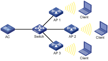
Network requirements
As shown in Figure 4, configure scheduled auto-DFS to adjust channels for radios of the APs when a channel adjustment trigger condition is met.
Configuration procedure
# Establish a CAPWAP tunnel between the AC and each AP. For more information, see "Managing APs." (Details not shown.)
# Create a time range.
<AC> system-view
[AC] time-range time1 from 15:20 2016/04/17 to 18:20 2016/04/17
# Create a job and assign commands to the job.
[AC] scheduler job calibratechannel
[AC-job-calibratechannel] command 1 system-view
[AC-job-calibratechannel] command 2 wlan ap ap1
[AC-job-calibratechannel] command 3 radio 1
[AC-job-calibratechannel] command 4 rrm
[AC-job-calibratechannel] command 5 calibrate-channel pronto
[AC-job-calibratechannel] quit
# Create a schedule and assign the job to the schedule.
[AC] scheduler schedule schedule1
[AC-schedule-schedule1] job calibratechannel
# Specify an execution date and time for the schedule.
[AC-schedule-schedule1] time at 20:20 2016/04/17
[AC-schedule-schedule1] quit
# Enable auto-DFS for AP ap1 and set the auto-DFS mode to scheduled.
[AC] wlan ap ap1
[AC-wlan-ap-ap1] radio 1
[AC-wlan-ap-ap1-radio-1] rrm
[AC-wlan-ap-ap1-radio-1-rrm] calibrate-channel self-decisive enable
[AC-wlan-ap-ap1-radio-1-rrm] calibrate-channel mode scheduled
# Configure AP ap1 to perform channel monitoring during time range time1.
[AC-wlan-ap-ap1-radio-1-rrm] calibrate-channel monitoring time-range time1
# Configure auto-DFS attributes.
[AC-wlan-ap-ap1-radio-1-rrm] crc-error-threshold 10
[AC-wlan-ap-ap1-radio-1-rrm] interference-threshold 40
[AC-wlan-ap-ap1-radio-1-rrm] tolerance-level 15
[AC-wlan-ap-ap1-radio-1-rrm] quit
# Configure auto-DFS for AP 2 and AP 3 in the same way auto-DFS is configured for AP 1. (Details not shown.)
Verifying the configuration
# Execute the display wlan rrm-status ap all command. Verify that the working channels for radios of the APs change when a channel adjustment trigger condition is met and the calibration interval is reached. (Details not shown.)
# Use the display wlan rrm-history ap all command to view the channel adjustment reason. (Details not shown.)
Periodic auto-TPC configuration example
Network requirements
As shown in Figure 5, configure periodic auto-TPC and set the adjacency factor to 3 to enable the AC to perform periodic auto-TPC when AP 4 joins. Add radio 1 of AP 1 to an RRM holddown group to avoid frequent power adjustments.
Configuration procedure
# Establish a CAPWAP tunnel between the AC and each AP. For more information, see "Managing APs." (Details not shown.)
# Enable periodic auto-TPC for AP ap1.
<AC> system-view
[AC] wlan ap ap1 model WA4320i-ACN
[AC-wlan-ap-ap1] radio 1
[AC-wlan-ap-ap1-radio-1] rrm
[AC-wlan-ap-ap1-radio-1-rrm] calibrate-power self-decisive enable
# Configure TPC trigger parameters.
[AC-wlan-ap-ap1-radio-1-rrm] adjacency-factor 3
[AC-wlan-ap-ap1-radio-1-rrm] calibrate-power threshold 80
[AC-wlan-ap-ap1-radio-1-rrm] calibrate-power min 1
[AC-wlan-ap-ap1-radio-1-rrm] quit
[AC-wlan-ap-ap1-radio-1] quit
[AC-wlan-ap-ap1] quit
# Create RRM holddown group 10.
[AC] wlan rrm-calibration-group 10
# Add radio 1 of AP ap1 to RRM holddown group 10.
[AC-wlan-rc-group-10] ap name ap1 radio 1
# Set the power holddown time to 100 minutes.
[AC-wlan-rc-group-10] power holddown-time 100
# Configure periodic auto-TPC for AP 2, AP 3, and AP 4 in the same way periodic auto-TPC is configured for AP 1. (Details not shown.)
Verifying the configuration
# Assume that the radio of AP 4 is the power-detecting radio and this step use the name of an AP to refer to its radio. Use the display wlan rrm-status ap all command to verify the following information:
· AP 1 increases its transmit power when AP 4 detects that the power of AP 1 is lower than the power adjustment threshold.
· AP 1 decreases its transmit power when AP 4 detects that the power of AP 1 is higher than the power adjustment threshold.
· The adjusted power of AP 1 is not lower than the minimum transmit power (1 dBm in this example).
# Verify that the power of radio 1 on AP 1 remains unchanged within 100 minutes after the first TPC.
Spectrum management configuration example
Network requirements
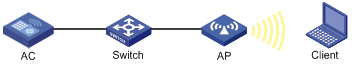
As shown in Figure 6, configure spectrum management to restrict the transmit power of the client and allow the client to continue sending frames during channel switch.
Configuration procedure
# Enable spectrum management.
<AC> system-view
[AC] wlan ap officeap model WA4320i-ACN
[AC-wlan-ap-officeap] radio 1
[AC-wlan-ap-officeap-radio-1] spectrum-management enable
# Set the channel capability match mode to all.
[AC-wlan-ap-officeap-radio-1] channel-capability mode all
# Set the transmit power capability match mode to all.
[AC-wlan-ap-officeap-radio-1] power-capability mode all
# Set the power constraint mode to manual and set the power constraint value to 5 dBm.
[AC-wlan-ap-officeap-radio-1] power-constraint mode manual 5
# Set the channel switch mode to continuous.
[AC-wlan-ap-officeap-radio-1] channel-switch mode continuous
Verifying the configuration
# Execute the display wlan client command to verify that the client can successfully associate with the radio. (Details not shown.)