- Table of Contents
-
- 02-WLAN
- 00-Preface
- 01-AP management configuration
- 02-Radio management configuration
- 03-WLAN access configuration
- 04-WLAN security configuration
- 05-WLAN authentication configuration
- 06-WIPS configuration
- 07-WLAN QoS configuration
- 08-WLAN roaming configuration
- 09-WLAN load balancing configuration
- 10-WLAN radio resource measurement configuration
- 11-Channel scanning configuration
- 12-Band navigation configuration
- 13-WLAN high availability configuration
- 14-802.11r configuration
- 15-Wireless location configuration
- 16-Hotspot 2.0 configuration
- 17-WLAN RRM configuration
- 18-WT configuration
- 19-IoT AP configuration
- 20-CM tunnel configuration
- 21-Cloud connection configuration
- 22-WLAN IP snooping configuration
- 23-WLAN fast forwarding configuration
- Related Documents
-
| Title | Size | Download |
|---|---|---|
| 16-Hotspot 2.0 configuration | 1.51 MB |
Hotspot 2.0 operating mechanism
Configuring a Hotspot 2.0 policy
Setting the access network type
Specifying a network authentication type
Configuring IP address availability
Specifying an authentication type for an NAI realm
Setting service provider information
Setting the port status for an IP protocol
Setting WAN link status parameters
Binding a Hotspot 2.0 policy to a service template
Configuring AP venue information
Setting an SSID for online signup services
Binding an OSU server to a Hotspot 2.0 policy
Displaying and maintaining Hotspot 2.0
Hotspot 2.0 configuration examples
Configuration restrictions and guidelines
Configuration restrictions and guidelines
Hotspot 2.0 configuration examples (for version 2)
Configuration restrictions and guidelines
Configuring Hotspot 2.0
Overview
Hotspot 2.0, developed by Wi-Fi Alliance, provides automatic network discovery, automated authentication, and seamless roaming for wireless clients.
Hotspot 2.0 contains two versions. Version 2 is fully compatible with version 1.
Hotspot 2.0 operating mechanism
Hotspot 2.0 operates as follows:
1. A client performs wireless scanning to discover Hotspot 2.0 networks.
2. The client exchanges Generic Advertisement Service (GAS) frames with APs to get Hotspot 2.0 information and select an optimal BSS.
3. The client performs online signup. This step is required only for version 2 of Hotspot 2.0.
Scanning
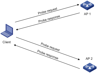
Active scanning
A wireless client periodically scans surrounding wireless networks by sending probe requests. It obtains network information from probe responses.
As shown in Figure 1, the client periodically sends a probe request on each of its supported channels to scan wireless networks. APs that receive the probe request send a probe response that carries the available wireless network information.
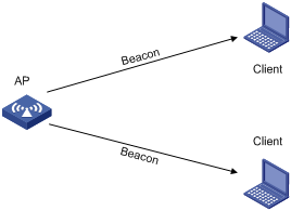
Passive scanning
As shown in Figure 2, the clients periodically listen for beacon frames sent by APs on their supported channels to get information about surrounding wireless networks. Passive scanning is used when clients want to save power.
GAS frame exchange
After discovering Hotspot 2.0 networks by active or passive scanning, a client exchanges GAS frames with APs to get APs' Hotspot 2.0 information. Based on the obtained Hotspot 2.0 information and local configuration, the client selects an optimal BSS.
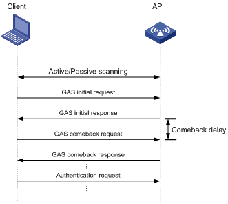
As shown in Figure 3, a client exchanges GAS frames with an AP by using the following process:
1. The client sends a GAS initial request.
2. Upon receiving the request, the AP encapsulates Hotspot 2.0 information in a GAS initial response and examines the length of the response.
¡ If the length does not exceed the limit, the AP sends the GAS initial response to the client. The GAS frame exchange is complete and the client can send an authentication request.
¡ If the length exceeds the limit, the AP fragments the response and sends the first fragment in a GAS initial response to the client. The response notifies the client to request Hotspot 2.0 information after a comeback delay.
3. The client sends a GAS comeback request to the AP after a comeback delay.
4. The AP sends a GAS comeback response that carries the second fragment to the client.
5. If the length of the response exceeds the limit, the client and the AP repeat steps 3 and 4 until all fragments are sent to the client.
Online signup
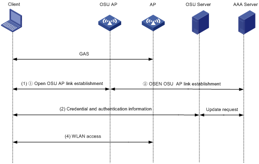
After GAS frame exchange, a client connects to the Online Sign Up (OSU) server through the OSU AP to sign up online. A signed-up client gets a credential and can automatically access a Hotspot 2.0 network without being re-authenticated. A client can associate with an OSU AP by using the following methods:
· Open OSU—No authentication.
· OSEN OSU—Layer 2 authentication.
As shown in Figure 4, online signup operates as follows:
1. The client obtains the OSU server list from the AP by exchanging GAS frames with the AP and selects an OSU server.
2. The client associates with the OSU AP through open OSU or OSEN OSU.
3. The OSU server sends a credential and authentication information to the client or updates the expired credential for the client.
4. Using the newly provisioned credential, the client disassociates from the OSU AP and associates with the AP that provides Hotspot 2.0 services.
Protocols and standards
· Wi-Fi Alliance Technical Committee Hotspot 2.0 Technical Task Group Hotspot 2.0 (Release 2)Technical Specification Version 3.04
Configuration task list
|
Tasks at a glance |
Remarks |
|
(Required.) Configuring a Hotspot 2.0 policy |
N/A |
|
(Optional.) Configuring 3GPP information |
N/A |
|
(Optional.) Setting an HESSID |
Required for version 2 of Hotspot 2.0. |
|
(Optional.) Setting the access network type |
N/A |
|
(Optional.) Specifying a network authentication type |
N/A |
|
(Optional.) Setting the domain name |
Required for version 2 of Hotspot 2.0. |
|
(Optional.) Specifying an OI |
Required for version 2 of Hotspot 2.0. |
|
(Optional.) Configuring IP address availability |
N/A |
|
(Optional.) Specifying an authentication type for an NAI realm |
N/A |
|
(Optional.) Setting service provider information |
N/A |
|
(Optional.) Setting the port status for an IP protocol |
N/A |
|
(Optional.) Setting WAN link status parameters |
N/A |
|
(Optional.) Disabling the DGAF feature |
N/A |
|
(Optional.) Managing GAS frames |
N/A |
|
(Optional.) Configuring AP venue information |
N/A |
|
(Required.) Configuring a OSU server |
Required only for version 2 of Hotspot 2.0. |
|
(Required.) Setting an SSID for online signup services |
Required only for version 2 of Hotspot 2.0. |
|
(Required.) Managing OSU server icons |
Required only for version 2 of Hotspot 2.0. |
|
(Required.) Binding an OSU server to a Hotspot 2.0 policy |
Required only for version 2 of Hotspot 2.0. |
Configuring a Hotspot 2.0 policy
A Hotspot 2.0 policy defines a set of Hotspot 2.0 parameters.
To configure a Hotspot 2.0 policy:
|
Step |
Command |
Remarks |
|
1. Enter system view. |
system-view |
N/A |
|
2. Create a Hotspot 2.0 policy and enter its view. |
By default, no Hotspot 2.0 policy exists. |
|
|
3. Specify a name for the Hotspot 2.0 policy. |
policy-name name |
By default, no name is specified for a Hotspot 2.0 policy. |
Configuring 3GPP information
The 3rd Generation Partnership Project (3GPP) information contains a country code and a network code. The country code identifies a country, and the network code identifies a service provider in the country.
To configure 3GPP information:
|
Step |
Command |
Remarks |
|
1. Enter system view. |
system-view |
N/A |
|
2. Enter service template view. |
wlan service-template service-template-name |
N/A |
|
3. Configure 3GPP information. |
3gpp-info country-code mobile-country-code network-code mobile-network-code |
By default, no country code and network code are configured. |
Setting an HESSID
A homogenous ESS identifier (HESSID) and the SSID for the extended service set (ESS) together uniquely identify a WLAN. Set the HESSID to the same value as a BSSID in the ESS.
To set an HESSID:
|
Step |
Command |
Remarks |
|
1. Enter system view. |
system-view |
N/A |
|
2. Enter Hotspot 2.0 policy view. |
N/A |
|
|
3. Set an HESSID. |
By default, no HESSID is set. |
Setting the access network type
You can set the following access network types:
· 0—Private network.
· 1—Private network with guest access.
· 2—Chargeable public network.
· 3—Free public network.
· 4—Personal device network.
· 5—Emergency services only network.
· 14—Test or experimental.
· 15—Wildcard.
To set the access network type:
|
Step |
Command |
Remarks |
|
1. Enter system view. |
system-view |
N/A |
|
2. Enter Hotspot 2.0 policy view. |
wlan hotspot-policy policy-number |
N/A |
|
3. Set the access network type. |
By default, no access network type is set. |
Specifying a network authentication type
You can specify the following network authentication types:
· 0—Acceptance of terms and conditions.
· 1—On-line enrollment.
· 2—HTTP/HTTPS redirection.
· 3—DNS redirection.
To specify a network authentication type:
|
Step |
Command |
Remarks |
|
1. Enter system view. |
system-view |
N/A |
|
2. Enter Hotspot 2.0 policy view. |
wlan hotspot-policy policy-number |
N/A |
|
3. Specify a network authentication type. |
authentication-type { 0 [ redirect-url redirect-url ] | 1 | 2 redirect-url redirect -url | 3 } |
By default, no network authentication type is specified. |
Setting the domain name
|
Step |
Command |
Remarks |
|
1. Enter system view. |
system-view |
N/A |
|
2. Enter Hotspot 2.0 policy view. |
wlan hotspot-policy policy-number |
N/A |
|
3. Set the domain name. |
domain-name domain-name |
By default, the domain name is not set. |
Specifying an OI
An organization identifier (OI) identifies a roaming consortium. If a client has the certificate to a roaming consortium, the client can roam to all wireless services provided by the roaming consortium.
To specify an OI:
|
Step |
Command |
Remarks |
|
1. Enter system view. |
system-view |
N/A |
|
2. Enter Hotspot 2.0 policy view. |
wlan hotspot-policy policy-number |
N/A |
|
3. Specify an OI. |
roam-oi oi [ in-beacon ] |
By default, no OI is specified. |
Configuring IP address availability
Perform this task to configure IP address availability. IP address availability specifies the version and type of IP addresses that an AP assigns to associated clients.
· IPv4 address availability.
¡ 0—Address type not available.
¡ 1—Public IPv4 address available.
¡ 2—Port-restricted IPv4 address available.
¡ 3—Single NATed private IPv4 address available.
¡ 4—Double NATed private IPv4 address available.
¡ 5—Port-restricted IPv4 address and single NATed IPv4 address available.
¡ 6—Port-restricted IPv4 address and double NATed IPv4 address available.
¡ 7—Availability of the address type is not known.
· IPv6 address availability.
¡ 0—Address type not available.
¡ 1—Address type available.
¡ 2—Availability of the address type not known.
To configure IP address availability:
|
Step |
Command |
Remarks |
|
1. Enter system view. |
system-view |
N/A |
|
2. Enter Hotspot 2.0 policy view. |
wlan hotspot-policy policy-number |
N/A |
|
3. Configure IP address availability. |
ip-type ipv4 ipv4-type ipv6 ipv6-type |
By default, the availability is 1 for an IPv4 address and 2 for an IPv6 address. |
Specifying an authentication type for an NAI realm
|
Step |
Command |
Remarks |
|
1. Enter system view. |
system-view |
N/A |
|
2. Enter Hotspot 2.0 policy view. |
wlan hotspot-policy policy-number |
N/A |
|
3. Create an NAI realm and specify an authentication type for the NAI realm. |
nai-realm realm-name eap-method eap-method-id auth-method auth-method-id authentication authentication |
By default, no NAI realm is created. |
Setting service provider information
|
Step |
Command |
Remarks |
|
1. Enter system view. |
system-view |
N/A |
|
2. Enter Hotspot 2.0 policy view. |
wlan hotspot-policy policy-number |
N/A |
|
3. Set service provider information. |
operator-name operator-name lang-code lang-code |
By default, no service provider information is set. |
Setting the port status for an IP protocol
|
Step |
Command |
Remarks |
|
1. Enter system view. |
system-view |
N/A |
|
2. Enter Hotspot 2.0 policy view. |
wlan hotspot-policy policy-number |
N/A |
|
3. Set the port status for an IP protocol. |
ip-protocol { esp | icmp | tcp | udp } port-number port-number { closed | open | unknown } |
By default, no port status is set for an IP protocol. |
Setting WAN link status parameters
This feature enables Hotspot 2.0 to advertise uplink and downlink speeds and link status such as closed, testing, and enabled of the WAN.
To set WAN link status parameters:
|
Step |
Command |
Remarks |
|
1. Enter system view. |
system-view |
N/A |
|
2. Enter Hotspot 2.0 policy view. |
wlan hotspot-policy policy-number |
N/A |
|
3. Set WAN link status parameters. |
wan-metrics { link-down | link-test | link-up } [ asymmetric downlink-speed downlink-speed uplink-speed uplink-speed | symmetric link-speed link-speed ] |
By default, no WAN link status parameters are set. |
Disabling the DGAF feature
The Downstream Group-Addressed Forwarding (DGAF) feature enables an AP to forward all downstream wireless broadcast ARP packets and wireless multicast packets. To prevent spoofing attacks by using downstream multicasts, you can disable the DGAF feature for the AP.
To avoid packet loss, enable proxy ARP and multicast optimization before disabling DGAF. For more information about proxy ARP, see Layer 3—IP Services Configuration Guide.
To disable the DGAF feature:
|
Step |
Command |
Remarks |
|
1. Enter system view. |
system-view |
N/A |
|
2. Enter Hotspot 2.0 policy view. |
wlan hotspot-policy policy-number |
N/A |
|
3. Disable the DGAF feature. |
undo dgaf enable |
By default, the DGAF feature is enabled. Before disabling DGAF, make sure all service templates bound to the Hotspot 2.0 policy are disabled. |
Managing GAS frames
|
Step |
Command |
Remarks |
|
1. Enter system view. |
system-view |
N/A |
|
2. Enter Hotspot 2.0 policy view. |
wlan hotspot-policy policy-number |
N/A |
|
3. Set the comeback delay. |
comeback-delay value |
By default, the comeback delay is 1 TU (1024 milliseconds). The comeback delay prevents clients from frequently sending GAS comeback requests. |
|
4. Set the maximum number of GAS initial requests that clients can send within the specified interval. |
gas-limit number number interval interval |
By default, the number of GAS initial requests that clients can send is not limited. This command can ease the AC's burden. |
Binding a Hotspot 2.0 policy to a service template
Before you bind a Hotspot 2.0 policy to a service template, make sure the following settings are configured for the service template:
· 802.1X authentication and key management mode.
· RSN IE.
· AES-CCMP cipher suite.
To bind a Hotspot 2.0 policy to a service template:
|
Step |
Command |
Remarks |
|
1. Enter system view. |
system-view |
N/A |
|
2. Enter service template view. |
wlan service-template service-template-name |
N/A |
|
3. Bind a Hotspot 2.0 policy to the service template. |
hotspot-policy policy-number |
By default, no Hotspot 2.0 policy is bound to a service template. |
Configuring AP venue information
AP venue information indicates the location of APs and helps clients connect to an optimal AP.
To configure AP venue information:
|
Step |
Command |
Remarks |
|
1. Enter system view. |
system-view |
N/A |
|
2. Enter AP view. |
N/A |
|
|
3. Specify the venue group and venue type for the AP. |
venue group venue-group-number type venue-type-number |
By default, no venue group and venue type are specified for an AP. |
|
4. Set a venue name for the AP. |
By default, no venue name is set for an AP. |
Configuring a OSU server
This task is required only for version 2 of Hotspot 2.0.
To configure an OSU server:
|
Step |
Command |
Remarks |
|
1. Enter system view. |
system-view |
N/A |
|
2. Create an OSU server and enter its view, or enter the view of an existing OSU server. |
wlan osu-provider osu-provider-number |
By default, no OSU server exists. |
|
3. Set a name for the OSU server. |
friendly-name friendly-name lang-code lang-code |
By default, no name is set for an OSU server. |
|
4. Specify the URI of the OSU server. |
uri uri |
By default, no URI is specified for an OSU server. |
|
5. Specify a protocol for clients to communicate with the OSU server. |
method method-id |
By default, no method is specified for clients to communicate with an OSU server. |
|
6. Specify an icon for the OSU server. |
icon-file filename lang-code lang-code icon-type icon-type |
By default, no icon is specified for an OSU server. Before specifying an icon for an OSU server, make sure directory icon has been created by using the mkdir command in the root directory where the version files are saved. Then use FTP or TFTP to download icon files to the directory. |
|
7. (Optional.) Configure a description for the OSU server. |
description description lang-code lang-code |
By default, no description is configured for an OSU server. |
|
8. (Optional.) Configure a Network Access Identifier (NAI) for the OSU server. |
nai nai |
By default, no NAI is configured for an OSU server. |
Setting an SSID for online signup services
This task is required only for version 2 of Hotspot 2.0.
Hotspot 2.0 provides different SSIDs for online signup services and wireless services.
Make sure the configured SSID for online signup services is the same as the SSID for the online signup service template.
To set an SSID for online signup services:
|
Step |
Command |
Remarks |
|
1. Enter system view. |
system-view |
N/A |
|
2. Enter Hotspot 2.0 policy view. |
wlan hotspot-policy policy-number |
N/A |
|
3. Set an SSID for online signup services. |
osu-ssid ssid-name |
By default, no SSID is set for online signup services. |
Managing OSU server icons
This task is required only for version 2 of Hotspot 2.0.
Perform this task to load all icon files specified for an OSU server to validate the changes when icon file changes occur or to invalidate icon files.
To manage an OSU server icon:
|
Step |
Command |
|
|
1. Enter system view. |
system-view |
|
|
2. Manage OSU server icon files. |
· Load OSU server icon files: · Unload OSU server icon files: |
|
Binding an OSU server to a Hotspot 2.0 policy
This task is required only for version 2 of Hotspot 2.0.
A Hotspot 2.0 policy can be bound to a maximum of 32 OSU servers.
Make sure all configuration required for an OSU server has been completed before binding the OSU server to a Hotspot 2.0 policy.
To bind an OSU server to a Hotspot 2.0 policy:
|
Step |
Command |
Remarks |
|
1. Enter system view. |
system-view |
N/A |
|
2. Enter Hotspot 2.0 policy view. |
wlan hotspot-policy policy-number |
N/A |
|
3. Bind an OSU server to the Hotspot 2.0 policy. |
osu-provider osu-provider-number |
By default, no OSU server is bound to a Hotspot 2.0 policy. |
Displaying and maintaining Hotspot 2.0
Execute display commands in any view.
|
Command |
|
|
Display service template information. |
display wlan service-template [ service-template-name ] [ verbose ] |
|
Display all the loaded OSU server icon files. |
display wlan hotspot uploaded-osu-icon |
Hotspot 2.0 configuration examples
iPhone application
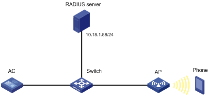
Network requirements
As shown in Figure 5, configure Hotspot 2.0 to enable the phone to switch from the cellular network to the wireless network.

Configuration restrictions and guidelines
Make sure you have installed certificates and created a user account on the RADIUS server, so that client authentication, authorization, and accounting can operate correctly.
For more information about AAA, see Security Configuration Guide.
Configuration procedures
Configuring the AC
1. Configure a Hotspot 2.0 policy:
# Create the Hotspot 2.0 policy 1.
<AC> system-view
[AC] wlan hotspot-policy 1
# Configure EAP-TLS authentication.
[AC-wlan-hs-1] nai-realm h3c.com eap-method 6 auth-method 2 authentication 4
# Set the domain name to h3c.com.
[AC-wlan-hs-1] domain-name h3c.com
# Set the HESSID to 1232-ff23-0123.
[AC-wlan-hs-1] hessid 1232-ff23-0123
[AC-wlan-hs-1] quit
2. Configure 802.1X authentication and the RADIUS scheme:
# Configure the 802.1X authentication method as EAP.
[AC] dot1x authentication-method eap
# Create RADIUS scheme imcc.
[AC] radius scheme imcc
# Set the IP address and the port number of the primary authentication server to 10.18.1.88 and 1812, respectively.
[AC-radius-imcc] primary authentication 10.18.1.88 1812
# Set the IP address and the port number of the primary accounting server to 10.18.1.88 and 1813, respectively.
[AC-radius-imcc] primary accounting 10.18.1.88 1813
# Set the shared key for the AC to exchange packets with the authentication and accounting servers to 12345678.
[AC-radius-imcc] key authentication simple 12345678
[AC-radius-imcc] key accounting simple 12345678
# Configure the AC to remove the domain name in the username sent to the RADIUS servers.
[AC-radius-imcc] user-name-format without-domain
[AC-radius-imcc] quit
3. Create the domain imc and configure the domain to use the RADIUS scheme imcc for authentication, authorization, and accounting.
[AC] domain imc
[AC-isp-imc] authentication lan-access radius-scheme imcc
[AC-isp-imc] authorization lan-access radius-scheme imcc
[AC-isp-imc] accounting lan-access radius-scheme imcc
[AC-isp-imc] quit
Configuring the AP
# Create the service template service1.
<AC> system-view
[AC] wlan service-template service1
# Set the SSID to service.
[AC-wlan-st-service1] ssid service
# Bind the Hotspot 2.0 policy 1 to the service template.
[AC-wlan-st-service1] hotspot-policy 1
# Enable the RSN IE in beacons and probe responses.
[AC-wlan-st-service1] security-ie rsn
# Enable the AES-CCMP cipher suite.
[AC-wlan-st-service1] cipher-suite ccmp
# Set the authentication and key management mode to 802.1X.
[AC-wlan-st-service1] akm mode dot1x
# Set the authentication mode for WLAN clients to 802.1X.
[AC-wlan-st-service1] client-security authentication-mode dot1x
# Specify the domain imc as the authentication domain.
[AC-wlan-st-service1] dot1x domain imc
# Enable the service template.
[AC-wlan-st-service1] service-template enable
[AC-wlan-st-service1] quit
# Create the AP ap1, and specify the AP model and serial ID.
[AC] wlan ap ap1 model WA4320i-ACN
[AC-wlan-ap-ap1] serial-id 219801A0CNC138011454
# Bind the service template service1 to radio 2 of the AP.
[AC-wlan-ap-ap1] radio 2
[AC-wlan-ap-ap1-radio-2] radio enable
[AC-wlan-ap-ap1-radio-2] service-template service1
[AC-wlan-ap-ap1-radio-2] quit
[AC-wlan-ap-ap1] quit
Configuring the RADIUS server (IMCv7)
This example was created on IMC PLAT 7.1 and IMC UAM 7.1.
To configure the IMC server:
1. Log in to the IMC platform.
2. Click the User tab.
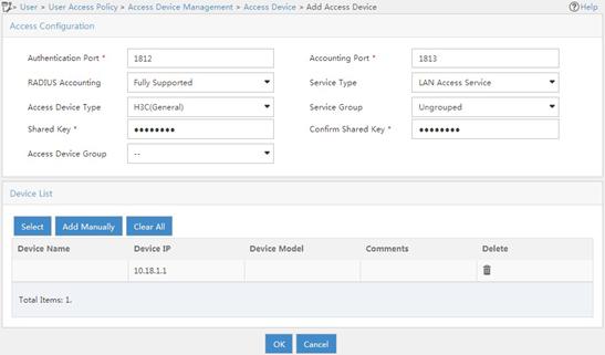
3. Add an access device:
a. From the navigation tree, select User Access Policy > Access Device Management > Access Device.
b. On the access device configuration page, click Add.
c. On the Add Access Device page, configure the following parameters:
- Set the shared key to 12345678.
- Select or manually add the device with the IP address 10.18.1.1 (IP address of the AC).
- Use the default settings for other parameters.
d. Click OK.
Figure 6 Adding an access device
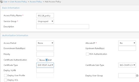
4. Add an access policy:
a. From the navigation tree, select User Access Policy > Access Policy.
b. On the access policy configuration page, click Add.
c. On the Add Access Policy page, configure the following parameters:
- Set the access policy name to 802.1X_policy.
- Select EAP-PEAP Authentication from the Certificate Type list, and from the Certificate Sub-Type list, select the certificate sub-type, which must be the same as the authentication method for the client.
- Use the default settings for other parameters.
Figure 7 Adding an access policy
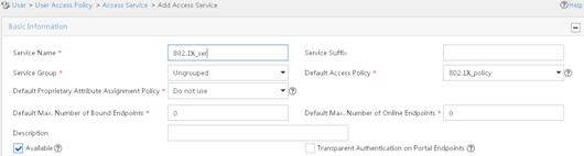
5. Add an access service:
a. From the navigation tree, select User Access Policy > Access Service.
b. On the access service configuration page, click Add.
c. On the Add Access Service page, configure the service name as 802.1X_ser, and use the 802.1X policy you have created as the default access policy.
d. Use the default settings for other parameters.
Figure 8 Adding an access service
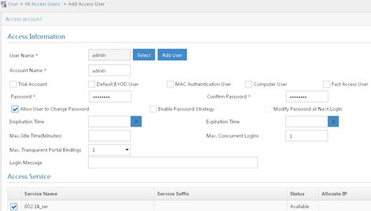
6. Add an access user:
a. From the navigation tree, select Access User > All Access Users.
b. On the access user configuration page, click Add.
c. On the Add Access User page, click Add User.
d. On the Add User window, configure the following parameters:
- Set the username to admin.
- Set the account name to admin.
- Select the 802.1X user 802.1X_ser you have configured in the Access Service area..
Figure 9 Adding an access user
Configuring the phone
This example was created using an iPhone 5S.
To configure the phone:
1. Install the Apple Configurator App on the MacBook Air and connect iPhone 5S to the laptop.
Figure 10 Apply Configurator App

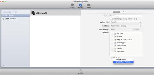
2. Open the Apple Configurator App and select Supervise from the top menu. Then click + under the Profiles list and select Create New Profile.
Figure 11 Creating a new profile
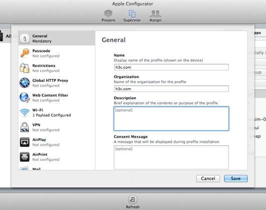
3. Click General on the left navigation tree, and enter h3c.com in the Name field. Other parameters are optional.
Figure 12 General settings
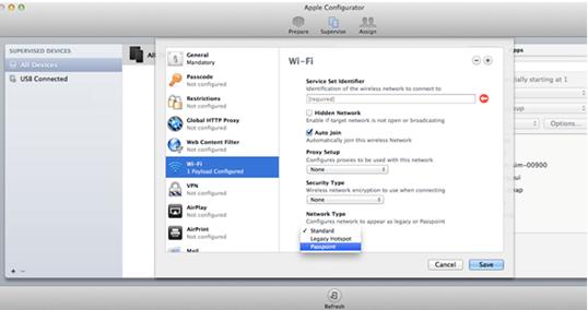
4. Click Wi-Fi on the left navigation tree and click Configure from the menu. Then select Passpoint from the Network Type list.
Figure 13 Enabling passpoint
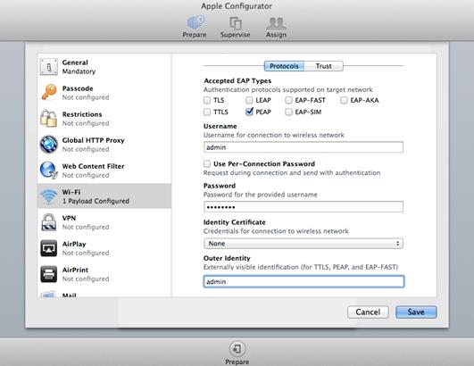
5. On the page that appears, perform the following tasks:
¡ In the Accepted EAP Types area, select PEAP.
¡ Enter admin and 12345678 in the Username area and Password area, respectively.
¡ Select None from the Identity Certificate list.
¡ Enter admin in the Outer Identity area.
Figure 14 Configuring EAP-PEAP authentication
¡ Enter h3c.com in the Provider Display Name field and enter the domain name that you have configured in the hotspot policy on the AC.
Figure 15 Configuring the domain name
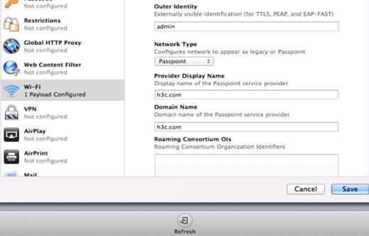
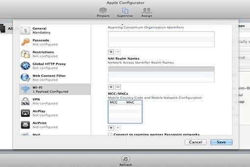
¡ Leave Roaming Consortium Ols, NAI Real Names, and MCC/MNC blank, or enter the values you have configured in the hotspot policy on the AC. Then click Save.
Figure 16 Configuring other options
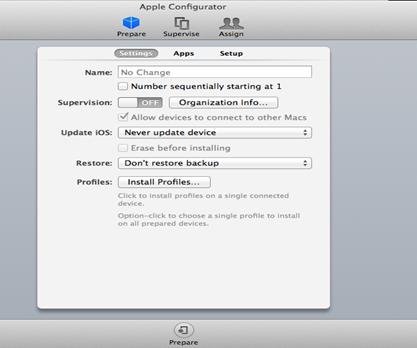
6. Click Prepare and then click Install Profiles on the Settings tab.
Figure 17 Installing profiles
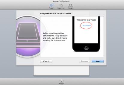
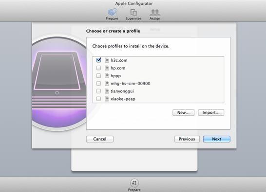
7. Click Next.
Figure 18 Installing profiles
8. Select the profile h3c.com and click Next.
Figure 19 Selecting the created profile
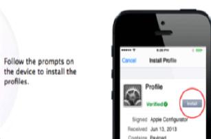
9. Click Install.
Figure 20 Installing the profile
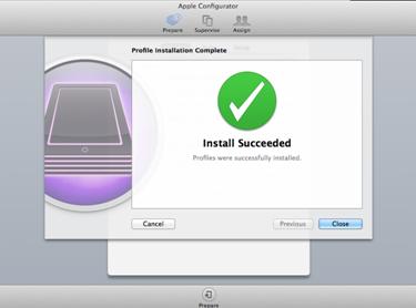
After the installation is complete, the Apple Configurator page displays Install Succeeded and all configuration will be deployed to iPhone 5S. When the phone finds the service it needs, it automatically joins the WLAN.
Figure 21 Installation complete
Verifying the configuration
# Verify that the phone can automatically connect to the WLAN service.
[AC] display wlan client verbose
Total number of clients: 1
MAC address : 6021-c05d-19e0
IPv4 address : 105.0.0.5
IPv6 address : N/A
Username : dongxixi
AID : 1
AP ID : 2
AP name : ap1
Radio ID : 2
SSID : dongxixi
BSSID : 70f9-6dd7-cfd0
VLAN ID : 1
Sleep count : 0
Wireless mode : 802.11gn
Channel bandwidth : 20MHz
SM power save : Enabled
SM power save mode : Static
Short GI for 20MHz : Supported
Short GI for 40MHz : Not supported
STBC RX capability : Not supported
STBC TX capability : Not supported
LDPC RX capability : Not supported
Block Ack : TID 0 In
Support HT-MCS set : 0, 1, 2, 3, 4, 5, 6, 7
Supported rates : 1, 2, 5.5, 6, 9, 11,
12, 18, 24, 36, 48, 54 Mbps
QoS mode : WMM
Listen interval : 10
RSSI : 49
Rx/Tx rate : 1/72.2 Mbps
Authentication method : Open system
Security mode : RSN
AKM mode : 802.1X
Cipher suite : CCMP
User authentication mode : 802.1X
Authorization ACL ID : N/A
Authorization user profile : N/A
Roam status : N/A
Key derivation : SHA1
PMF status : N/A
Forwarding policy name : N/A
Online time : 0days 0hours 0minutes 36seconds
FT status : Inactive
Samsung application
Network requirements
As shown in Figure 22, configure Hotspot 2.0 to enable the phone to switch from the cellular network to the wireless network.
Configuration restrictions and guidelines
When you configure Hotspot 2.0, follow these restrictions and guidelines:
· Make sure you have installed certificates and created a user account on the RADIUS server, so that client authentication, authorization, and accounting can operate correctly.
· Make sure you have configured 802.1X and installed the certificate on the phone.
· For more information about AAA, see Security Configuration Guide.
Configuration procedures
Configuring the AC
1. Configure the Hotspot 2.0 policy:
# Create the Hotspot 2.0 policy 1.
[AC] wlan hotspot-policy 1
# Configure EAP-TLS authentication.
[AC-wlan-hs-1] nai-realm abc.com eap-method 6 auth-method 2 authentication 4
# Set the domain name to domain.abc.com.
[AC-wlan-hs-1] domain-name domain.abc.com
# Set the HESSID to 1232-ff23-0123, the MAC address of the AP.
[AC-wlan-hs-1] hessid 1232-ff23-0123
[AC-wlan-hs-1] quit
2. Configure 802.1X authentication and the RADIUS scheme:
# Configure the 802.1X authentication method as EAP.
[AC] dot1x authentication-method eap
# Create the RADIUS scheme imcc.
[AC] radius scheme imcc
# Set the IP address and the port number of the primary authentication server to 10.18.1.88 and 1812, respectively.
[AC-radius-imcc] primary authentication 10.18.1.88 1812
# Set the IP address and the port number of the primary accounting server to 10.18.1.88 and 1813, respectively.
[AC-radius-imcc] primary accounting 10.18.1.88 1813
# Set the shared key for the AC to exchange packets with the authentication and accounting servers to 12345678.
[AC-radius-imcc] key authentication simple 12345678
[AC-radius-imcc] key accounting simple 12345678
# Configure the AC to remove the domain name in the username sent to the RADIUS servers.
[AC-radius-imcc] user-name-format without-domain
[AC-radius-imcc] quit
3. Create the domain imc and configure the domain to use the RADIUS scheme imcc for authentication, authorization, and accounting.
[AC-isp-imc] authentication lan-access radius-scheme imcc
[AC-isp-imc] authorization lan-access radius-scheme imcc
[AC-isp-imc] accounting lan-access radius-scheme imcc
[AC-isp-imc] quit
Configuring the AP
# Create the service template service1.
[AC] wlan service-template service1
# Set the SSID to service.
[AC-wlan-st-service1] ssid service
# Bind the Hotspot 2.0 policy 1 to the service template.
[AC-wlan-st-service1] hotspot-policy 1
# Enable the RSN IE in beacons and probe responses.
[AC-wlan-st-stname] security-ie rsn
# Enable the AES-CCMP cipher suite.
[AC-wlan-st-service1] cipher-suite ccmp
# Set the authentication and key management mode to 802.1X.
[AC-wlan-st-service1] akm mode dot1x
# Set the authentication mode for WLAN clients to 802.1X.
[AC-wlan-st-service1] client-security authentication-mode dot1x
# Specify the domain imc as the authentication domain.
[AC-wlan-st-service1] dot1x domain imc
# Enable the service template.
[AC-wlan-st-service1] service-template enable
[AC-wlan-st-service1] quit
# Create the AP ap1, and specify the AP model and serial ID.
[AC] wlan ap ap1 model WA4320i-ACN
[AC-wlan-ap-ap1] serial-id 219801A0CNC138011454
# Bind the service template service1 to radio 2 of the AP.
[AC-wlan-ap-ap1-radio-2] radio enable
[AC-wlan-ap-ap1-radio-2] service-template service1
[AC-wlan-ap-ap1-radio-2] quit
[AC-wlan-ap-ap1] quit
Configuring the RADIUS server (IMCv7)
This example was created on IMC PLAT 7.1 and IMC UAM 7.1.
To configure the IMC server:
1. Log in to the IMC platform.
2. Click the User tab.
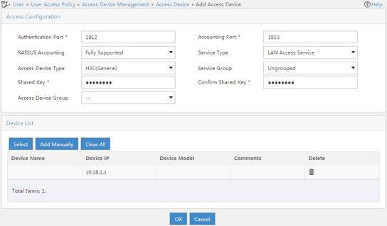
3. Add an access device:
a. From the navigation tree, select User Access Policy > Access Device Management > Access Device.
b. On the access device configuration page, click Add.
c. On the Add Access Device page, configure the following parameters:
- Set the shared key to 12345678.
- Select or manually add the device with the IP address 10.18.1.1 (IP address of the AC).
- Use the default settings for other parameters.
d. Click OK.
Figure 23 Adding an access device
4. Add an access policy:
a. From the navigation tree, select User Access Policy > Access Policy.
b. On the access policy configuration page, click Add.
c. On the Add Access Policy page, configure the following parameters:
- Set the access policy name to 802.1X_policy.
- Select EAP-PEAP Authentication from the Certificate Type list, and from the Certificate Sub-Type list, select the certificate sub-type, which must be the same as the authentication method for the client.
- Use the default settings for other parameters.
Figure 24 Adding an access policy

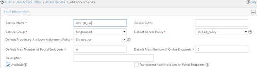
5. Add an access service:
a. From the navigation tree, select User Access Policy > Access Service.
b. On the access service configuration page, click Add.
c. On the Add Access Service page, configure the service name as 802.1X_ser, and use the 802.1X policy you have created as the default access policy.
d. Use the default settings for other parameters.
Figure 25 Adding an access service
6. Add an access user:
a. From the navigation tree, select Access User > All Access Users.
b. On the access user configuration page, click Add.
c. On the Add Access User page, click Add User.
d. On the Add User window, configure the following parameters:
- Set the username to admin.
- Set the account name to admin.
- Select the 802.1X user 802.1X_ser you have configured in the Access Service area..
Figure 26 Adding an access user

Configuring the phone
|
|
IMPORTANT: · Configure the same realm name and domain for both the phone and the Hotspot 2.0 policy on the AC. · Configure the same username and password for both the phone and the RADIUS server. · Configure the same authentication type for the phone, the Hotspot 2.0 policy on the AC, and the RADIUS server. |
This example was created using Samsung S4.
To configure the phone:
1. Use a text editor to edit the Hotspot 2.0 configuration file and save it with the name cred.conf on a PC or on the phone.
realm="abc.com"
username="admin"
password="12345678"
domain="domain.abc.com"
eap=PEAP
phase2="auth=MSCHAPV2"
}
2. Save the configuration file in the root directory of the phone:
¡ If you edit the configuration file on a PC, use either of the following methods to import the configuration file to the phone and save it in the root directory:
- Connect the phone to a PC by using a USB cable, and save the file cred.conf in the phone.
- Send an email to the phone with the file cred.conf attached and save the file in the phone.
¡ If you edit the file on the phone by using a text editor, save it in the root directory of the phone.
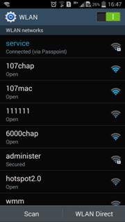
3. Turn on WLAN on the phone.
Figure 27 Turning on WLAN
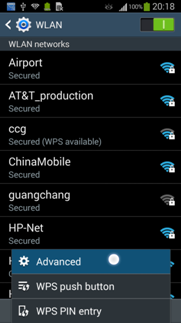
4. Click Advanced.
Figure 28 Configuring advanced WLAN settings
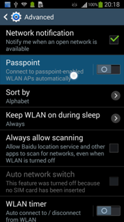
5. On the Advanced page, enable Passpoint.
Figure 29 Enabling Passpoint
Verifying the configuration
# Verify that the phone can automatically connect to the WLAN service.
[AC] display wlan client verbose
Total number of clients: 1
MAC address : 000f-e265-6400
IPv4 address : 10.1.1.114
IPv6 address : 2001::1234:5678:0102:0304
Username : admin
AP ID : 1
AP name : ap1
Radio ID : 1
SSID : service
BSSID : 0026-3e08-1150
VLAN ID : 1
Power save mode : Active
Wireless mode : 802.11gn
Channel bandwidth : 20MHz
SM power save : Disabled
Short GI for 20MHz : Not supported
Short GI for 40MHz : Supported
Support MCS set : 0, 1, 2, 3, 4, 5, 6, 7, 8, 9, 10
Block Ack (TID 0) : In
QoS mode : N/A
Listen interval : 10
RSSI : 62
Rx/Tx rate : 130/11 Mbps
Authentication method : Open system
Hotspot 2.0 configuration examples (for version 2)
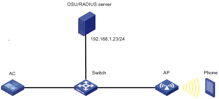
Network requirements
As shown in Figure 30, configure Hotspot 2.0 to enable the phone to switch from the cellular network to the wireless network.
Configuration restrictions and guidelines
When you configure Hotspot 2.0, follow these restrictions and guidelines:
· For more information about AAA, see Security Configuration Guide.
· Before uploading the OSU server icon, make sure the icon file is in the root directory where the version files are saved. You can use FTP or TFTP to transmit the icon file.
Configuration procedures
1. Configure the OSU server:
# Create OSU server 1.
<AC> system-view
[AC] wlan osu-provider 1
# Set the name for the OSU server to osu_test.
[AC-wlan-osu-1] friendly-name osu_test lang-code eng
# Specify a URI for the OSU server.
[AC-wlan-osu-1] uri https://192.168.1.23:8088/service
# Set the protocol for clients to communicate with the OSU server to SOAP-XML SPP.
[AC-wlan-osu-1] method 1
# Specify an icon for the OSU server.
[AC-wlan-osu-1] icon-file test.png lang-code eng icon-type png
# Configure a description for the OSU server.
[AC-wlan-osu-1] description "The OSU provider." lang-code eng
# Configure the NAI.
[AC-wlan-osu-1] nai example.com
[AC-wlan-osu-1] quit
2. Configure a Hotspot 2.0 policy:
# Create Hotspot 2.0 policy 1.
[AC] wlan hotspot-policy 1
# Specify the authentication type for NAI realm example.com.
[AC-wlan-hs-1] nai-realm example.com eap-method 5 auth-method 2 authentication 4
# Set the access network type to Wildcard.
[AC-wlan-hs-1] network-type 15
# Set the OI to 80F62E and add the OI to beacons.
[AC-wlan-hs-1] roam-oi 80F62E in-beacon
# Set the domain name to domain.com.
[AC-wlan-hs-1] domain-name domain.com
# Set the availability to 1 for both IPv4 addresses and IPv6 addresses.
[AC-wlan-hs-1] ip-type ipv4 1 ipv6 1
# Set the SSID for online signup services to osu-ssid.
[AC-wlan-hs-1] osu-ssid osu-ssid
# Bind OSU server 1 to Hotspot 2.0 policy 1.
[AC-wlan-hs-1] osu-provider 1
[AC-wlan-hs-1] quit
# Upload the specified OSU server icons if a specified icon file changes.
[AC] wlan hotspot osu-icon upload
3. Configure a service template for online signup services:
# Create service template osu.
[AC] wlan service-template osu
# Set the SSID to osu-ssid.
[AC-wlan-st-osu] ssid osu-ssid
# Enable the service template.
[AC-wlan-st-osu] service-template enable
[AC-wlan-st-osu] quit
4. Configure 802.1X authentication and the RADIUS server:
# Configure the 802.1X authentication method as EAP.
[AC] dot1x authentication-method eap
# Create RADIUS scheme imcc.
# Set the IP address and the port number of the primary authentication server to 192.168.1.23 and 1813, respectively.
[AC-radius-imcc] primary authentication 192.168.1.23 1812
# Set the IP address and the port number of the primary accounting server to 192.168.1.23 and 1813, respectively.
[AC-radius-imcc] primary accounting 192.168.1.23 1813
# Set the shared key for the AC to exchange packets with the authentication and accounting server to 12345678.
[AC-radius-imcc] key authentication simple 12345678
[AC-radius-imcc] key accounting simple 12345678
# Configure the AC to remove the domain name in the username sent to the RADIUS servers.
[AC-radius-imcc] user-name-format without-domain
[AC-radius-imcc] quit
5. Configure ISP domain:
# Create domain imc and configure the domain to use RADIUS scheme imcc for authentication, authorization, and accounting.
[AC-isp-imc] authentication lan-access radius-scheme imcc
[AC-isp-imc] authorization lan-access radius-scheme imcc
[AC-isp-imc] accounting lan-access radius-scheme imcc
[AC-isp-imc] quit
6. Configure a service template for wireless services:
# Create service template stname.
[AC] wlan service-template stname
# Set the SSID to service.
[AC-wlan-st-stname] ssid service
# Bind Hotspot 2.0 policy 1 to the service template.
[AC-wlan-st-stname] hotspot-policy 1
# Enable the RSN IE in beacons and probe responses.
[AC-wlan-st-stname] security-ie rsn
# Enable the AES-CCMP cipher suite.
[AC-wlan-st-stname] cipher-suite ccmp
[AC-wlan-st-stname] akm mode dot1x
# Set the authentication mode for WLAN clients to 802.1X.
[AC-wlan-st-stname] client-security authentication-mode dot1x
# Specify the domain imc as the authentication domain.
[AC-wlan-st-stname] dot1x domain imc
# Enable the service template.
[AC-wlan-st-stname] service-template enable
[AC-wlan-st-stname] quit
7. Configure the AP:
# Create AP ap1, and specify the AP model and serial ID.
[AC] wlan ap ap1 model WA4320i-ACN
[AC-wlan-ap-ap1] serial-id 210235A1BSC123000050
# Set a venue name for the AP.
[AC-wlan-ap-ap1] venue name "H3C lab" lang-code eng
# Bind service template stname to radio 2 of the AP.
[AC-wlan-ap-ap1] radio 2
[AC-wlan-ap-ap1-radio-2] radio enable
[AC-wlan-ap-ap1-radio-2] service-template stname
[AC-wlan-ap-ap1-radio-2] service-template osu
[AC-wlan-ap-ap1-radio-2] quit
[AC-wlan-ap-ap1] quit
Verifying the configuration
# Verify that the OSU server icon has been loaded.
[AC] display wlan hotspot uploaded-osu-icon
Total number of icons: 1
Icon name Icon type
--------------------------------------------------------------------------------
test.png png
# Verify that the phone can automatically connect to the WLAN service.
[AC] display wlan client verbose
Total number of clients: 1
MAC address : d022-bee8-a267
IPv4 address : 192.168.1.52
IPv6 address : N/A
Username : abcd
AID : 2
AP ID : 1
AP name : ap1
Radio ID : 2
SSID : service
BSSID : 5866-ba74-e790
VLAN ID : 1
Sleep count : 37
Wireless mode : 802.11gn
Channel bandwidth : 20MHz
SM power save : Disabled
Short GI for 20MHz : Supported
Short GI for 40MHz : Not supported
STBC RX capability : Supported
STBC TX capability : Not supported
LDPC RX capability : Not supported
Block Ack : TID 0 Both
TID 2 Out
Supported HT MCS set : 0, 1, 2, 3, 4, 5, 6, 7
Supported rates : 1, 2, 5.5, 6, 9, 11,
12, 18, 24, 36, 48, 54 Mbps
QoS mode : WMM
Listen interval : 10
RSSI : 45
Rx/Tx rate : 72.2/72.2 Mbps
Authentication method : Open system
Security mode : RSN
AKM mode : 802.1X
Cipher suite : CCMP
User authentication mode : 802.1X
Authorization ACL ID : N/A
Authorization user profile : N/A
Roam status : N/A
Key derivation : SHA1
PMF status : N/A
Forwarding policy name : N/A
Online time : 0days 0hours 1minutes 29seconds
FT status : Inactive