- Table of Contents
-
- 02-WLAN
- 00-Preface
- 01-AP management configuration
- 02-Radio management configuration
- 03-WLAN access configuration
- 04-WLAN security configuration
- 05-WLAN authentication configuration
- 06-WIPS configuration
- 07-WLAN QoS configuration
- 08-WLAN roaming configuration
- 09-WLAN load balancing configuration
- 10-WLAN radio resource measurement configuration
- 11-Channel scanning configuration
- 12-Band navigation configuration
- 13-WLAN high availability configuration
- 14-802.11r configuration
- 15-Wireless location configuration
- 16-Hotspot 2.0 configuration
- 17-WLAN RRM configuration
- 18-WT configuration
- 19-IoT AP configuration
- 20-CM tunnel configuration
- 21-Cloud connection configuration
- 22-WLAN IP snooping configuration
- 23-WLAN fast forwarding configuration
- Related Documents
-
| Title | Size | Download |
|---|---|---|
| 04-WLAN security configuration | 362.22 KB |
Contents
WLAN security configuration task lists
Setting the security information element
Setting the TKIP MIC failure hold time
Configuring management frame protection
Enabling the dynamic WEP mechanism
Enabling SNMP notifications for WLAN security
Displaying and maintaining WLAN security
WLAN security configuration examples
Shared key authentication configuration example
PSK authentication and bypass authentication configuration example
PSK authentication and MAC authentication configuration example
802.1X AKM configuration example
Management frame protection configuration example
Dynamic WEP mechanism configuration example
Private PSK authentication and MAC authentication configuration example
Configuring WLAN security
Overview
The original IEEE 802.11 is a Pre Robust Security Network Association (Pre-RSNA) mechanism. This mechanism is vulnerable to security attacks such as key exposure, traffic interception, and tampering. To enhance WLAN security, IEEE 802.11i (the RSNA mechanism) was introduced. You can select either of the Pre-RSNA or RSNA as needed to secure your WLAN.
IEEE 802.11i encrypts only WLAN data traffic. Unencrypted WLAN management frames are open to attacks on secrecy, authenticity, and integrity. IEEE 802.11w offers management frame protection based on the 802.11i framework to prevent attacks such as forged de-authentication and disassociation frames.
Pre-RSNA mechanism
The pre-RSNA mechanism uses the open system and shared key algorithms for authentication and uses WEP for data encryption. WEP uses the stream cipher RC4 for confidentiality and supports key sizes of 40 bits (WEP40), 104 bits (WEP104), and 128 bits (WEP128).
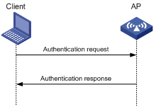
Open system authentication
Open system authentication is the default and simplest authentication algorithm. Any client that requests authentication by using this algorithm can pass the authentication.
Open system authentication uses the following process:
1. The client sends an authentication request to the AP.
2. The AP sends an authentication response to the client after the client passes the authentication.
Figure 1 Open system authentication process
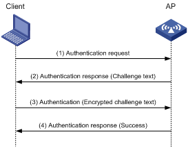
Shared key authentication
Shared key authentication uses a WEP key for the AP and client to complete authentication.
Shared key authentication uses the following process:
1. The client sends an authentication request to the AP.
2. The AP randomly generates a challenge text and sends it to the client.
3. The client uses the WEP key to encrypt the challenge text and sends it to the AP.
4. The AP uses the WEP key to decrypt the challenge text and compares the decrypted challenge text with the original challenge text. If they are identical, the client passes the authentication. If they are not, the authentication fails.
Figure 2 Shared key authentication process
RSNA mechanism
|
|
IMPORTANT: RSNA requires open system authentication for link layer authentication. |
The RSNA mechanism includes WPA and RSN security modes. RSNA provides the following features:
· 802.1X and PSK authentication and key management (AKM) for authenticating user integrity and dynamically generating and updating keys.
¡ 802.1X—802.1X performs user authentication and generates the pairwise master key (PMK) during authentication. The client and AP use the PMK to generate the pairwise transient key (PTK).
¡ Private PSK—The MAC address of the client is used as the PSK to generate the PMK. The client and AP use the PMK to generate the PTK.
¡ PSK—The PSK is used to generate the PMK. The client and AP use the PMK to generate the PTK.
· Temporal key integrity Protocol (TKIP) and Counter Mode CBC-MAC Protocol (CCMP) mechanisms for encrypting data.
Authentication
802.1X authentication is more secure than PSK authentication. For more information about 802.1X authentication, see "Configuring WLAN user access authentication."
PSK authentication requires the same PSK to be configured for both an AP and a client. PSK integrity is verified during the four-way handshake. If PTK negotiation succeeds, the client passes the authentication.
Key management
Key management defines how to generate and update the PTK and group temporary key (GTK). The PTK is used in unicast and the GTK is used in multicast and broadcast.
PTK and GTK
· PTK structure
![]()
¡ EAPOL-Key Confirmation Key (KCK) is used to verify the integrity of an EAPOL-Key frame.
¡ EAPOL-Key Encryption Key (KEK) is used to encrypt the key data in the EAPOL-Key frame.
¡ Temporal Key (TK) is used to encrypt unicast packets.
· The GTK includes the TK and other fields. The TK is used to encrypt multicast and broadcast packets.
EAPOL-Key packet
The IEEE 802.11i protocol uses EAPOL-Key packets during key negotiation.
Figure 3 EAPOL-Key structure
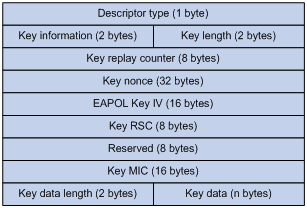
Table 1 EAPOL-Key field description
|
Field |
Description |
|
Descriptor type |
Specifies the network type: · WPA network. · RSN network. |
|
Key information |
For more information about this field, see Table 2. |
|
Key length |
Length of the key. |
|
Key replay counter |
Records the total number of GTK updates to prevent replay attacks. The AP sets this field to 0 at the beginning of the negotiation and increments the value on each successive EAPOL-Key frame. The client records this field from the last valid EAPOL-Key frame that it received if this field is greater than the field recorded previously. EAPOL-Key frame retransmission is required in the following situations: · The field received by the client is smaller than or equal to the field recorded by the client. · The field received by the AP is not equal to the field recorded on the AP. If the retransmission attempts exceed the maximum number, the AP disconnects the client. |
|
Key nonce |
Random value used to generate the PTK. |
|
EAPOL Key IV |
Encrypts the TKIP. This field is valid only when the encryption type is not CCMP. |
|
Key RSC |
Records the total number of multicast packets or broadcast packets to prevent replay attacks. The AP increments the value of this field on transmission of each multicast or broadcast packet. |
|
Reserved |
Reserved field. |
|
Key MIC |
Message integrity check. |
|
Key data length |
Length of the key data. |
|
Key data |
Data to be transmitted, such as the GTK and pairwise master key identifier (PMKID). |
Figure 4 Key information structure
![]()
Table 2 Key information description
|
Field |
Description |
|
Key Descriptor Version |
3-bit key version: · 1—Non-CCMP key. · 2—CCMP key. |
|
Key Type |
1-bit key type: · 0—Multicast negotiation key. · 1—Unicast negotiation key. |
|
Reserved |
2-bit field reserved. The sender sets this field to 0, and the receiver ignores this field. |
|
Install |
1-bit key installation field. If the Key Type field is 1, this field is 0 or 1. · 0—The AP does not request the client to install the TK. · 1—The AP requests the client to install the TK. If the Key type field is 0, the sender sets this field to 0, and the receiver ignores this field. |
|
Key Ack |
1-bit key acknowledgment field. The value 1 indicates that the AP requests an acknowledgement from the client. |
|
Key MIC |
Message integrity check. If this field is 1, the generated MIC must be included in the Key MIC field of the EAPOL-key frame. |
|
Secure |
1-bit key status. The value 1 indicates that the key has been generated. |
|
Error |
1-bit MIC check status. The value 1 indicates that a MIC failure has occurred. The client sets this field to 1 when the Request field is 1. |
|
Request |
1-bit request used by the client to request the AP to initiate the four-way handshake or multi-cast handshake in a MIC failure report. |
|
Encrypted Key Data |
1-bit key data encryption status. The value 1 indicates that the key data is encrypted. |
|
Reserved |
3-bit reserved field. The sender sets this field to 0, and the receiver ignores this field. |
WPA key negotiation
WPA uses EAPOL-Key packets in the four-way handshake to negotiate the PTK, and in the two-way handshake to negotiate the GTK.
Figure 5 WPA key negotiation process
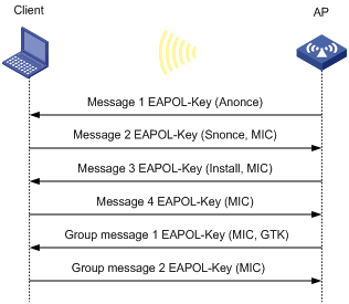
WPA key negotiation uses the following process:
1. The AP sends the client EAPOL-Key message 1 that contains a random value ANonce.
2. The client performs the following operations:
a. Uses the random value SNonce, ANonce, and PMK to generate a PTK by using the key derivation function (KDF).
b. Uses the KCK in the PTK to generate the MIC.
c. Returns EAPOL-Key message 2 that contains the SNonce and MIC.
3. The AP performs the following operations:
a. Uses the SNonce, ANonce, and PMK to generate a PTK by using the KDF.
b. Uses the KCK in the PTK to generate the MIC.
c. Compares the received MIC with the local MIC.
d. Returns EAPOL-Key message 3 that contains the PTK installation request tag and MIC if the two MICs are the same.
4. The client performs the following operations:
a. Compares the received MIC with the local MIC.
b. Installs the PTK and returns EAPOL-Key message 4 that contains the MIC if the two MICs are the same.
5. The AP performs the following operations:
a. Compares the received MIC with the local MIC.
b. Installs the PTK and generates a GTK with the GMK and MAC address of the AP by using the KDF if the two MICs are the same.
c. Returns EAPOL-Key group message 1 that contains the GTK and MIC.
6. The client performs the following operations:
a. Installs the GTK if the two MICs are the same.
b. Returns EAPOL-Key group message 2 that contains the MIC.
7. The AP performs the following operations:
a. Compares the received MIC with the local MIC.
b. Installs the GTK if the MICs are the same.
RSN key negotiation
RSN uses EAPOL-Key packets in the four-way handshake to negotiate the PTK and the GTK.
Figure 6 RSN key negotiation process
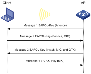
RSN key negotiation uses the following process:
1. The AP sends the client EAPOL-Key message 1 that contains a random value ANonce.
2. The client performs the following operations:
a. Uses the random value SNonce, ANonce, and PMK to generate a PTK by using the KDF.
b. Uses the KCK in the PTK to generate the MIC.
c. Returns EAPOL-Key message 2 that contains the SNonce and MIC.
3. The AP performs the following operations:
a. Uses the SNonce, ANonce, and PMK to generate a PTK by using the KDF.
b. Uses the KCK in the PTK to generate the MIC.
c. Compares the received MIC with the local MIC.
d. Generates a GTK with the random GMK and MAC address of the AP by using the KDF if the two MICs are the same.
e. Returns EAPOL-Key message 3 that contains the key installation request tag, MIC, and GTK.
4. The client performs the following operations:
a. Compares the received MIC with the local MIC.
b. Installs the PTK and GTK if the two MICs are the same.
c. Returns EAPOL-Key message 4 that contains the MIC.
5. The AP performs the following operations:
a. Compares the received MIC with the local MIC.
b. Installs the PTK and GTK if the two MICs are the same.
Key updates
Key updates enhance WLAN security. Key updates include PTK updates and GTK updates.
· PTK updates—Updates for the unicast keys using the four-way handshake negotiation.
· GTK updates—Updates for the multicast keys using the two-way handshake negotiation.
Cipher suites
TKIP
TKIP and WEP both use the RC4 algorithm. You can change the cipher suite from WEP to TKIP by updating the software without changing the hardware. TKIP has the following advantages over WEP:
· TKIP provides longer initialization vectors (IVs) to enhance encryption security. Compared with WEP encryption, TKIP encryption uses the 128-bit RC4 encryption algorithm, and increases the length of IVs from 24 bits to 48 bits.
· TKIP allows for dynamic key negotiation to avoid static key configuration. TKIP dynamic keys cannot be easily deciphered.
· TKIP offers MIC and countermeasures. If a packet has been tampered with, it will fail the MIC. If two packets fail the MIC in a period, the AP automatically takes countermeasures by stopping providing services in a period to prevent attacks.
CCMP
CCMP is based on the Counter-Mode/CBC-MAC (CCM) of the Advanced Encryption Standard (AES) encryption algorithm.
CCMP contains a dynamic key negotiation and management method. Each client can dynamically negotiate a key suite, which can be updated periodically to further enhance the security of the CCMP cipher suite. During the encryption process, CCMP uses a 48-bit packet number (PN) to make sure each encrypted packet uses a different PN. This improves WLAN security.
Management frame protection
The management frame protection service protects a set of robust management frames, such as de-authentication, disassociation, and some robust action frames. Management frame protection uses the PTK to encrypt unicast management frames and provides secrecy, integrity, and replay protection. It uses the Broadcast Integrity Protocol (BIP) to provide integrity and replay protection for broadcast and multicast management frames.
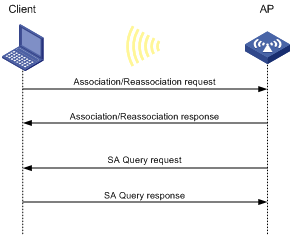
The security association (SA) query mechanism is used to enhance security if the AP and client negotiate to use management frame protection. SA queries include active SA queries and passive SA queries.
· Active SA query
As shown in Figure 7, active SA query uses the following process:
a. The client sends an association or reassociation request to the AP.
b. Upon receiving the request, the AP sends a response to inform the client that the request is denied and the client can associate at a later time. The response contains the association comeback time.
c. The AP sends an SA query request to verify the status of the client:
- If the AP receives an SA query response within the timeout time, it determines that the client is online.
- If the AP does not receive an SA query response within the timeout time, it sends another SA query request. If the AP receives an SA query response within the retransmission time, it determines that the client is online. The AP does not respond to any association or reassociation requests from the client until the association comeback time times out.
- If the AP does not receive an SA query response within the retransmission time, it determines that the client is offline and allows the client to reassociate.
Figure 7 Active SA query process
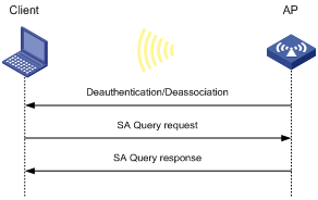
· Passive SA query
As shown in Figure 8, passive SA query uses the following process:
a. The client triggers the SA query process upon receiving an unencrypted disassociation or deauthentication frame.
b. The client sends an SA query request to the AP.
c. The AP sends an SA query response to the client:
- If the client receives the response, the client determines that the AP is online and does not process the disassociation or deauthentication frame.
- If the client does not receive a response, the client determines that the AP is offline and disassociates with the AP.
Figure 8 Passive SA query process
Dynamic WEP mechanism
|
|
IMPORTANT: The dynamic WEP mechanism uses open system authentication for link layer authentication. |
IEEE 802.11 provides the dynamic WEP mechanism to ensure that each user uses a private WEP key. For unicast communications, the mechanism uses the WEP key negotiated by the client and server during 802.1X authentication. For multicast and broadcast communications, the mechanism uses the configured WEP key. If you do not configure a WEP key, the AP randomly generates a WEP key for broadcast and multicast communications.
After the client passes 802.1X authentication, the AP sends the client an RC4-EAPOL packet that contains the unicast WEP key ID, and the multicast and broadcast WEP key and key ID. The unicast WEP key ID is 4.
Protocols and standards
· IEEE Standard for Information technology—Telecommunications and information exchange between systems—Local and metropolitan area networks—Specific requirements—2004
· WI-FI Protected Access—Enhanced Security Implementation Based On IEEE P802.11i Standard-Aug 2004
· Information technology—Telecommunications and information exchange between systems—Local and metropolitan area networks—Specific requirements—802.11, 1999
· IEEE Standard for Local and metropolitan area networks "Port-Based Network Access Control" 802.1X™-2004
· 802.11i IEEE Standard for Information technology—Telecommunications and information exchange between systems—Local and metropolitan area networks—Specific requirements
· 802.11w IEEE Standard for Information technology—Telecommunications and information exchange between systems—Local and metropolitan area networks—Specific requirements
WLAN security configuration task lists
|
IMPORTANT: · RSNA requires open system authentication for link layer authentication. · The dynamic WEP mechanism requires 802.1X authentication for user access authentication. · The AKM mode, security IE, and cipher suite must be configured for RSNA networks. · Management frame protection takes effect only for a network that uses the RSNA mechanism and is configured with the CCMP cipher suite and RSN security information element. |
To configure the pre-RSNA mechanism, perform the following tasks:
|
Tasks at a glance |
|
(Required.) Setting the cipher suite |
|
(Required.) Setting the WEP key |
|
(Optional.) Enabling SNMP notifications for WLAN security |
To configure the RSNA mechanism, perform the following tasks:
|
Tasks at a glance |
|
(Required.) Configuring the AKM mode |
|
(Required.) Setting the security information element |
|
(Required.) Setting the cipher suite |
|
(Optional.) Setting the PSK |
|
(Optional.) Setting the KDF |
|
(Optional.) Configuring GTK update |
|
(Optional.) Setting the PTK lifetime |
|
(Optional.) Setting the TKIP MIC failure hold time |
|
(Optional.) Setting the WEP key |
|
(Optional.) Configuring management frame protection |
|
(Optional.) Enabling SNMP notifications for WLAN security |
To configure the dynamic WEP mechanism, perform the following tasks:
|
Tasks at a glance |
|
(Optional.) Setting the cipher suite |
|
(Optional.) Setting the WEP key |
|
(Required.) Enabling the dynamic WEP mechanism |
|
(Optional.) Enabling SNMP notifications for WLAN security |
|
|
NOTE: · If a WEP key is configured, the dynamic WEP mechanism uses the configured WEP key as the multicast and broadcast WEP key. The negotiated unicast WEP has an ID of 4 and uses the cipher suite length setting. · If no WEP key is configured, the length for both dynamic WEP keys is 104 bits. The negotiated unicast WEP key has an ID of 4. The generated multicast and broadcast WEP key has an ID of 1. |
Configuring the AKM mode
Each of the following AKM modes must be used with a specific authentication mode:
· 802.1X AKM—802.1X authentication mode.
· Private PSK AKM—MAC authentication mode.
· PSK AKM—MAC or bypass authentication mode.
· WiFi alliance anonymous 802.1X AKM—802.1X authentication mode.
To configure the AKM mode:
|
Step |
Command |
Remarks |
|
1. Enter system view. |
system-view |
N/A |
|
1. Enter WLAN service template view. |
wlan service-template service-template-name |
N/A |
|
2. Configure the AKM mode. |
akm mode { dot1x | private-psk | psk | anonymous-dot1x } |
By default, no AKM mode is configured. |
Setting the security information element
|
Step |
Command |
Remarks |
|
1. Enter system view. |
system-view |
N/A |
|
2. Enter WLAN service template view. |
wlan service-template service-template-name |
N/A |
|
3. Set the security IE. |
security-ie { osen | rsn | wpa } |
By default, no security IE is set. |
Setting the cipher suite
Cipher suites include:
· WEP (WEP40, WEP104, or WEP128).
· CCMP.
· TKIP.
To set the cipher suite:
|
Step |
Command |
Remarks |
|
1. Enter system view. |
system-view |
N/A |
|
2. Enter WLAN service template view. |
wlan service-template service-template-name |
N/A |
|
3. Set the cipher suite. |
cipher-suite { ccmp | tkip | wep40 | wep104 | wep128 } |
By default, no cipher suite is set. You cannot set both WEP 128 and CCMP or both WEP 128 and TKIP. |
Setting the PSK
The PSK must be set if the AKM mode is PSK. If you configure the PSK when the AKM mode is 802.1X, the WLAN service template can be enabled but the PSK configuration does not take effect.
To set the PSK:
|
Step |
Command |
Remarks |
|
1. Enter system view. |
system-view |
N/A |
|
2. Enter WLAN service template view. |
wlan service-template service-template-name |
N/A |
|
3. Set the PSK. |
preshared-key { pass-phrase | raw-key } { cipher | simple } key |
By default, no PSK is set. |
Setting the KDF
KDFs are used by RSNA networks to generate PTKs and GTKs. KDFs include HMAC-SHA1 and HMAC-SHA256 algorithms. The HMAC-SHA256 algorithm is more secure than the HMAC-SHA1 algorithm.
To set the KDF:
|
Step |
Command |
Remarks |
|
1. Enter system view. |
system-view |
N/A |
|
2. Enter WLAN service template view. |
wlan service-template service-template-name |
N/A |
|
3. Set the KDF. |
key-derivation { sha1 | sha256 | sha1-and-sha256 } |
By default, the HMAC-SHA1 algorithm is set. |
Configuring GTK update
The system generates the GTK during key negotiation if the AKM, security IE, and cipher suite are configured. This feature updates the GTK to enhance key security based on the following updating modes:
· Time-based—The GTK is updated at the specified interval.
· Packet-based—The GTK is updated after the specified number of packets is sent.
· Offline-triggered—The GTK is updated when a client in the basic service set (BSS) goes offline.
To configure GTK update:
|
Step |
Command |
Remarks |
|
1. Enter system view. |
system-view |
N/A |
|
2. Enter WLAN service template view. |
wlan service-template service-template-name |
N/A |
|
3. Enable GTK update. |
gtk-rekey enable |
By default, GTK update is enabled. |
|
4. (Optional.) Configure a GTK update method. |
gtk-rekey method { packet-based [ packet ] | time-based [ time ] } |
By default, the GTK is updated at an interval of 85400 seconds. The default packet quantity is 10000000 for packet-based GTK update. |
|
5. (Optional.) Enable the offline-triggered GTK update. |
gtk-rekey client-offline enable |
By default, offline-triggered GTK update is disabled. |
Setting the PTK lifetime
About the PTK lifetime
The system generates the PTK during key negotiation when the AKM, security IE, and cipher suite are configured. This feature updates the PTK after the PTK lifetime expires.
Procedure
|
Step |
Command |
Remarks |
|
1. Enter system view. |
system-view |
N/A |
|
2. Enter WLAN service template view. |
wlan service-template service-template-name |
N/A |
|
3. Enable PTK rekey. |
ptk-rekey enable |
By default, PTK rekey is enabled. |
|
4. Set the PTK lifetime. |
ptk-lifetime time |
By default, the PTK lifetime is 43200 seconds. |
Setting the TKIP MIC failure hold time
After configuring the TKIP, you can configure the TKIP MIC failure hold time. If the AP detects two MIC failures within the MIC failure hold time, it disassociates all clients for 60 seconds.
To set the TKIP MIC failure hold time:
|
Step |
Command |
Remarks |
|
1. Enter system view. |
system-view |
N/A |
|
2. Enter WLAN service template view. |
wlan service-template service-template-name |
N/A |
|
3. Set the TKIP MIC failure hold time. |
tkip-cm-time time |
By default, the TKIP MIC failure hold time is 0. The AP does not take any countermeasures. |
Setting the WEP key
The WEP key can be used to encrypt all packets for pre-RSNA networks and encrypt multicast packets for RSNA networks. If the WEP key is not set, a pre-RSNA network does not encrypt packets and an RSNA network uses the negotiated GTK to encrypt multicast packets.
To set the WEP key:
|
Step |
Command |
Remarks |
|
1. Enter system view. |
system-view |
N/A |
|
2. Enter WLAN service template view. |
wlan service-template service-template-name |
N/A |
|
3. Set the WEP key. |
wep key key-id { wep40 | wep104 | wep128 } { pass-phrase | raw-key } { cipher | simple } key |
By default, no WEP key is set. |
|
4. (Optional.) Apply the WEP key. |
wep key-id { 1 | 2 | 3 | 4 } |
By default, WEP key 1 is applied. Do not apply WEP key 4 if the dynamic WEP mechanism is enabled. |
Configuring management frame protection
Management frame protection takes effect only for a network that uses the RSNA mechanism and is configured with the CCMP cipher suite and RSN security information element.
If management frame protection is disabled, network access is available for all clients, but management frame protection is not performed. If management frame protection is enabled, the network access and management frame protection availability varies by management frame protection mode.
· Optional mode—Network access is available for all clients, but management frame protection is performed only for clients that support management frame protection.
· Mandatory mode—Network access and management frame protection are available only for clients that support management frame protection.
To configure management frame protection:
|
Step |
Command |
Remarks |
|
1. Enter system view. |
system-view |
N/A |
|
2. Enter WLAN service template view. |
wlan service-template service-template-name |
N/A |
|
3. Enable management frame protection. |
pmf { optional | mandatory } |
By default, management frame protection is disabled. |
|
4. Set the interval for sending SA query requests. |
pmf saquery retrytimeout timeout |
By default, the interval for sending SA query requests is 200 milliseconds. |
|
5. Set the maximum transmission attempts for SA query requests. |
pmf saquery retrycount count |
By default, the maximum retransmission attempt number is 4 for SA query requests. |
|
6. Set the association comeback time. |
pmf association-comeback time |
By default, the association comeback time is 1 second. |
Enabling the dynamic WEP mechanism
The dynamic WEP mechanism must be used with the 802.1X authentication mode.
To enable the dynamic WEP mechanism:
|
Step |
Command |
Remarks |
|
1. Enter system view. |
system-view |
N/A |
|
2. Enter WLAN service template view. |
wlan service-template service-template-name |
N/A |
|
3. Enable the dynamic WEP mechanism. |
wep mode dynamic |
By default, the dynamic WEP mechanism is disabled. |
Enabling SNMP notifications for WLAN security
To report critical WLAN security events to an NMS, enable SNMP notifications for WLAN security. For WLAN security event notifications to be sent correctly, you must also configure SNMP as described in Network Management and Monitoring Configuration Guide.
To enable SNMP notifications for WLAN security:
|
Step |
Command |
Remarks |
|
1. Enter system view. |
system-view |
N/A |
|
2. Enable SNMP notifications for WLAN security. |
snmp-agent trap enable wlan usersec |
By default, SNMP notifications are disabled for WLAN security. |
Displaying and maintaining WLAN security
Execute display commands in any view.
|
Task |
Command |
|
Display WLAN service template information. |
display wlan service-template [ service-template-name ] [ verbose ] For more information about this command, see "WLAN access commands." |
|
Display client information. |
display wlan client [ ap ap-name [ radio radio-id ] | mac-address mac-address | service-template service-template-name ] [ verbose ] For more information about this command, see "WLAN access commands." |
WLAN security configuration examples
Shared key authentication configuration example
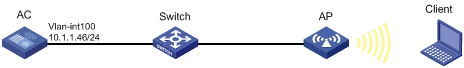
Network requirements
As shown in Figure 9, the switch functions as a DHCP server to assign IP addresses to the AP and client. Configure shared key authentication to enable the client to access the network by using the WEP key 12345.
Configuration procedure
# Create a WLAN service template named service1.
<AC> system-view
[AC] wlan service-template service1
# Specify the SSID service for the service template.
[AC-wlan-st-service1] ssid service
# Specify the cipher suite wep40 and key 12345 for the service template service1, and apply the key with the ID 2.
[AC-wlan-st-service1] cipher-suite wep40
[AC-wlan-st-service1] wep key 2 wep40 pass-phrase simple 12345
[AC-wlan-st-service1] wep key-id 2
# Enable the service template service1.
[AC-wlan-st-service1] service-template enable
[AC-wlan-st-service1] quit
# Create an AP named ap1 and specify the model and serial ID.
[AC] wlan ap ap1 model WA4320i-ACN
[AC-wlan-ap-ap1] serial-id 219801A0CNC138011454
# Bind the service template service1 to radio 1 of the AP, and enable radio 1.
[AC-wlan-ap-ap1] radio 1
[AC-wlan-ap-ap1-radio-1] service-template service1
[AC-wlan-ap-ap1-radio-1] radio enable
[AC-wlan-ap-ap1-radio-1] return
Verifying the configuration
# Use the display wlan service-template command to verify that the WLAN service template has been configured correctly.
<AC> display wlan service-template service1 verbose
Service template name : service1
Description : Not configured
SSID : service
SSID-hide : Disabled
User-isolation : Disabled
Service template status : Enabled
Maximum clients per BSS : 64
Frame format : Dot3
Seamless roam status : Disabled
Seamless roam RSSI threshold : 50
Seamless roam RSSI gap : 20
VLAN ID : 1
AKM mode : Not configured
Security IE : Not configured
Cipher suite : WEP40
WEP key ID : 2
TKIP countermeasure time : 0
PTK lifetime : 43200 sec
GTK rekey : Enabled
GTK rekey method : Time-based
GTK rekey time : 86400 sec
GTK rekey client-offline : Enabled
User authentication mode : Bypass
Intrusion protection : Disabled
Intrusion protection mode : Temporary-block
Temporary block time : 180 sec
Temporary service stop time : 20 sec
Fail VLAN ID : Not configured
802.1X handshake : Disabled
802.1X handshake secure : Disabled
802.1X domain : Not configured
MAC-auth domain : Not configured
Max 802.1X users per BSS : 4096
Max MAC-auth users per BSS : 4096
802.1X re-authenticate : Disabled
Authorization fail mode : Online
Accounting fail mode : Online
Authorization : Permitted
Key derivation : N/A
PMF status : Disabled
Hotspot policy number : Not configured
Forwarding policy status : Disabled
Forwarding policy name : Not configured
Forwarder : AC
FT status : Disabled
QoS trust : Port
QoS priority : 0
PSK authentication and bypass authentication configuration example
Network requirements
As shown in Figure 10, the switch functions as a DHCP server to assign IP addresses to the AP and client.
· Configure open system authentication and bypass authentication.
· Configure the client to use the preshared key 12345678 to access the network.
Configuration procedure
1. Create a WLAN service template named service1.
<AC> system-view
[AC] wlan service-template service1
2. Specify the SSID service for the service template.
[AC-wlan-st-service1] ssid service
3. Configure WLAN security for the service template service1:
# Configure PSK as the AKM mode and specify the plaintext key 12345678.
[AC-wlan-st-service1] akm mode psk
[AC-wlan-st-service1] preshared-key pass-phrase simple 12345678
# Configure CCMP as the cipher suite and WPA as the security IE.
[AC-wlan-st-service1] cipher-suite ccmp
[AC-wlan-st-service1] security-ie wpa
4. Enable the service template service1.
[AC-wlan-st-service1] service-template enable
[AC-wlan-st-service1] quit
5. Create an AP named ap1 and specify the model and serial ID.
[AC] wlan ap ap1 model WA4320i-ACN
[AC-wlan-ap-ap1] serial-id 219801A0CNC138011454
6. Bind the service template service1 to radio 1 of the AP, and enable radio 1.
[AC-wlan-ap-ap1] radio 1
[AC-wlan-ap-ap1-radio-1] service-template service1
[AC-wlan-ap-ap1-radio-1] radio enable
[AC-wlan-ap-ap1-radio-1] return
Verifying the configuration
# Use the display wlan service-template command to verify that the WLAN service template has been configured correctly.
<AC> display wlan service-template service1 verbose
Service template name : service1
Description : Not configured
SSID : service
SSID-hide : Disabled
User-isolation : Disabled
Service template status : Enabled
Maximum clients per BSS : 64
Frame format : Dot3
Seamless roam status : Disabled
Seamless roam RSSI threshold : 50
Seamless roam RSSI gap : 20
VLAN ID : 1
AKM mode : PSK
Security IE : WPA
Cipher suite : CCMP
TKIP countermeasure time : 0
PTK lifetime : 43200 sec
GTK rekey : Enabled
GTK rekey method : Time-based
GTK rekey time : 86400 sec
GTK rekey client-offline : Enabled
User authentication mode : Bypass
Intrusion protection : Disabled
Intrusion protection mode : Temporary-block
Temporary block time : 180 sec
Temporary service stop time : 20 sec
Fail VLAN ID : Not configured
802.1X handshake : Disabled
802.1X handshake secure : Disabled
802.1X domain : Not configured
MAC-auth domain : Not configured
Max 802.1X users per BSS : 4096
Max MAC-auth users per BSS : 4096
802.1X re-authenticate : Disabled
Authorization fail mode : Online
Accounting fail mode : Online
Authorization : Permitted
Key derivation : N/A
PMF status : Disabled
Hotspot policy number : Not configured
Forwarding policy status : Disabled
Forwarding policy name : Not configured
Forwarder : AC
FT status : Disabled
QoS trust : Port
QoS priority : 0
PSK authentication and MAC authentication configuration example
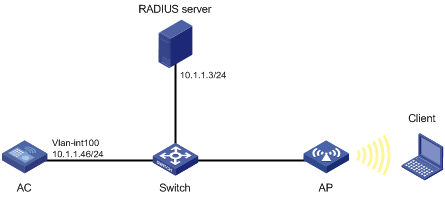
Network requirements
As shown in Figure 11, the switch functions as a DHCP server to assign IP addresses to the AP and client.
· Configure open system authentication and MAC authentication so that the client can access the network by using the login username abc and password 123.
· Configure the client to use the preshared key 12345678 to access the network.

Configuration procedure
1. Configure the username abc and the password 123 on the RADIUS server and make sure the RADIUS server and AC can reach each other. (Details not shown.)
2. Create a WLAN service template named service1 with an SSID of service.
<AC> system-view
[AC] wlan service-template service1
[AC-wlan-st-service1] ssid service
3. Configure WLAN security for the service template service1:
# Configure PSK as the AKM mode and specify the plaintext key 12345678.
[AC-wlan-st-service1] akm mode psk
[AC-wlan-st-service1] preshared-key pass-phrase simple 12345678
# Configure CCMP as the cipher suite and WPA as the security IE.
[AC-wlan-st-service1] cipher-suite ccmp
[AC-wlan-st-service1] security-ie wpa
# Configure MAC authentication.
[AC-wlan-st-service1] client-security authentication-mode mac
4. Enable the service template service1.
[AC-wlan-st-service1] service-template enable
[AC-wlan-st-service1] quit
5. Configure a RADIUS scheme:
# Create a RADIUS scheme named radius1 and enter its view.
[AC] radius scheme radius1
# Specify the primary authentication server and accounting server.
[AC-radius-radius1] primary authentication 10.1.1.3 1812
[AC-radius-radius1] primary accounting 10.1.1.3 1813
# Set the shared keys for authentication and accounting to 12345678 in plaintext.
[AC-radius-radius1] key authentication simple 12345678
[AC-radius-radius1] key accounting simple 12345678
# Set the format for the usernames sent to the RADIUS server based on the RADIUS server configuration:
¡ Exclude domain names from the usernames sent to the RADIUS server.
[Device-radius-rs1] user-name-format without-domain
[Device-radius-rs1] quit
¡ Include domain names in the usernames sent to the RADIUS server.
[Device-radius-rs1] user-name-format with-domain
[Device-radius-rs1] quit
6. Create an ISP domain named dom1 and configure a RADIUS scheme for the ISP domain.
[AC] domain dom1
[AC-isp-dom1] authentication lan-access radius-scheme radius1
[AC-isp-dom1] authorization lan-access radius-scheme radius1
[AC-isp-dom1] accounting lan-access radius-scheme radius1
[AC-isp-dom1] quit
7. Configure the ISP domain dom1, username abc, and password 123 for the user.
[AC] mac-authentication mac domain dom1
[AC] mac-authentication user-name-format fixed account abc password simple 123
8. Create an AP named ap1 and specify the model and serial ID.
[AC] wlan ap ap1 model WA4320i-ACN
[AC-wlan-ap-ap1] serial-id 219801A0CNC138011454
9. Bind the service template service1 to radio 1 of the AP, and enable radio 1.
[AC-wlan-ap-ap1] radio 1
[AC-wlan-ap-ap1-radio-1] service-template service1
[AC-wlan-ap-ap1-radio-1] radio enable
[AC-wlan-ap-ap1-radio-1] return
|
|
NOTE: For more information about the AAA and RADIUS commands in this section, see Security Command Reference. |
Verifying the configuration
# Use the display wlan service-template command to verify that the WLAN service template has been configured correctly.
<AC> display wlan service-template service1 verbose
Service template name : service1
Description : Not configured
SSID : service
SSID-hide : Disabled
User-isolation : Disabled
Service template status : Enabled
Maximum clients per BSS : 64
Frame format : Dot3
Seamless roam status : Disabled
Seamless roam RSSI threshold : 50
Seamless roam RSSI gap : 20
VLAN ID : 1
AKM mode : PSK
Security IE : WPA
Cipher suite : CCMP
TKIP countermeasure time : 0
PTK lifetime : 43200 sec
GTK rekey : Enabled
GTK rekey method : Time-based
GTK rekey time : 86400 sec
GTK rekey client-offline : Enabled
User authentication mode : MAC
Intrusion protection : Disabled
Intrusion protection mode : Temporary-block
Temporary block time : 180 sec
Temporary service stop time : 20 sec
Fail VLAN ID : Not configured
802.1X handshake : Disabled
802.1X handshake secure : Disabled
802.1X domain : Not configured
MAC-auth domain : Not configured
Max 802.1X users per BSS : 4096
Max MAC-auth users per BSS : 4096
802.1X re-authenticate : Disabled
Authorization fail mode : Online
Accounting fail mode : Online
Authorization : Permitted
Key derivation : N/A
PMF status : Disabled
Hotspot policy number : Not configured
Forwarding policy status : Disabled
Forwarding policy name : Not configured
Forwarder : AC
FT status : Disabled
QoS trust : Port
QoS priority : 0
802.1X AKM configuration example
Network requirements
As shown in Figure 12, the switch functions as a DHCP server to assign IP addresses to the AP and client.
· Configure open system authentication and 802.1X authentication so that the client can access the network by using the login username abcdef and password 123456.
· Configure 802.1X as the AKM mode.

Configuration procedure
1. Configure the username abcdef and the password 123456 on the RADIUS server and make sure the RADIUS server and AC can reach each other. (Details not shown.)
2. Configure the 802.1X client. (Details not shown.)
3. Create a WLAN service template named service1.
<AC> system-view
[AC] wlan service-template service1
4. Specify the SSID service for the service template.
[AC-wlan-st-service1] ssid service
5. Configure WLAN security for the service template service1:
# Configure 802.1X as the AKM mode.
[AC-wlan-st-service1] akm mode dot1x
# Configure CCMP as the cipher suite and WPA as the security IE.
[AC-wlan-st-service1] cipher-suite ccmp
[AC-wlan-st-service1] security-ie wpa
# Configure the 802.1X authentication mode.
[AC-wlan-st-service1] client-security authentication-mode dot1x
6. Enable the service template service1.
[AC-wlan-st-service1] service-template enable
[AC-wlan-st-service1] quit
7. Configure a RADIUS scheme:
# Create a RADIUS scheme named radius1 and enter its view.
[AC] radius scheme radius1
# Specify the primary authentication server and accounting server.
[AC-radius-radius1] primary authentication 10.1.1.3 1812
[AC-radius-radius1] primary accounting 10.1.1.3 1813
# Set the shared keys for authentication and accounting to 12345 in plaintext.
[AC-radius-radius1] key authentication simple 12345
[AC-radius-radius1] key accounting simple 12345
# Set the format for the usernames sent to the RADIUS server based on the RADIUS server configuration:
¡ Exclude domain names from the usernames sent to the RADIUS server.
[Device-radius-rs1] user-name-format without-domain
[Device-radius-rs1] quit
¡ Include domain names in the usernames sent to the RADIUS server.
[Device-radius-rs1] user-name-format with-domain
[Device-radius-rs1] quit
8. Create an ISP domain named dom1 and configure a RADIUS scheme for the ISP domain.
[AC] domain dom1
[AC-isp-dom1] authentication lan-access radius-scheme radius1
[AC-isp-dom1] authorization lan-access radius-scheme radius1
[AC-isp-dom1] accounting lan-access radius-scheme radius1
[AC-isp-dom1] quit
9. Configure dom1 as the default ISP domain.
[AC] domain default enable dom1
10. Create an AP named ap1 and specify the model and serial ID.
[AC] wlan ap ap1 model WA4320i-ACN
[AC-wlan-ap-ap1] serial-id 219801A0CNC138011454
11. Bind the service template service1 to radio 1 of the AP, and enable radio 1.
[AC-wlan-ap-ap1] radio 1
[AC-wlan-ap-ap1-radio-1] service-template service1
[AC-wlan-ap-ap1-radio-1] radio enable
[AC-wlan-ap-ap1-radio-1] return
|
|
NOTE: For more information about the AAA and RADIUS commands in this section, see Security Command Reference. |
Verifying the configuration
# Use the display wlan service-template command to verify that the WLAN service template has been configured correctly.
<AC> display wlan service-template service1 verbose
Service template name : service1
Description : Not configured
SSID : service
SSID-hide : Disabled
User-isolation : Disabled
Service template status : Enabled
Maximum clients per BSS : 64
Frame format : Dot3
Seamless roam status : Disabled
Seamless roam RSSI threshold : 50
Seamless roam RSSI gap : 20
VLAN ID : 1
AKM mode : dot1x
Security IE : WPA
Cipher suite : CCMP
TKIP countermeasure time : 0
PTK lifetime : 43200 sec
GTK rekey : Enabled
GTK rekey method : Time-based
GTK rekey time : 86400 sec
GTK rekey client-offline : Enabled
User authentication mode : 802.1X
Intrusion protection : Disabled
Intrusion protection mode : Temporary-block
Temporary block time : 180 sec
Temporary service stop time : 20 sec
Fail VLAN ID : Not configured
802.1X handshake : Disabled
802.1X handshake secure : Disabled
802.1X domain : Not configured
MAC-auth domain : Not configured
Max 802.1X users per BSS : 4096
Max MAC-auth users per BSS : 4096
802.1X re-authenticate : Disabled
Authorization fail mode : Online
Accounting fail mode : Online
Authorization : Permitted
Key derivation : N/A
PMF status : Disabled
Hotspot policy number : Not configured
Forwarding policy status : Disabled
Forwarding policy name : Not configured
Forwarder : AC
FT status : Disabled
QoS trust : Port
QoS priority : 0
Management frame protection configuration example
Network requirements
As shown in Figure 13, the switch functions as a DHCP server to assign IP addresses to the AP and client.
· Configure the client to use the preshared key 12345678 to access the network.
· Configure the CCMP cipher suite, RSN security IE, and management frame protection.
Configuration procedure
1. Create a WLAN service template named service1.
<AC> system-view
[AC] wlan service-template service1
2. Specify the SSID service for the service template.
[AC-wlan-st-service1] ssid service
3. Configure management frame protection:
# Enable management frame protection in optional mode.
[AC-wlan-st-service1] pmf optional
# Set the KDF to sha1-and-sha256.
[AC-wlan-st-service1] key-derivation sha1-and-sha256
4. Configure the RSNA mechanism:
# Configure PSK as the AKM mode and specify the plaintext key 12345678.
[AC-wlan-st-service1] akm mode psk
[AC-wlan-st-service1] preshared-key pass-phrase simple 12345678
# Configure CCMP as the cipher suite and RSN as the security IE.
[AC-wlan-st-service1] cipher-suite ccmp
[AC-wlan-st-service1] security-ie rsn
5. Enable the service template service1.
[AC-wlan-st-service1] service-template enable
[AC-wlan-st-service1] quit
6. Create an AP named ap1 and specify the model and serial ID.
[AC] wlan ap ap1 model WA4320i-ACN
[AC-wlan-ap-ap1] serial-id 219801A0CNC138011454
7. Bind the service template service1 to radio 1 of the AP, and enable radio 1.
[AC-wlan-ap-ap1] radio 1
[AC-wlan-ap-ap1-radio-1] service-template service1
[AC-wlan-ap-ap1-radio-1] radio enable
[AC-wlan-ap-ap1-radio-1] return
Verifying the configuration
# Use the display wlan service-template command to verify that the WLAN service template has been configured correctly.
<AC> display wlan service-template service1 verbose
Service template name : service1
Description : Not configured
SSID : service
SSID-hide : Disabled
User-isolation : Disabled
Service template status : Enabled
Maximum clients per BSS : 64
Frame format : Dot3
Seamless roam status : Disabled
Seamless roam RSSI threshold : 50
Seamless roam RSSI gap : 20
VLAN ID : 1
AKM mode : PSK
Security IE : RSN
Cipher suite : CCMP
TKIP countermeasure time : 0
PTK lifetime : 43200 sec
GTK rekey : Enabled
GTK rekey method : Time-based
GTK rekey time : 86400 sec
GTK rekey client-offline : Enabled
User authentication mode : Bypass
Intrusion protection : Disabled
Intrusion protection mode : Temporary-block
Temporary block time : 180 sec
Temporary service stop time : 20 sec
Fail VLAN ID : Not configured
802.1X handshake : Disabled
802.1X handshake secure : Disabled
802.1X domain : Not configured
MAC-auth domain : Not configured
Max 802.1X users per BSS : 4096
Max MAC-auth users per BSS : 4096
802.1X re-authenticate : Disabled
Authorization fail mode : Online
Accounting fail mode : Online
Authorization : Permitted
Key derivation : SHA1-AND-SHA256
PMF status : Optional
Hotspot policy number : Not configured
Forwarding policy status : Disabled
Forwarding policy name : Not configured
Forwarder : AC
FT status : Disabled
QoS trust : Port
QoS priority : 0
# Use the display wlan client verbose command to verify the management frame protection negotiation results after a 802.11w client comes online.
<AC> display wlan client verbose
Total number of clients: 1
MAC address : 5250-0012-0411
IPv4 address : 135.3.2.1
IPv6 address : N/A
Username : 11w
AID : 1
AP ID : 1
AP name : ap1
Radio ID : 1
SSID : service
BSSID : 1111-2222-3333
VLAN ID : 1
Sleep count : 147
Wireless mode : 802.11a
Channel bandwidth : 20MHz
SM power save : Disabled
Short GI for 20MHz : Not supported
Short GI for 40MHz : Not supported
STBC RX capability : Not supported
STBC TX capability : Not supported
LDPC RX capability : Not supported
Block Ack : TID 0 In
Support HT-MCS set : 0, 1, 2, 3, 4, 5, 6, 7,
8, 9, 10, 11, 12, 13, 14,
15
Supported rates : 1, 2, 5.5, 6, 9, 11,
12, 18, 24, 36, 48, 54 Mbps
QoS mode : WMM
Listen interval : 10
RSSI : 46
Rx/Tx rate : 39/65
Authentication method : Open system
Security mode : RSN
AKM mode : 802.1X
Cipher suite : CCMP
User authentication mode : 802.1X
Authorization ACL ID : N/A
Authorization user profile : N/A
Roam status : N/A
Key derivation : SHA1
PMF status : Enabled
Forwarding policy name : N/A
Online time : 0days 0hours 2minutes 56seconds
FT status : Inactive
Dynamic WEP mechanism configuration example
Network requirements
As shown in Figure 14, the switch functions as a DHCP server to assign IP addresses to the AP and client.
· Configure open system authentication and 802.1X authentication so that the client can access the network by using the login username abcdef and password 123456.
· Configure the dynamic WEP mechanism.
Configuration procedure
1. Configure the username abcdef and the password 123456 on the RADIUS server and make sure the RADIUS server and AC can reach each other. (Details not shown.)
2. Configure the 802.1X client. (Details not shown.)
3. Create a WLAN service template named service1.
<AC> system-view
[AC] wlan service-template service1
4. Specify the SSID service for the service template.
[AC-wlan-st-service1] ssid service
5. Enable the dynamic WEP mechanism.
[AC-wlan-st-service1] wep mode dynamic
6. Configure the 802.1X authentication mode.
[AC-wlan-st-service1] client-security authentication-mode dot1x
7. Enable the service template service1.
[AC-wlan-st-service1] service-template enable
[AC-wlan-st-service1] quit
8. Configure a RADIUS scheme:
# Create a RADIUS scheme named radius1 and enter its view.
[AC] radius scheme radius1
# Specify the primary authentication server and accounting server.
[AC-radius-radius1] primary authentication 10.1.1.3 1812
[AC-radius-radius1] primary accounting 10.1.1.3 1813
# Set the shared keys for authentication and accounting to 12345 in plaintext.
[AC-radius-radius1] key authentication simple 12345
[AC-radius-radius1] key accounting simple 12345
# Set the format for the usernames sent to the RADIUS server based on the RADIUS server configuration:
¡ Exclude domain names from the usernames sent to the RADIUS server.
[Device-radius-rs1] user-name-format without-domain
[Device-radius-rs1] quit
¡ Include domain names in the usernames sent to the RADIUS server.
[Device-radius-rs1] user-name-format with-domain
[Device-radius-rs1] quit
9. Create an ISP domain named dom1 and configure a RADIUS scheme for the ISP domain.
[AC] domain dom1
[AC-isp-dom1] authentication lan-access radius-scheme radius1
[AC-isp-dom1] authorization lan-access radius-scheme radius1
[AC-isp-dom1] accounting lan-access radius-scheme radius1
[AC-isp-dom1] quit
10. Configure dom1 as the default ISP domain.
[AC] domain default enable dom1
11. Create an AP named ap1 and specify the model and serial ID.
[AC] wlan ap ap1 model WA4320i-ACN
[AC-wlan-ap-ap1] serial-id 219801A0CNC138011454
12. Bind the service template service1 to radio 1 of the AP, and enable radio 1.
[AC-wlan-ap-ap1] radio 1
[AC-wlan-ap-ap1-radio-1] service-template service1
[AC-wlan-ap-ap1-radio-1] radio enable
[AC-wlan-ap-ap1-radio-1] return
|
|
NOTE: For more information about the AAA and RADIUS commands in this section, see Security Command Reference. |
Verifying the configuration
# Use the display wlan service-template command to verify that the WLAN service template has been configured correctly.
<AC> display wlan service-template service1 verbose
Service template name : service1
Description : Not configured
SSID : service
SSID-hide : Disabled
User-isolation : Disabled
Service template status : Enabled
Maximum clients per BSS : 64
Frame format : Dot3
Seamless roam status : Disabled
Seamless roam RSSI threshold : 50
Seamless roam RSSI gap : 20
VLAN ID : 1
AKM mode : Not configured
Security IE : Not configured
Cipher suite : WEP104
TKIP countermeasure time : 0
PTK lifetime : 43200 sec
GTK rekey : Enabled
GTK rekey method : Time-based
GTK rekey time : 86400 sec
GTK rekey client-offline : Enabled
User authentication mode : 802.1X
Intrusionprotection : Disabled
Intrusionprotection mode : Temporary-block
Temporary block time : 180 sec
Temporaryservicestop time : 20 sec
Fail VLAN ID : Not configured
802.1X handshake : Disabled
802.1X handshake secure : Disabled
802.1X domain : Not configured
MAC-auth domain : Not configured
Max 802.1X users per BSS : 4096
Max MAC-auth users per BSS : 4096
802.1X re-authenticate : Disabled
Authorization fail mode : Online
Accounting fail mode : Online
Authorization : Permitted
Key derivation : N/A
PMF status : Disabled
Hotspot policy number : Not configured
Forwarding policy status : Disabled
Forwarding policy name : Not configured
Forwarder : AC
FT status : Disabled
QoS trust : Port
QoS priority : 0
Private PSK authentication and MAC authentication configuration example
Network requirements
As shown in Figure 15, the switch functions as a DHCP server to assign IP addresses to the AP and client.
· Configure the MAC authentication mode so that the client can access the network by using its MAC address as the login username and password.
· Configure the private PSK AKM mode so that the client can use its MAC address as the PSK.
Configuration procedure
1. Configure the username 00-23-12-45-67-7a and the password 00-23-12-45-67-7a on the RADIUS server and make sure the RADIUS server and AC can reach each other. (Details not shown.)
2. Create a WLAN service template named service1 with the SSID service.
<AC> system-view
[AC] wlan service-template service1
[AC-wlan-st-service1] ssid service
3. Configure WLAN security for the service template service1:
# Configure private PSK as the AKM mode.
[AC-wlan-st-service1] akm mode psk
# Configure CCMP as the cipher suite and WPA as the security IE.
[AC-wlan-st-service1] cipher-suite ccmp
[AC-wlan-st-service1] security-ie wpa
# Configure MAC authentication.
[AC-wlan-st-service1] client-security authentication-mode mac
4. Enable the service template service1.
[AC-wlan-st-service1] service-template enable
[AC-wlan-st-service1] quit
5. Configure a RADIUS scheme:
# Create a RADIUS scheme named radius1 and enter its view.
[AC] radius scheme radius1
# Specify the primary authentication server and accounting server.
[AC-radius-radius1] primary authentication 10.1.1.3 1812
[AC-radius-radius1] primary accounting 10.1.1.3 1813
# Set the shared keys for authentication and accounting to 12345678 in plaintext.
[AC-radius-radius1] key authentication simple 12345678
[AC-radius-radius1] key accounting simple 12345678
# Set the format for the usernames sent to the RADIUS server based on the RADIUS server configuration:
¡ Exclude domain names from the usernames sent to the RADIUS server.
[Device-radius-rs1] user-name-format without-domain
[Device-radius-rs1] quit
¡ Include domain names in the usernames sent to the RADIUS server.
[Device-radius-rs1] user-name-format with-domain
[Device-radius-rs1] quit
6. Create an ISP domain named dom1 and configure a RADIUS scheme for the ISP domain.
[AC] domain dom1
[AC-isp-dom1] authentication lan-access radius-scheme radius1
[AC-isp-dom1] authorization lan-access radius-scheme radius1
[AC-isp-dom1] accounting lan-access radius-scheme radius1
[AC-isp-dom1] quit
7. Configure the MAC address as the username and password for ISP domain dom1.
[AC] mac-authentication mac domain dom1
[AC] mac-authentication user-name-format mac-address with-hyphen lowercase
8. Create an AP named ap1 and specify the model and serial ID.
[AC] wlan ap ap1 model WA4320i-ACN
[AC-wlan-ap-ap1] serial-id 219801A0CNC138011454
9. Bind the service template service1 to radio 1 of the AP, and enable radio 1.
[AC-wlan-ap-ap1] radio 1
[AC-wlan-ap-ap1-radio-1] service-template service1
[AC-wlan-ap-ap1-radio-1] radio enable
[AC-wlan-ap-ap1-radio-1] return
|
|
NOTE: For more information about the AAA and RADIUS commands in this section, see Security Command Reference. |
Verifying the configuration
# Use the display wlan service-template command to verify that the WLAN service template has been configured correctly.
<AC> display wlan service-template service1 verbose
Service template name : service1
Description : Not configured
SSID : service
SSID-hide : Disabled
User-isolation : Disabled
Service template status : Enabled
Maximum clients per BSS : 64
Frame format : Dot3
Seamless roam status : Disabled
Seamless roam RSSI threshold : 50
Seamless roam RSSI gap : 20
VLAN ID : 1
AKM mode : Private-PSK
Security IE : WPA
Cipher suite : CCMP
TKIP countermeasure time : 0
PTK lifetime : 43200 sec
GTK rekey : Enabled
GTK rekey method : Time-based
GTK rekey time : 86400 sec
GTK rekey client-offline : Enabled
User authentication mode : MAC
Intrusion protection : Disabled
Intrusion protection mode : Temporary-block
Temporary block time : 180 sec
Temporary service stop time : 20 sec
Fail VLAN ID : Not configured
802.1X handshake : Disabled
802.1X handshake secure : Disabled
802.1X domain : Not configured
MAC-auth domain : Not configured
Max 802.1X users per BSS : 4096
Max MAC-auth users per BSS : 4096
802.1X re-authenticate : Disabled
Authorization fail mode : Online
Accounting fail mode : Online
Authorization : Permitted
Key derivation : N/A
PMF status : Disabled
Hotspot policy number : Not configured
Forwarding policy status : Disabled
Forwarding policy name : Not configured
Forwarder : AC
FT status : Disabled
QoS trust : Port
QoS priority : 0