- Table of Contents
-
- 02-WLAN
- 00-Preface
- 01-AP management configuration
- 02-Radio management configuration
- 03-WLAN access configuration
- 04-WLAN security configuration
- 05-WLAN authentication configuration
- 06-WIPS configuration
- 07-WLAN QoS configuration
- 08-WLAN roaming configuration
- 09-WLAN load balancing configuration
- 10-WLAN radio resource measurement configuration
- 11-Channel scanning configuration
- 12-Band navigation configuration
- 13-WLAN high availability configuration
- 14-802.11r configuration
- 15-Wireless location configuration
- 16-Hotspot 2.0 configuration
- 17-WLAN RRM configuration
- 18-WT configuration
- 19-IoT AP configuration
- 20-CM tunnel configuration
- 21-Cloud connection configuration
- 22-WLAN IP snooping configuration
- 23-WLAN fast forwarding configuration
- Related Documents
-
| Title | Size | Download |
|---|---|---|
| 09-WLAN load balancing configuration | 338.94 KB |
Configuring WLAN load balancing
Configuring WLAN load balancing
Configuring a load balancing group
Configuring load balancing parameters
Enabling SNMP notifications for WLAN load balancing
Displaying and maintaining WLAN load balancing
WLAN load balancing configuration examples (for radios)
Configuring session-mode load balancing
Configuring traffic-mode load balancing
Configuring bandwidth-mode load balancing
WLAN load balancing configuration examples (for a load balancing group)
Configuring session-mode load balancing
Configuring traffic-mode load balancing
Configuring bandwidth-mode load balancing
Configuring WLAN load balancing
This chapter assumes that an AP has only one radio enabled.
Overview
WLAN load balancing dynamically loads balance clients across APs to ensure wireless service quality and adequate bandwidth for clients in high-density WLANs.
Implementation prerequisites
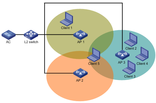
To implement WLAN load balancing among specific APs, the APs must be managed by the same AC, and the clients can discover the APs. As shown in Figure 1, load balancing is enabled on AP 1, AP 2, and AP 3 that are managed by the same AC. AP 3 has reached its maximum load. When Client 5 tries to associate with AP 3, the AC rejects the association request and directs Client 5 to AP 1 or AP 2. However, if Client 5 can only discover AP 3, it continues to send association requests to AP 3. If the number of times that AP 3 rejects Client 5 reaches the specified maximum number of denials for association requests, AP 3 accepts Client 5's association request.
Figure 1 Implementation prerequisites
Work mechanism
The AC performs load balancing when the following conditions are met:
· The load of an AP reaches the threshold.
· The load gap between the AP and the AP that has the lightest load reaches the load gap threshold.
When the load and load gap for the AP reach their respective threshold, the AP rejects the association request of a client. If the number of times that the AP rejects the client reaches the specified maximum number of denials for association requests, the AP accepts the client's association request.
Load balancing modes
The AC supports session-mode, traffic-mode, and bandwidth-mode load balancing. It performs load balancing of a specific mode when the following conditions are met:
· The specified session/traffic/bandwidth threshold is reached.
· The specified session/traffic/bandwidth gap threshold is reached.
Session-mode load balancing
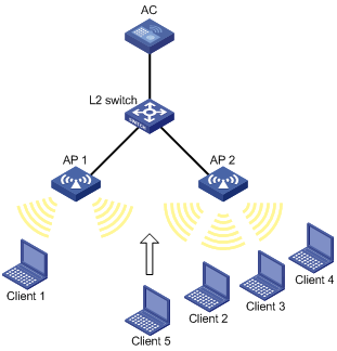
As shown in Figure 2, Client 1 associates with AP 1, and Client 2 through Client 4 associate with AP 2. Assume that the session threshold and session gap threshold are set to 3 and 2, respectively. When Client 5 tries to associate with AP 2, AP 2 rejects the request because both the session threshold and session gap threshold are reached.
Figure 2 Session-mode load balancing
Traffic-mode load balancing
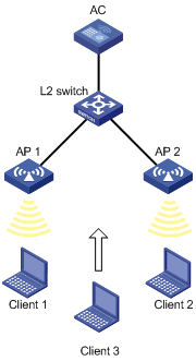
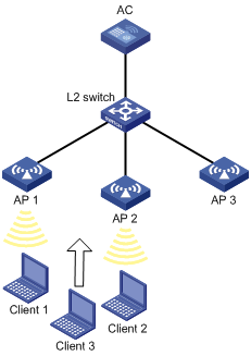
As shown in Figure 3, Client 1 associates with AP 1, and Client 2 associates with AP 2. When the traffic of AP 1 and the traffic gap between AP 1 and AP 2 reach their respective threshold, AP 1 rejects the association request from Client 3.
Figure 3 Traffic-mode load balancing

Bandwidth-mode load balancing
As shown in Figure 4, Client 1 associates with AP 1, and Client 2 associates with AP 2. When the bandwidth of AP 1 and the bandwidth gap between AP 1 and AP 2 reach their respective thresholds, AP 1 rejects the association request from Client 3.
Figure 4 Bandwidth-mode load balancing
Load balancing types
The AC supports the following load balancing types:
· Radio based—The AC determines the APs that will participate in load balancing based on the neighbor reports of the APs. The neighbor report of an AP records the MAC address and RSSI value of each client that is detected by the AP. The AC determines that an AP will participate in load balancing when either of the following conditions is met:
¡ A client requests to associate with the AP and the AP detects that RSSI of the client is lower than the RSSI threshold.
¡ The AP detects that a client's RSSI has reached the RSSI threshold but the client does not request to associate with the AP.
· Load balancing group based—You add the radios of desired APs to a load balancing group. The AC does not perform load balancing on radios that do not belong to the load balancing group.
Configuration task list
|
Tasks at a glance |
Remarks |
|
(Required.) Enabling WLAN load balancing |
N/A |
|
(Required.) Setting a load balancing mode |
N/A |
|
(Optional.) Configuring a load balancing group |
If you do not create any load balancing groups, the AC performs radio-based load balancing. |
|
(Optional.) Configuring load balancing parameters |
N/A |
|
(Optional.) Enabling SNMP notifications for WLAN load balancing |
N/A |
Configuring WLAN load balancing
Before you configure load balancing, make sure the fast association function is disabled. For more information about fast association, see "Configuring WLAN access."
Enabling WLAN load balancing
|
Step |
Command |
Remarks |
|
1. Enter system view. |
system-view |
N/A |
|
2. Enable WLAN load balancing. |
wlan load-balance enable |
By default, WLAN load balancing is disabled. |
Setting a load balancing mode
|
Command |
Remarks |
|
|
1. Enter system view. |
system-view |
N/A |
|
2. Set a load balancing mode. |
· Set session-mode load balancing: · Set traffic-mode load balancing: · Set bandwidth-mode load balancing: |
By default, session-mode load balancing is used. |
Configuring a load balancing group
|
Step |
Command |
Remarks |
|
1. Enter system view. |
system-view |
N/A |
|
2. Create a load balancing group and enter its view. |
wlan load-balance group group-id |
By default, no load balancing group exists. |
|
3. Add a radio of an AP to the load balancing group. |
ap name ap-name radio radio-id |
By default, no radio exists in the load balancing group. |
|
4. (Optional.) Set a description for the load balancing group. |
description text |
By default, no description is set for the load balancing group. |
Configuring load balancing parameters
The following parameters affect load balancing calculation:
· Load balancing RSSI threshold—If an AP detects that the RSSI of a client is lower than the specified RSSI threshold, the AP performs either of the following operations:
¡ If multiple APs can detect the client, the AP participates in load balancing only when the client requests to associate with the AP.
¡ If only this AP can detect the client, the AP decreases the maximum number of denials to 1 so that the client has more chances to associate with the AP.
· Maximum number of denials for association requests—If the number of times that an AP rejects a client reaches the specified maximum number of denials for association requests, the AP accepts the association request of the client.
To configure load balancing parameters:
|
Step |
Command |
Remarks |
|
1. Enter system view. |
system-view |
N/A |
|
2. Set the RSSI threshold. |
wlan load-balance rssi-threshold rssi-threshold |
By default, the RSSI threshold is 25. |
|
3. Set the maximum number of denials for association requests. |
wlan load-balance access-denial access-denial |
By default, the maximum number of denials is 10 for association requests. |
Enabling SNMP notifications for WLAN load balancing
To report critical WLAN load balancing events to an NMS, enable SNMP notifications for WLAN load balancing. For WLAN load balancing event notifications to be sent correctly, you must also configure SNMP as described in Network Management and Monitoring Configuration Guide.
To enable SNMP notifications for WLAN load balancing:
|
Step |
Command |
Remarks |
|
1. Enter system view. |
system-view |
N/A |
|
2. Enable SNMP notifications for WLAN load balancing. |
snmp-agent trap enable wlan load-balance |
By default, SNMP notifications for WLAN load balancing are disabled. |
Displaying and maintaining WLAN load balancing
Execute the display command in any view.
|
Task |
Command |
|
Display load balancing group information. |
display wlan load-balance group { group-id | all } |
WLAN load balancing configuration examples (for radios)
Configuring session-mode load balancing
Network requirements
As shown in Figure 5, AP 1 and AP 2 are managed by the AC and the clients can discover the APs.
Configure the AC to perform session-mode load balancing on AP 1 and AP 2 when the following conditions are met:
· The number of sessions on one AP reaches 3.
· The session gap between the APs reaches 2.
Configuration procedure
# Create wireless service template 1, and set its SSID to session-balance.
<AC> system-view
[AC] wlan service-template 1
[AC-wlan-st-1] ssid session-balance
[AC-wlan-st-1] service-template enable
[AC-wlan-st-1] quit
# Create the AP template ap1, and specify the model and serial ID.
[AC] wlan ap ap1 model WA4320i-ACN
[AC-wlan-ap-ap1] serial-id 210235A29G007C000020
# Bind service template 1 to radio 2 of AP 1.
[AC-wlan-ap-ap1] radio 2
[AC-wlan-ap-ap1-radio-2] service-template 1
[AC-wlan-ap-ap1-radio-2] radio enable
[AC-wlan-ap-ap1-radio-2] quit
[AC-wlan-ap-ap1] quit
# Create the AP template ap2, and specify the model and serial ID.
[AC] wlan ap ap2 model WA4320i-ACN
[AC-wlan-ap-ap2] serial-id 210235A29G007C000021
# Bind service template 1 to radio 2 of AP 2.
[AC-wlan-ap-ap2] radio 2
[AC-wlan-ap-ap2-radio-2] service-template 1
[AC-wlan-ap-ap2-radio-2] radio enable
[AC-wlan-ap-ap2-radio-2] quit
[AC-wlan-ap-ap2] quit
# Set the load balancing mode to session mode, and set the session threshold and session gap threshold to 3 and 2, respectively.
[AC] wlan load-balance mode session 3 gap 2
# Enable WLAN load balancing.
[AC] wlan load-balance enable
Verifying the configuration
# Verify that the AC performs session-mode load balancing for AP 1 and AP 2 when the following conditions are met:
· The number of sessions on one AP reaches 3.
· The session gap between the APs reaches 2. (Details not shown.)
# Verify that AP 1 and AP 2 are load balanced by using the display wlan client command. (Details not shown.)
Configuring traffic-mode load balancing
Network requirements
As shown in Figure 6, AP 1 and AP 2 are managed by the AC and the clients can discover the APs. The maximum bandwidth for each AP is 150 Mbps.
Configure the AC to perform traffic-mode load balancing on AP 1 and AP 2 when the following conditions are met:
· The traffic of one AP reaches 30 Mbps (20% of the maximum bandwidth).
· The traffic gap between the APs reaches 15 Mbps (10% of the maximum bandwidth).

Configuration procedure
# Create wireless service template 1, and set its SSID to traffic-balance.
<AC> system-view
[AC] wlan service-template 1
[AC-wlan-st-1] ssid traffic-balance
[AC-wlan-st-1] service-template enable
[AC-wlan-st-1] quit
# Create the AP template ap1, and specify the model and serial ID.
[AC] wlan ap ap1 model WA4320i-ACN
[AC-wlan-ap-ap1] serial-id 210235A29G007C000020
# Bind service template 1 to radio 2 of AP 1.
[AC-wlan-ap-ap1] radio 2
[AC-wlan-ap-ap1-radio-2] service-template 1
[AC-wlan-ap-ap1-radio-2] radio enable
[AC-wlan-ap-ap1-radio-2] quit
[AC-wlan-ap-ap1] quit
# Create the AP template ap2, and specify the model and serial ID.
[AC] wlan ap ap2 model WA4320i-ACN
[AC-wlan-ap-ap2] serial-id 210235A29G007C000021
# Bind service template 1 to radio 2 of AP 2.
[AC-wlan-ap-ap2] radio 2
[AC-wlan-ap-ap2-radio-2] service-template 1
[AC-wlan-ap-ap2-radio-2] radio enable
[AC-wlan-ap-ap2-radio-2] quit
[AC-wlan-ap-ap2] quit
# Set the load balancing mode to traffic mode, and set the traffic threshold and traffic gap threshold to 20% and 10%, respectively.
[AC] wlan load-balance mode traffic 20 gap 10
# Enable WLAN load balancing.
[AC] wlan load-balance enable
Verifying the configuration
# Verify that the AC performs traffic-mode load balancing for AP 1 and AP 2 when the following conditions are met:
· The traffic of one AP reaches 30 Mbps.
· The traffic gap between the APs reaches 15 Mbps. (Details not shown.)
# Verify that AP 1 and AP 2 are load balanced by using the display wlan client command. (Details not shown.)
Configuring bandwidth-mode load balancing
Network requirements
As shown in Figure 7, AP 1 and AP 2 are managed by the AC and the clients can discover the APs.
Configure the AC to perform bandwidth-mode load balancing on AP 1 and AP 2 when the following conditions are met:
· The bandwidth of one AP reaches 12 Mbps.
· The bandwidth gap between the APs reaches 3 Mbps.
Configuration procedure
# Create wireless service template 1, and set its SSID to bandwidth-balance.
<AC> system-view
[AC] wlan service-template 1
[AC-wlan-st-1] ssid bandwidth-balance
[AC-wlan-st-1] service-template enable
[AC-wlan-st-1] quit
# Create the AP template ap1, and specify the model and serial ID.
[AC] wlan ap ap1 model WA4320i-ACN
[AC-wlan-ap-ap1] serial-id 210235A29G007C000020
# Bind service template 1 to radio 2 of AP 1.
[AC-wlan-ap-ap1] radio 2
[AC-wlan-ap-ap1-radio-2] service-template 1
[AC-wlan-ap-ap1-radio-2] radio enable
[AC-wlan-ap-ap1-radio-2] quit
[AC-wlan-ap-ap1] quit
# Create the AP template ap2, and specify the model and serial ID.
[AC] wlan ap ap2 model WA4320i-ACN
[AC-wlan-ap-ap2] serial-id 210235A29G007C000021
# Bind service template 1 to radio 2 of AP 2.
[AC-wlan-ap-ap2] radio 2
[AC-wlan-ap-ap2-radio-2] service-template 1
[AC-wlan-ap-ap2-radio-2] radio enable
[AC-wlan-ap-ap2-radio-2] quit
[AC-wlan-ap-ap2] quit
# Set the load balancing mode to bandwidth mode, and set the bandwidth threshold and bandwidth gap threshold to 12 Mbps and 3 Mbps, respectively.
[AC] wlan load-balance mode bandwidth 12 gap 3
# Enable WLAN load balancing.
[AC] wlan load-balance enable
Verifying the configuration
# Verify that the AC performs bandwidth-mode load balancing for AP 1 and AP 2 when the following conditions are met:
· The bandwidth of one AP reaches 12 Mbps.
· The bandwidth gap between the APs reaches 3 Mbps. (Details not shown.)
# Verify that AP 1 and AP 2 are load balanced by using the display wlan client command. (Details not shown.)
WLAN load balancing configuration examples (for a load balancing group)
Configuring session-mode load balancing
Network requirements
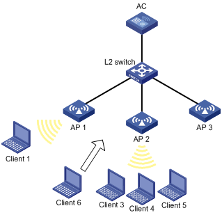
As shown in Figure 8, AP 1, AP 2, and AP 3 are managed by the AC and the clients can discover the APs.
Configure the AC to perform session-mode load balancing on radio 2 of AP 1 and radio 2 of AP 2 when the following conditions are met:
· The number of sessions on one radio reaches 3.
· The session gap between the radios reaches 2.
Configuration procedure
# Create wireless service template 1, and set its SSID to session-balance.
<AC> system-view
[AC] wlan service-template 1
[AC-wlan-st-1] ssid session-balance
[AC-wlan-st-1] service-template enable
[AC-wlan-st-1] quit
# Create the AP template ap1, and specify the model and serial ID.
[AC] wlan ap ap1 model WA4320i-ACN
[AC-wlan-ap-ap1] serial-id 210235A29G007C000020
# Bind service template 1 to radio 2 of AP 1.
[AC-wlan-ap-ap1] radio 2
[AC-wlan-ap-ap1-radio-2] service-template 1
[AC-wlan-ap-ap1-radio-2] radio enable
[AC-wlan-ap-ap1-radio-2] quit
[AC-wlan-ap-ap1] quit
# Create the AP template ap2, and specify the model and serial ID.
[AC] wlan ap ap2 model WA4320i-ACN
[AC-wlan-ap-ap2] serial-id 210235A29G007C000021
# Bind service template 1 to radio 2 of AP 2.
[AC-wlan-ap-ap2] radio 2
[AC-wlan-ap-ap2-radio-2] service-template 1
[AC-wlan-ap-ap2-radio-2] radio enable
[AC-wlan-ap-ap2-radio-2] quit
[AC-wlan-ap-ap2] quit
# Create the AP template ap3, and specify the model and serial ID.
[AC] wlan ap ap3 model WA4320i-ACN
[AC-wlan-ap-ap3] serial-id 210235A29G007C000022
# Bind service template 1 to radio 2 of AP 3.
[AC-wlan-ap-ap3] radio 2
[AC-wlan-ap-ap3-radio-2] service-template 1
[AC-wlan-ap-ap3-radio-2] radio enable
[AC-wlan-ap-ap3-radio-2] quit
[AC-wlan-ap-ap3] quit
# Set the load balancing mode to session mode, and set the session threshold and session gap threshold to 3 and 2, respectively.
[AC] wlan load-balance mode session 3 gap 2
# Create load balancing group 1.
[AC] wlan load-balance group 1
# Add radio 2 of AP 1 and radio 2 of AP 2 to load balancing group 1.
[AC-wlan-lb-group-1] ap name ap1 radio 2
[AC-wlan-lb-group-1] ap name ap2 radio 2
# Enable WLAN load balancing.
[AC] wlan load-balance enable
Verifying the configuration
# Verify that the AC performs session-mode load balancing for radio 2 of AP 1 and radio 2 of AP 2 when the following conditions are met:
· The number of sessions on one radio reaches 3.
· The session gap between the radios reaches 2. (Details not shown.)
# Verify that AP 1 and AP 2 are load balanced by using the display wlan client command. (Details not shown.)
Configuring traffic-mode load balancing
Network requirements
As shown in Figure 9, AP 1, AP 2, and AP 3 are managed by the AC and the clients can discover the APs. The maximum bandwidth for each AP is 150 Mbps.
Configure the AC to perform traffic-mode load balancing on radio 2 of AP 1 and radio 2 of AP 2 when the following conditions are met:
· The traffic of one radio reaches 30 Mbps (20% of the maximum bandwidth).
· The traffic gap between the radios reaches 15 Mbps (10% of the maximum bandwidth).

Configuration procedure
# Create wireless service template 1, and set its SSID to traffic-balance.
<AC> system
[AC] wlan service-template 1
[AC-wlan-st-1] ssid traffic-balance
[AC-wlan-st-1] service-template enable
[AC-wlan-st-1] quit
# Create the AP template ap1, and specify the model and serial ID.
[AC] wlan ap ap1 model WA4320i-ACN
[AC-wlan-ap-ap1] serial-id 210235A29G007C000020
# Bind service template 1 to radio 2 of AP 1.
[AC-wlan-ap-ap1] radio 2
[AC-wlan-ap-ap1-radio-2] service-template 1
[AC-wlan-ap-ap1-radio-2] radio enable
[AC-wlan-ap-ap1-radio-2] quit
[AC-wlan-ap-ap1] quit
# Create the AP template ap2, and specify the model and serial ID.
[AC] wlan ap ap2 model WA4320i-ACN
[AC-wlan-ap-ap2] serial-id 210235A29G007C000021
# Bind service template 1 to radio 2 of AP 2.
[AC-wlan-ap-ap2] radio 2
[AC-wlan-ap-ap2-radio-2] service-template 1
[AC-wlan-ap-ap2-radio-2] radio enable
[AC-wlan-ap-ap2-radio-2] quit
[AC-wlan-ap-ap2] quit
# Create the AP template ap3, and specify the model and serial ID.
[AC] wlan ap ap3 model WA4320i-ACN
[AC-wlan-ap-ap3] serial-id 210235A29G007C000022
# Bind service template 1 to radio 2 of AP 3.
[AC-wlan-ap-ap3] radio 2
[AC-wlan-ap-ap3-radio-2] service-template 1
[AC-wlan-ap-ap3-radio-2] radio enable
[AC-wlan-ap-ap3-radio-2] quit
[AC-wlan-ap-ap3] quit
# Set the load balancing mode to traffic mode, and set the traffic threshold and traffic gap threshold to 20% and 10%, respectively.
[AC] wlan load-balance mode traffic 20 gap 10
# Create load balancing group 1.
[AC] wlan load-balance group 1
# Add radio 2 of AP 1 and radio 2 of AP 2 to load balancing group 1.
[AC-wlan-lb-group-1] ap name ap1 radio 2
[AC-wlan-lb-group-1] ap name ap2 radio 2
[AC-wlan-lb-group-1] quit
# Enable WLAN load balancing.
[AC] wlan load-balance enable
Verifying the configuration
# Verify that the AC performs traffic-mode load balancing for radio 2 of AP 1 and radio 2 of AP 2 when the following conditions are met:
· The traffic of one radio reaches 30 Mbps.
· The traffic gap between the radios reaches 15 Mbps. (Details not shown.)
# Verify that AP 1 and AP 2 are load balanced by using the display wlan client command. (Details not shown.)
Configuring bandwidth-mode load balancing
Network requirements
As shown in Figure 10, AP 1, AP 2, and AP 3 are managed by the AC and the clients can discover the APs.
Configure the AC to perform bandwidth-mode load balancing on radio 2 of AP 1 and radio 2 of AP 2 when the following conditions are met:
· The bandwidth of one radio reaches 12 Mbps.
· The bandwidth gap between the radios reaches 3 Mbps.
Configuration procedure
# Create wireless service template 1, and set its SSID to bandwidth-balance.
<AC> system
[AC] wlan service-template 1
[AC-wlan-st-1] ssid bandwidth-balance
[AC-wlan-st-1] service-template enable
[AC-wlan-st-1] quit
# Create the AP template ap1, and specify the model and serial ID.
[AC] wlan ap ap1 model WA4320i-ACN
[AC-wlan-ap-ap1] serial-id 210235A29G007C000020
# Bind service template 1 to radio 2 of AP 1.
[AC-wlan-ap-ap1] radio 2
[AC-wlan-ap-ap1-radio-2] service-template 1
[AC-wlan-ap-ap1-radio-2] radio enable
[AC-wlan-ap-ap1-radio-2] quit
[AC-wlan-ap-ap1] quit
# Create the AP template ap2, and specify the model and serial ID.
[AC] wlan ap ap2 model WA4320i-ACN
[AC-wlan-ap-ap2] serial-id 210235A29G007C000021
# Bind service template 1 to radio 2 of AP 2.
[AC-wlan-ap-ap2] radio 2
[AC-wlan-ap-ap2-radio-2] service-template 1
[AC-wlan-ap-ap2-radio-2] radio enable
[AC-wlan-ap-ap2-radio-2] quit
[AC-wlan-ap-ap2] quit
# Create the AP template ap3, and specify the model and serial ID.
[AC] wlan ap ap3 model WA4320i-ACN
[AC-wlan-ap-ap3] serial-id 210235A29G007C000022
# Bind service template 1 to radio 2 of AP 3.
[AC-wlan-ap-ap3] radio 2
[AC-wlan-ap-ap3-radio-2] service-template 1
[AC-wlan-ap-ap3-radio-2] radio enable
[AC-wlan-ap-ap3-radio-2] quit
[AC-wlan-ap-ap3] quit
# Set the load balancing mode to bandwidth mode, and set the bandwidth threshold and bandwidth gap threshold to 12 Mbps and 3 Mbps, respectively.
[AC] wlan load-balance mode bandwidth 12 gap 3
# Create load balancing group 1.
[AC] wlan load-balance group 1
# Add radio 2 of AP 1 and radio 2 of AP 2 to load balancing group 1.
[AC-wlan-lb-group-1] ap name ap1 radio 2
[AC-wlan-lb-group-1] ap name ap2 radio 2
[AC-wlan-lb-group-1] quit
# Enable WLAN load balancing.
[AC] wlan load-balance enable
Verifying the configuration
# Verify that the AC performs bandwidth-mode load balancing for radio 2 of AP 1 and radio 2 of AP 2 when the following conditions are met:
· The bandwidth of one radio reaches 12 Mbps.
· The bandwidth gap between the radios reaches 3 Mbps. (Details not shown.)
# Verify that AP 1 and AP 2 are load balanced by using the display wlan client command. (Details not shown.)