- Table of Contents
-
- 02-WLAN
- 00-Preface
- 01-AP management configuration
- 02-Radio management configuration
- 03-WLAN access configuration
- 04-WLAN security configuration
- 05-WLAN authentication configuration
- 06-WIPS configuration
- 07-WLAN QoS configuration
- 08-WLAN roaming configuration
- 09-WLAN load balancing configuration
- 10-WLAN radio resource measurement configuration
- 11-Channel scanning configuration
- 12-Band navigation configuration
- 13-WLAN high availability configuration
- 14-802.11r configuration
- 15-Wireless location configuration
- 16-Hotspot 2.0 configuration
- 17-WLAN RRM configuration
- 18-WT configuration
- 19-IoT AP configuration
- 20-CM tunnel configuration
- 21-Cloud connection configuration
- 22-WLAN IP snooping configuration
- 23-WLAN fast forwarding configuration
- Related Documents
-
| Title | Size | Download |
|---|---|---|
| 01-AP management configuration | 383.33 KB |
Configuring CAPWAP tunnel establishment
Setting the AP connection priority for the AC
Enabling the AC to respond to only unicast discovery requests
Configuring AC rediscovery in AP view
Configuring AC rediscovery in AP group view
Configuring AC rediscovery in global configuration view
Configuring the mapping between a software version and a hardware version of an AP model
Specifying the preferred location for the AC to obtain an AP image file
Configuring basic VLAN settings
Configuring remote configuration assignment
Configuring CAPWAP tunnel latency detection
Setting the control tunnel keepalive time for an AP
Setting the data tunnel keepalive time for an AP
Setting the maximum fragment size for CAPWAP packets
Setting the TCP MSS for CAPWAP tunnels
Configuring AC request retransmission
Configuring AC request retransmission in AP view
Configuring AC request retransmission in AP group view
Setting the statistics report interval
Setting the statistics report interval in AP view
Setting the statistics report interval in AP group view
Configuring remote AP in AP view
Configuring remote AP in AP group view
Configuring the default input power level
Configuration restrictions and guidelines
Configuring the default input power level in AP view
Configuring the default input power level in AP group's AP model view
Enabling or disabling USB interfaces for APs
Enabling or disabling USB interfaces in AP view
Enabling or disabling USB interfaces in AP group' AP model view
Managing the file system of an AP
Changing the interface type to GigabitEthernet
Enabling or disabling PoE for PIs
Configuration restrictions and guidelines
Configuring preprovisioned settings for an AP
Configuring network settings for an AP group
Assigning preprovisioned settings to APs
Configuring auto loading of preprovisioned settings
Configuration restrictions and guidelines
Displaying and maintaining AP management
Displaying AP management information
Clearing AP management information
AP management configuration examples
CAPWAP tunnel establishment through DHCP configuration example
CAPWAP tunnel establishment through DHCPv6 configuration example
CAPWAP tunnel establishment through DNS configuration example
Managing APs
Overview
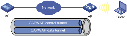
Managing a large number of APs is both time consuming and costly. The fit AP+AC network architecture enables an AC to establish Control And Provisioning of Wireless Access Points (CAPWAP) tunnels with a large number of APs for centralized AP management and maintenance.
CAPWAP tunnel
CAPWAP defines how an AP communicates with an AC. It provides a generic encapsulation and transport mechanism between AP and AC. CAPWAP uses UDP and supports both IPv4 and IPv6.
As shown in Figure 1, an AC and an AP establish a data tunnel to forward data packets and a control tunnel to forward control packets.
AC discovery
After starting up with zero configurations, an AP automatically creates VLAN-interface 1 and enables the DHCP client, DHCPv6 client, and DNS features on the interface. Then it obtains its own IP address from the DHCP server and discovers ACs by using the following methods:
· Static IP address:
If AC IP addresses have been manually configured for the AP, the AP sends a unicast discovery request to each AC IP address to discover ACs.
· DHCP options:
a. The AP obtains AC IPv4 addresses from Option 138, Option 43, and IPv6 addresses from Option 52 sent from the DHCP server. It uses these addresses in descending order.
b. The AP sends a unicast discovery request to each received AC address to discover ACs.
For more information about DHCP options, see Layer 3—IP Services Configuration Guide.
· DNS:
a. The AP obtains the domain name suffix from the DHCP server.
b. The AP adds the suffix to the host name.
c. The DNS server translates the domain name into IP addresses.
d. The AP sends a unicast discovery request to each IP address to discover ACs.
For more information about DNS, see Layer 3—IP Services Configuration Guide.
· Broadcast:
The AP broadcasts discovery requests to IP address 255.255.255.255 to discover ACs.
· IPv4 multicast:
The AP sends multicast discovery requests to IPv4 address 224.0.1.140 to discover ACs.
· IPv6 multicast:
The AP sends multicast discovery requests to IPv6 address FF0E::18C to discover ACs.
The methods of static IP address, DHCPv4 options, broadcast, IPv4 multicast, IPv4 DNS, IPv6 multicast, DHCPv6 option, and IPv6 DNS are used in descending order.
The AP does not stop AC discovery until it establishes a CAPWAP tunnel with one of the discovered ACs.
CAPWAP tunnel establishment
Figure 2 Establishing a CAPWAP tunnel
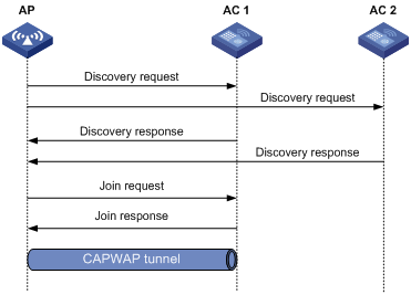
As shown in Figure 2, the AP and an AC establish a CAPWAP tunnel by using the following procedure:
1. The AP sends a discovery request to each AC to discover ACs.
2. Upon receiving the discovery request, an AC determines whether to send a discovery response by performing the following steps:
a. Identifies whether the discovery request is a unicast packet.
- Unicast packet—The AC proceeds to step b.
- Broadcast or multicast packet—The AC proceeds to step b if it is disabled with the feature of responding to only unicast discovery requests. If this feature is enabled, the AC does not send a discovery response.
- If manual AP configuration exists, the AC sends a discovery response to the AP. The discovery response contains information about whether the AC has the manual configuration for the AP, the AP connection priority, and the AC's load status.
- If no manual AP configuration exists, the AC proceeds to step c.
c. Identifies whether auto AP is enabled.
- If auto AP is enabled, the AC sends a discovery response to the AP. The discovery response contains the enabling status of auto AP, AP connection priority, and AC's load information.
- If auto AP is disabled, the AP does not send a discovery response.
3. Upon receiving the discovery responses, the AP selects the optimal AC in descending order.
¡ AC that saves information about the AP.
¡ AC where the auto AP feature is enabled.
¡ AC with higher AP connection priority.
¡ AC with the lighter load.
4. The AP sends a join request to the optimal AC.
5. After receiving the join request, the AC examines information in the request to determine whether to provide access services to the AP and sends a join response.
6. After receiving the join response, the AP examines the result code in the response:
¡ If the result code represents failure, the AP does not establish a CAPWAP tunnel with the AC.
¡ If the result code represents success, the AP establishes a CAPWAP tunnel with the AC.
AC rediscovery
An AC enabled with AC rediscovery will add the CAPWAP Control IP Address message element to the discovery responses sent to APs. Upon receiving such a discovery response, an AP establishes a CAPWAP tunnel by following this procedure:
1. Examines whether a discovery request has been sent to the IP address specified in the CAPWAP Control IP Address message element.
2. Performs either of the following operations:
¡ Sends a join request to the specified IP address representing the optimal AC for CAPWAP establishment if a discovery request has been sent.
¡ Sends a discovery request to each specified IP address to initiate a new AC discovery process if a discovery request has not been sent.
An AC disabled with AC rediscovery does not add the CAPWAP Control IP Address message element in discovery responses sent to APs. APs that receive the discovery responses will send join requests to the source IP address of the discovery responses to establish CAPWAP tunnels with the AC.
AP configuration methods
You can configure APs by using either of the following methods:
· Configure APs one by one in AP view.
· Assign APs to an AP group and configure the AP group in AP group view.
· Configure all APs in global configuration view.
For an AP, the priorities of the configuration in AP view, AP group view, and global configuration view are in descending order.
APDB
The Access Point Information Database (APDB) on an AC stores the following AP information:
· AP models.
· Hardware version and software version mappings.
· Information about radios supported by AP models.
¡ Number of radios.
¡ Radio type.
¡ Valid region code.
¡ Valid antenna type.
¡ Maximum transmission power.
The AC can establish a CAPWAP tunnel with an AP only when the APDB contains the corresponding AP model information.
You can use the system script and user scripts to manage data in the APDB. The system script is released with the AC software version, and it is automatically loaded each time the AC starts. If you need to add new AP models, upgrade the AC software version (see Fundamentals Configuration Guide) or create a user script and load it on the AC (see "Loading an APDB user script").
Protocols and standards
· RFC 5415, Control And Provisioning of Wireless Access Points (CAPWAP) Protocol Specification
· RFC 5417, Control And Provisioning of Wireless Access Points (CAPWAP) Access Controller DHCP Option
Configuration task list
|
Tasks at a glance |
|
(Required.) Configuring CAPWAP tunnel establishment |
|
(Optional.) Configuring AC rediscovery |
|
(Optional.) Upgrading APs' software |
|
(Optional.) Configuring VLANs for APs |
|
(Optional.) Configuring a CAPWAP tunnel |
|
(Optional.) Configuring AC request retransmission |
|
(Optional.) Setting the statistics report interval |
|
(Optional.) Configuring remote AP |
|
(Optional.) Configuring the default input power level |
|
(Optional.) Enabling or disabling USB interfaces for APs |
|
(Optional.) Resetting APs |
|
(Optional.) Renaming a manual AP |
|
(Optional.) Managing the file system of an AP |
|
(Optional.) Managing AP interfaces |
|
(Optional.) Configuring an AP group |
|
(Optional.) Preprovisioning APs |
|
(Optional.) Enabling SNMP notifications |
|
(Optional.) Loading an APDB user script |
Configuration prerequisites
Before you manage APs, complete the following tasks:
· Create a DHCP address pool on the DHCP server to assign IP addresses to APs.
· If DHCP options are used for AC discovery, configure Option 138, Option 43, or Option 52 in the specified DHCP address pool on the DHCP server.
· If DNS is used for AC discovery, configure the IP address of the DNS server and the AC domain name suffix in the specified DHCP address pool on the DHCP server. Then configure the mapping between the domain name and the AC IP address on the DNS server.
· Make sure the APs and the AC can reach each other.
For more information about DHCP and DNS, see Layer 3—IP Services Configuration Guide.
Configuring CAPWAP tunnel establishment
Creating a manual AP
You can create a manual AP on the AC according to the AP model, serial ID, and MAC address of the AP you are using. An AP prefers to establish a CAPWAP tunnel with an AC that saves the manual AP configuration.
To create a manual AP:
|
Step |
Command |
Remarks |
|
1. Enter system view. |
system-view |
|
|
2. Create a manual AP and enter its view. |
wlan ap ap-name [ model model-name ] |
By default, no manual AP exists. You must specify the model name when you create an AP. |
|
3. Specify the serial ID or the MAC address for the AP. |
· Specify the serial ID for the AP: · Specify the MAC address for the AP: |
Use either command. |
|
4. (Optional.) Set a description for the AP. |
description text |
By default, no description is set for an AP. |
Managing auto APs
The auto AP feature enables APs to connect to an AC without manual AP configuration. The AC names auto APs by their MAC addresses. This feature simplifies configuration when you deploy a large number of APs in a WLAN.
Enabling the auto AP feature
|
Step |
Command |
Remarks |
|
1. Enter system view. |
system-view |
N/A |
|
2. Enable the auto AP feature. |
wlan auto-ap enable |
By default, the auto AP feature is disabled. |
Converting auto APs to manual APs
You must convert auto APs to manual APs after they come online because of the following reasons:
· You can modify auto AP configuration only when they are converted to manual APs.
· For security purposes, auto APs can re-associate with the AC upon an AC reboot or CAPWAP tunnel termination only when they are converted to manual APs.
To convert auto APs to manual APs:
|
Step |
Command |
Remarks |
|
1. Enter system view. |
system-view |
N/A |
|
2. Convert auto APs to manual APs. |
· Convert online auto APs to manual APs: · Convert auto APs to manual APs
automatically after auto APs come online: |
Use either command. By default, auto APs are not converted to manual APs. The wlan auto-persistent enable command does not take effect on auto APs that are already online. |
Setting the AP connection priority for the AC
ACs put their AP connection priorities in discovery responses. An AP prefers to establish a CAPWAP tunnel with an AC that has higher connection priority when either of the following conditions exists:
· Multiple ACs have manual AP configuration for the AP.
· No AC has manual AP configuration for the AP, but multiple ACs are enabled with the auto AP feature.
Setting the AP connection priority in AP view
|
Step |
Command |
Remarks |
|
1. Enter system view. |
system-view |
N/A |
|
2. Enter AP view. |
wlan ap ap-name [ model model-name ] |
N/A |
|
3. Set the AP connection priority for the AC. |
priority priority |
By default, an AP uses the configuration in AP group view. A larger number represents a higher priority. |
Setting the AP connection priority in AP group view
|
Step |
Command |
Remarks |
|
1. Enter system view. |
system-view |
N/A |
|
2. Enter AP group view. |
wlan ap-group group-name |
N/A |
|
3. Set the AP connection priority for the AC. |
priority priority |
The default setting is 4. A larger number represents a higher priority. |
Enabling the AC to respond to only unicast discovery requests
An AP can send unicast, multicast, and broadcast discovery requests to discover ACs. This feature enables an AC to respond to only unicast discovery requests.
To enable the AC to respond to only unicast discovery requests:
|
Step |
Command |
Remarks |
|
1. Enter system view. |
system-view |
N/A |
|
2. Enable the AC to respond to only unicast discovery requests. |
wlan capwap discovery-policy unicast |
By default, the AC can respond to unicast, multicast, and broadcast discovery requests. |
Configuring AC rediscovery
Configuring AC rediscovery in AP view
|
Step |
Command |
Remarks |
|
1. Enter system view. |
system-view |
N/A |
|
2. Enter AP view. |
wlan ap ap-name [ model model-name ] |
N/A |
|
control-address { disable | enable } |
By default, an AP uses the configuration in AP group view. If no configuration exists in AP group view, the AP uses the configuration in global configuration view. |
|
|
4. Specify the IP address to be carried in the CAPWAP Control IP Address message element. |
control-address { ip ipv4-address | ipv6 ipv6-address } |
By default, an AP uses the configuration in AP group view. If no configuration exists in AP group view, the AP uses the configuration in global configuration view. You can specify a maximum of three IPv4 or IPv6 addresses to be added in the CAPWAP Control IP Address message element. |
Configuring AC rediscovery in AP group view
|
Step |
Command |
Remarks |
|
1. Enter system view. |
system-view |
N/A |
|
2. Enter AP group view. |
wlan ap-group group-name |
N/A |
|
3. Configure AC rediscovery. |
control-address { disable | enable } |
By default, an AP uses the configuration in global configuration view. |
|
4. Specify the IP address to be carried in the CAPWAP Control IP Address message element. |
control-address { ip ipv4-address | ipv6 ipv6-address } |
By default, an AP uses the configuration in global configuration view. You can specify a maximum of three IPv4 or IPv6 addresses to be added in the CAPWAP Control IP Address message element. |
Configuring AC rediscovery in global configuration view
|
Step |
Command |
Remarks |
|
1. Enter system view. |
system-view |
N/A |
|
2. Enter global configuration view. |
wlan global-configuration |
N/A |
|
3. Configure AC rediscovery. |
control-address { disable | enable } |
By default, AC rediscovery is disabled. |
|
4. Specify the IP address to be carried in the CAPWAP Control IP Address message element. |
control-address { ip ipv4-address | ipv6 ipv6-address } |
By default, the IP address in the element is the AC's IP address. You can specify a maximum of three IPv4 or IPv6 addresses to be added in the CAPWAP Control IP Address message element. |
Upgrading APs' software
Overview
Software upgrade for an AP proceeds as follows:
1. The AP reports the software version and AP model information to the AC.
2. The AC examines the received AP software version.
¡ If a match is found, the AC establishes a CAPWAP tunnel with the AP.
¡ If no match is found, the AC sends a message that notifies the AP of the AP software version inconsistency.
3. Upon receiving the inconsistency message, the AP requests a software version from the AC.
4. The AC assigns the software version to the AP after receiving the request.
5. The AP upgrades the software version, and restarts to establish a CAPWAP tunnel with the AC.
Configuring software upgrade
The AC examines the AP software version while establishing the CAPWAP tunnel only when software upgrade is enabled. If this feature is disabled, the AC does not examine the software version of the AP and directly establishes a CAPWAP tunnel with the AP.
Configuring software upgrade in AP view
|
Step |
Command |
Remarks |
|
1. Enter system view. |
system-view |
N/A |
|
2. Enter AP view. |
wlan ap ap-name [ model model-name ] |
N/A |
|
3. Configure software upgrade. |
firmware-upgrade { disable | enable } |
By default, an AP uses the configuration in AP group view. If no software upgrade configuration exists in AP group view, the AP uses the configuration in global configuration view. |
Configuring software upgrade in AP group view
|
Step |
Command |
Remarks |
|
1. Enter system view. |
system-view |
N/A |
|
2. Enter AP group view. |
wlan ap-group group-name |
N/A |
|
3. Configure software upgrade. |
firmware-upgrade { disable | enable } |
By default, an AP uses the configuration in global configuration view. |
Configuring software upgrade in global configuration view
|
Step |
Command |
Remarks |
|
1. Enter system view. |
system-view |
N/A |
|
2. Enter global configuration view. |
wlan global-configuration |
N/A |
|
3. Configure software upgrade. |
firmware-upgrade { disable | enable } |
By default, the software upgrade feature is enabled. |
Configuring the mapping between a software version and a hardware version of an AP model
|
|
CAUTION: To avoid CAPWAP tunnel establishment failure, use this feature under the guidance of H3C Support. |
Perform this task to configure the mapping between a software version and a hardware version of an AP model for software upgrade.
Perform this task only when the AP software version for an AP model stored in the APDB is inconsistent with the software version you expect for the AP model. To display the AP software version for each AP model in the APDB, use the display wlan ap-model command.
For example, the APDB has a hardware version and software version mapping entry (hardware version Ver.C and software version E2108) for AP model WA4320i-CAN. If you expect this AP to use software version E2105 when it comes online, perform the following steps:
1. Configure the mapping between software version E2105 and hardware version Ver.C of AP model WA4320i-ACN.
2. Save the AP image file of software version E2105 to the AC's local folder.
3. Configure the AC to prefer the AP image file stored in the local folder for software version assignment.
To configure the mapping between a software version and a hardware version of an AP model:
|
Step |
Command |
Remarks |
|
1. Enter system view. |
system-view |
N/A |
|
2. Configure the mapping between a software version and a hardware version of an AP model. |
wlan apdb model-name hardware-version software-version |
By default, the software version for a hardware version of an AP model is the software version that is stored in APDB user scripts. |
Specifying the preferred location for the AC to obtain an AP image file
The AC assigns an AP image file to an AP if the AP requests a software version during CAPWAP tunnel establishment. You can specify the preferred location as the AC's RAM or local folder for the AC to obtain an AP image file. If the AC cannot obtain an AP image file from the preferred location, it obtains an AP image file from the other location. If no AP image file exists, the AC fails to obtain an image file and cannot assign a software version to the AP.
Configuration restrictions and guidelines
When you specify the preferred image location for the AC to obtain an AP image file, follow these restrictions and guidelines:
· The AC can assign only .ipe AP image files to APs.
· If you specify the local folder, make sure the AC uses a CF card as the default file system and the AP image file is stored in the root directory of the file system on the AC.
Configuration procedure
To specify the preferred location for the AC to obtain an AP image file:
|
Step |
Command |
Remarks |
|
1. Enter system view. |
system-view |
N/A |
|
2. Specify the preferred location for the AC to obtain an AP image file. |
wlan image-load filepath { local | ram } |
By default, the AC prefers the AP image file stored in the RAM when assigning a software version to an AP. |
Configuring VLANs for APs
|
|
NOTE: Support for this feature depends on the AP model. |
Perform this task to enable the AC to assign VLAN settings to APs for packet forwarding and isolation. For example, when you enable an AP to forward client data traffic, you need to configure ports of the AP to allow client traffic from different VLANs.
For information about VLANs, see Layer 2—LAN Switching Configuration Guide. For information about client data traffic forwarder configuration, see "Configuring WLAN access."
Configuring basic VLAN settings
Configuring basic VLAN settings in AP view
|
Step |
Command |
Remarks |
|
1. Enter system view. |
system-view |
N/A |
|
2. Enter AP view. |
wlan ap ap-name [ model model-name ] |
N/A |
|
3. (Optional.) Create a VLAN and enter its view, or create a list of VLANs. |
vlan { vlan-id1 [ to vlan-id2 ] | all } |
By default, only VLAN 1 (the system default VLAN) exists. |
|
4. Enter VLAN view. |
vlan vlan-id |
Required if you create a list of VLANs. |
|
5. Assign a name to the VLAN. |
name text |
By default, an AP uses the configuration in AP group view. |
|
6. Configure the description of the VLAN. |
description text |
By default, an AP uses the configuration in AP group view. |
Configuring basic VLAN settings in AP group view
|
Step |
Command |
Remarks |
|
1. Enter system view. |
system-view |
N/A |
|
2. Enter AP group view. |
wlan ap-group group-name |
N/A |
|
3. (Optional.) Create a VLAN and enter its view, or create a list of VLANs. |
vlan { vlan-id1 [ to vlan-id2 ] | all } |
By default, only VLAN 1 (the system default VLAN) exists. |
|
4. Enter VLAN view. |
vlan vlan-id |
Required if you create a list of VLANs. |
|
5. Assign a name to the VLAN. |
name text |
By default, the name of a VLAN is VLAN vlan-id. The vlan-id argument specifies the VLAN ID in a four-digit format. If the VLAN ID has less than four digits, leading zeros are added. For example, the name of VLAN 100 is VLAN 0100. |
|
6. Configure the description of the VLAN. |
description text |
By default, the description of a VLAN is VLAN vlan-id. The vlan-id argument specifies the VLAN ID in a four-digit format. If the VLAN ID has less than four digits, leading zeros are added. For example, the default description of VLAN 100 is VLAN 0100. |
Configuring port-based VLANs
Assigning an access port to a VLAN
To assign an access port to a VLAN in an AP's Layer 2 Ethernet interface view:
|
Step |
Command |
Remarks |
|
1. Enter system view. |
system-view |
N/A |
|
2. Enter AP view. |
wlan ap ap-name [ model model-name ] |
N/A |
|
3. Enter Layer 2 Ethernet interface view. |
· Enter GigabitEthernet interface view: · Enter Smarterate-Ethernet interface
view: |
Use either command according to AP models and network requirements. |
|
4. Set the link type to access. |
port link-type access |
By default, a port uses the configuration in an AP group's Layer 2 Ethernet interface view. |
|
5. Assign the access port to a VLAN. |
port access vlan vlan-id |
By default, an access port uses the configuration in an AP group's Layer 2 Ethernet interface view. |
To assign an access port to a VLAN in an AP group's Layer 2 Ethernet interface view:
|
Step |
Command |
Remarks |
|
1. Enter system view. |
system-view |
N/A |
|
2. Enter AP group view. |
wlan ap-group group-name |
N/A |
|
3. Enter AP model view. |
ap-model ap-model |
N/A |
|
4. Enter Layer 2 Ethernet interface view. |
· Enter GigabitEthernet interface view: · Enter Smarterate-Ethernet interface
view: |
Use either command according to AP models and network requirements. |
|
5. Set the link type to access. |
port link-type access |
By default, all ports are access ports. |
|
6. Assign the access port to a VLAN. |
port access vlan vlan-id |
By default, an access port belongs to VLAN 1. |
Assigning a trunk port to VLANs
To assign a trunk port to VLANs in an AP's Layer 2 Ethernet interface view:
|
Step |
Command |
Remarks |
|
1. Enter system view. |
system-view |
N/A |
|
2. Enter AP view. |
wlan ap ap-name [ model model-name ] |
N/A |
|
3. Enter Layer 2 Ethernet interface view. |
· Enter GigabitEthernet interface view: · Enter Smarterate-Ethernet interface view: |
Use either command according to AP models and network requirements. |
|
4. Set the link type to trunk. |
port link-type trunk |
By default, a port uses the configuration in an AP group's Layer 2 Ethernet interface view. |
|
5. Assign the trunk port to the specified VLANs. |
port trunk permit vlan { vlan-id-list | all } |
By default, a trunk port uses the configuration in an AP group's Layer 2 Ethernet interface view. |
|
6. (Optional.) Set the PVID for the trunk port. |
port trunk pvid vlan vlan-id |
By default, a trunk port uses the configuration in an AP group's Layer 2 Ethernet interface view. |
To assign a trunk port to VLANs in an AP group's Layer 2 Ethernet interface view:
|
Step |
Command |
Remarks |
|
1. Enter system view. |
system-view |
N/A |
|
2. Enter AP group view. |
wlan ap-group group-name |
N/A |
|
3. Enter AP model view. |
ap-model ap-model |
N/A |
|
4. Enter Layer 2 Ethernet interface view. |
· Enter GigabitEthernet interface view: · Enter Smarterate-Ethernet interface view: |
Use a command according to AP models and network requirements. |
|
5. Set the link type to trunk. |
port link-type trunk |
By default, all ports are access ports. |
|
6. Assign the trunk port to the specified VLANs. |
port trunk permit vlan { vlan-id-list | all } |
By default, a trunk port permits only VLAN 1. |
|
7. (Optional.) Set the PVID for the trunk port. |
port trunk pvid vlan vlan-id |
The default setting is VLAN 1. |
Assigning a hybrid port to VLANs
To assign a hybrid port to VLANs in an AP's Layer 2 Ethernet interface view:
|
Step |
Command |
Remarks |
|
1. Enter system view. |
system-view |
N/A |
|
2. Enter AP view. |
wlan ap ap-name [ model model-name ] |
N/A |
|
3. Enter Layer 2 Ethernet interface view. |
· Enter GigabitEthernet interface view: · Enter Smarterate-Ethernet interface view: |
Use either command according to AP models and network requirements. |
|
4. Set the link type to hybrid. |
port link-type hybrid |
By default, a port uses the configuration in an AP group's Layer 2 Ethernet interface view. |
|
5. Assign the hybrid port to the specified VLANs. |
port hybrid vlan vlan-id-list { tagged | untagged } |
By default, a hybrid port uses the configuration in an AP group's Layer 2 Ethernet interface view. |
|
6. (Optional.) Set the PVID for the hybrid port. |
port hybrid pvid vlan vlan-id |
By default, a hybrid port uses the configuration in an AP group's Layer 2 Ethernet interface view. |
To assign a hybrid port to VLANs in an AP group's Layer 2 Ethernet interface view:
|
Step |
Command |
Remarks |
|
1. Enter system view. |
system-view |
N/A |
|
2. Enter AP group view. |
wlan ap-group group-name |
N/A |
|
3. Enter AP model view. |
ap-model ap-model |
N/A |
|
4. Enter Layer 2 Ethernet interface view. |
· Enter GigabitEthernet interface view: · Enter Smarterate-Ethernet interface view: |
Use either command according to AP models and network requirements. |
|
5. Set the link type to hybrid. |
port link-type hybrid |
By default, all ports are access ports. |
|
6. Assign the hybrid port to the specified VLANs. |
port hybrid vlan vlan-id-list { tagged | untagged } |
By default, a hybrid port is an untagged member of the VLAN to which the port belongs when its link type is access. |
|
7. (Optional.) Set the PVID for the hybrid port. |
port hybrid pvid vlan vlan-id |
By default, the PVID of a hybrid port is the ID of the VLAN to which the port belongs when its link type is access. |
Configuring remote configuration assignment
The AC assigns VLAN settings to an AP or an AP group only when this feature is enabled.
Configuring remote configuration assignment in AP view
|
Step |
Command |
Remarks |
|
1. Enter system view. |
system-view |
N/A |
|
2. Enter AP view. |
wlan ap ap-name [ model model-name ] |
N/A |
|
3. Configure remote configuration assignment. |
remote-configuration { disable | enable } |
By default, an AP uses the configuration in AP group view. |
Configuring remote configuration assignment in AP group view
|
Step |
Command |
Remarks |
|
1. Enter system view. |
system-view |
N/A |
|
2. Enter AP group view. |
wlan ap-group group-name |
N/A |
|
3. Configure remote configuration assignment. |
remote-configuration { disable | enable } |
By default, remote configuration assignment is disabled. |
Configuring a CAPWAP tunnel
Configuring CAPWAP tunnel latency detection
This feature enables an AC to detect the transmission latency of CAPWAP control frames or data frames from an AP to the AC and back.
This feature takes effect only on the master AC after a CAPWAP tunnel is established.
When an AP goes offline, CAPWAP tunnel latency detection automatically stops. To restart CAPWAP tunnel latency detection when the AP comes online, execute the tunnel latency-detect start command again.
To display CAPWAP tunnel latency information, use the display wlan tunnel latency ap name command.
To configure CAPWAP tunnel latency detection:
|
Step |
Command |
Remarks |
|
||
|
1. Enter system view. |
system-view |
N/A |
|
||
|
2. Enter AP view. |
wlan ap ap-name [ model model-name ] |
N/A |
|||
|
3. Configure CAPWAP tunnel latency detection. |
tunnel latency-detect { start | stop } |
By default, CAPWAP tunnel latency detection is not started. |
|
||
Setting the control tunnel keepalive time for an AP
An AP sends echo requests to the AC at the specified echo interval to identify whether the CAPWAP control tunnel is operating correctly. The AC responds by sending echo responses. If the AP does not receive any echo responses within the keepalive time, the AP terminates the connection. If the AC does not receive any echo requests within the keepalive time, the AC terminates the connection. The keepalive time is the echo interval multiplied by the maximum number of echo request transmission attempts.
Setting the control tunnel keepalive time for an AP in AP view
|
Step |
Command |
Remarks |
|
1. Enter system view. |
system-view |
N/A |
|
2. Enter AP view. |
wlan ap ap-name [ model model-name ] |
N/A |
|
3. Set the interval at which the AP sends echo requests. |
echo-interval interval |
By default, an AP uses the configuration in AP group view. |
|
4. Set the maximum number of echo request transmission attempts. |
echo-count count |
By default, an AP uses the configuration in AP group view. |
Setting the control tunnel keepalive time for APs in AP group view
|
Step |
Command |
Remarks |
|
1. Enter system view. |
system-view |
N/A |
|
2. Enter AP group view. |
wlan ap-group group-name |
N/A |
|
3. Set the interval at which the APs send echo requests. |
echo-interval interval |
The default setting is 10 seconds. |
|
4. Set the maximum number of echo request transmission attempts. |
echo-count count |
The default setting is 3. |
Setting the data tunnel keepalive time for an AP
An AP sends data channel keepalive packets to the AC at the specified keepalive time after a CAPWAP tunnel is established between the AP and the AC.
Setting the data tunnel keepalive time for an AP in AP view
|
Step |
Command |
Remarks |
|
1. Enter system view. |
system-view |
N/A |
|
2. Enter AP view. |
wlan ap ap-name [ model model-name ] |
N/A |
|
3. Set the data tunnel keepalive interval. |
keepalive-interval interval |
By default, an AP uses the configuration in AP group view. |
Setting the data tunnel keepalive time for APs in AP group view
|
Step |
Command |
Remarks |
|
1. Enter system view. |
system-view |
N/A |
|
2. Enter AP group view. |
wlan ap-group group-name |
N/A |
|
3. Set the data tunnel keepalive interval. |
keepalive-interval interval |
The default setting is 10 seconds. |
Setting the maximum fragment size for CAPWAP packets
Perform this task to prevent intermediate devices from dropping packets between AC and AP if the AP connects to the AC across the Internet.
Any maximum fragment size modification takes effect immediately on online APs.
Setting the maximum fragment size for CAPWAP packets in AP view
|
Step |
Command |
Remarks |
|
1. Enter system view. |
system-view |
N/A |
|
2. Enter AP view. |
wlan ap ap-name [ model model-name ] |
N/A |
|
3. Set the maximum fragment size for CAPWAP control or data packets. |
fragment-size { control control-size | data data-size } |
By default, an AP uses the configuration in AP group view. |
Setting the maximum fragment size for CAPWAP packets in AP group view
|
Step |
Command |
Remarks |
|
1. Enter system view. |
system-view |
N/A |
|
2. Enter AP group view. |
wlan ap-group group-name |
N/A |
|
3. Set the maximum fragment size for CAPWAP control or data packets. |
fragment-size { control control-size | data data-size } |
By default, the maximum fragment size for CAPWAP control packets and data packets is 1450 bytes and 1500 bytes, respectively. |
Setting the TCP MSS for CAPWAP tunnels
About setting the TCP MSS
Perform this task to set the value of the Maximum Segment Size (MSS) option in SYN packets transmitted over a CAPWAP tunnel.
The MSS option informs the receiver of the largest segment that the sender can accept. Each end announces its MSS during TCP connection establishment. If the size of a TCP segment is smaller than or equal to the MSS of the receiver, TCP sends the TCP segment without fragmentation. If not, TCP fragments the segment based on the receiver's MSS.
Procedure
|
Step |
Command |
Remarks |
|
1. Enter system view. |
system-view |
N/A |
|
2. Set the TCP MSS for CAPWAP tunnels. |
wlan tcp mss value |
The default setting is 1460 bytes. |
Configuring AC request retransmission
The AC transmits a request sent to an AP at the retransmission interval until the maximum number of request retransmission attempts is reached or a response is received.
Configuring AC request retransmission in AP view
|
Step |
Command |
Remarks |
|
1. Enter system view. |
system-view |
N/A |
|
2. Enter AP view. |
wlan ap ap-name [ model model-name ] |
N/A |
|
3. Set the maximum number of request retransmission attempts. |
retransmit-count value |
By default, an AP uses the configuration in AP group view. |
|
4. Set the interval at which an AC request is retransmitted. |
retransmit-interval interval |
By default, an AP uses the configuration in AP group view. |
Configuring AC request retransmission in AP group view
|
Step |
Command |
Remarks |
|
1. Enter system view. |
system-view |
N/A |
|
2. Enter AP group view. |
wlan ap-group group-name |
N/A |
|
3. Set the maximum number of request retransmission attempts. |
retransmit-count value |
The default setting is 3. |
|
4. Set the interval at which an AC request is retransmitted. |
retransmit-interval interval |
The default setting is 5 seconds. |
Setting the statistics report interval
Perform this task to change the interval for an AP to report its statistics. You can use these statistics to monitor the operating status of radios on the AP.
Setting the statistics report interval in AP view
|
Step |
Command |
Remarks |
|
1. Enter system view. |
system-view |
N/A |
|
2. Enter AP view. |
wlan ap ap-name [ model model-name ] |
N/A |
|
3. Set the statistics report interval. |
statistics-interval interval |
By default, an AP uses the configuration in AP group view. |
Setting the statistics report interval in AP group view
|
Step |
Command |
Remarks |
|
1. Enter system view. |
system-view |
N/A |
|
2. Enter AP group view. |
wlan ap-group group-name |
N/A |
|
3. Set the statistics report interval. |
statistics-interval interval |
The default setting is 50 seconds. |
Configuring remote AP
An AP stops providing services for clients when the tunnel between the AP and the AC is disconnected. This feature enables an AP to automatically perform the following tasks when the tunnel between the AP and the AC is disconnected:
· Forwards client traffic.
· Provides client access services if local authentication is enabled and association is enabled at the AP.
Remote AP takes effect only on APs that operate in local forwarding mode.
When the tunnel between the AC and AP is recovered, clients with the AC as the authenticator need reauthentication. Clients with the AP as the authenticator remain online.
Remote AP is applicable to telecommuting, small branches, and SOHO solutions.
Configuring remote AP in AP view
|
Step |
Command |
Remarks |
|
1. Enter system view. |
system-view |
N/A |
|
2. Enter AP view. |
wlan ap ap-name [ model model-name ] |
N/A |
|
3. Configure remote AP. |
hybrid-remote-ap { disable | enable } |
By default, an AP uses the configuration in AP group view. |
Configuring remote AP in AP group view
|
Step |
Command |
Remarks |
|
1. Enter system view. |
system-view |
N/A |
|
2. Enter AP group view. |
wlan ap-group group-name |
N/A |
|
3. Configure remote AP. |
hybrid-remote-ap { disable | enable } |
By default, remote AP is disabled. |
Configuring the default input power level
|
|
NOTE: Support for this feature depends on the device model. |
Configure the default input power level for an AP in case the AP cannot obtain its input power level at startup.
Input power level overview
An AP automatically performs power supply mode detection to obtain its input power level at startup. If the AP fails to obtain the input power level, it operates at the low power level before associating with an AC. After the association, it operates at the configured default input power level.
An AP can be powered through a power adapter or through its PoE or PoE+ ports. The following table shows the relationship between the AP's power supply mode and input power level:
|
Power supply mode |
Input power level |
|
· Power adapter. · Multiple PoE+ ports. · Combination of PoE and PoE+ ports. |
High |
|
· Single PoE+ port · Multiple PoE ports |
Middle |
|
Single PoE port |
Low |
An AP's support for MIMO modes and USB interfaces varies by input power level, as shown in Table 1.
Table 1 AP's support for MIMO modes and USB interfaces
|
Input power level |
Supported MIMO modes |
Whether USB interfaces can be enabled |
|
High |
1×1, 2×2, 3×3, and 4×4. |
Yes. |
|
Middle |
1×1, 2×2, 3×3, and 4×4. |
Yes when the MIMO mode is 1×1 or 2×2. |
|
Low |
1×1. |
No. |
Configuration restrictions and guidelines
When you configure the default input power level for an AP, make sure the setting matches its power mode. An excessively low input power level prevents the AP from operating correctly. An excessively high input power level causes overload of the AP in case of power shortage.
Configuring the default input power level in AP view
|
Step |
Command |
Remarks |
|
1. Enter system view. |
system-view |
N/A |
|
2. Enter AP view. |
wlan ap ap-name [ model model-name ] |
N/A |
|
3. Configure the default input power level. |
power-level default { high | low | middle } |
By default, an AP uses the configuration in AP group's AP model view. |
Configuring the default input power level in AP group's AP model view
|
Step |
Command |
Remarks |
|
1. Enter system view. |
system-view |
N/A |
|
2. Enter AP group view. |
wlan ap-group group-name |
N/A |
|
3. Enter AP model view. |
ap-model ap-model |
N/A |
|
4. Configure the default input power level. |
power-level default { high | low | middle } |
The default setting is middle. |
Enabling or disabling USB interfaces for APs
|
|
NOTE: Support for this feature depends on the AP model. |
After you enable USB interfaces for an AP, the USB interfaces are active only when either of the following requirements is met:
· The input power level of the AP is high.
· The input power level of the AP is middle and the MIMO mode is 1×1 or 2×2.
For information about input power levels, see "Configuring the default input power level." For information about MIMO modes, see "Configuring radio management."
Enabling or disabling USB interfaces in AP view
|
Step |
Command |
Remarks |
|
1. Enter system view. |
system-view |
N/A |
|
2. Enter AP view. |
wlan ap ap-name [ model model-name ] |
N/A |
|
3. Enable or disable USB interfaces. |
usb { enable | disable } |
By default, an AP uses the configuration in AP group's AP model view. |
Enabling or disabling USB interfaces in AP group' AP model view
|
Step |
Command |
Remarks |
|
1. Enter system view. |
system-view |
N/A |
|
2. Enter AP group view. |
wlan ap-group group-name |
N/A |
|
3. Enter AP model view. |
ap-model ap-model |
N/A |
|
4. Enable or disable USB interfaces. |
usb { enable | disable } |
By default, USB interfaces are disabled. |
Resetting APs
Perform the following task in user view:
|
Task |
Command |
|
Reset all APs or the specified AP. |
reset wlan ap { all | ap-group group-name | model model-name | name ap-name } |
Renaming a manual AP
|
Step |
Command |
|
1. Enter system view. |
system-view |
|
2. Rename a manual AP. |
wlan rename-ap ap-name new-ap-name |
Managing the file system of an AP
You can perform the following tasks on an AC to manage files for an AP after the AP establishes a CAPWAP tunnel with the AC:
· View file information for the AP.
· Delete a file from the AP.
· Download an image file from the AC to the AP.
This feature takes effect only on master ACs.
To manage the file system of an AP:
|
Step |
Command |
|
1. Display information about files or file folders on an AP. |
display wlan ap files name ap-name |
|
2. Enter system view. |
system-view |
|
3. Enter AP view. |
wlan ap ap-name [ model model-name ] |
|
4. Delete a file from the AP. |
delete file filename |
|
5. Download an image file to the AP. |
Managing AP interfaces
|
|
NOTE: Support for this feature depends on the AP model. |
Changing the interface type to GigabitEthernet
About interface type changing
For some AP models, you can change the interface type from IoT or WTU to GigabitEthernet as required. GigabitEthernet interfaces connect APs to terminal devices such as PC, WTU ports connect APs to WTUs, and IoT interfaces connect APs to IoT modules.
|
|
NOTE: Support for WTU ports and IoT interfaces depends on the AP model. |
Configuration restrictions and guidelines
This feature takes effect only on interfaces that support interface type switchover between GigabitEthernet and IoT or WTU.
If you specify the GigabitEthernet interface type for an interface, the default interface type settings will be restored for all the other interfaces on the same AP that support interface type switchover. For example, on a UAP 300, interface 3 and interface 4 support interface type switchover. If you set the interface type of both interfaces to GigabitEthernet and then set the interface type of interface 4 to GigabitEthernet, interface 3 will become an IoT interface.
Changing the interface type to GigabitEthernet for AP interfaces in AP view
|
Step |
Command |
Remarks |
|
1. Enter system view. |
system-view |
N/A |
|
2. Enter AP view. |
wlan ap ap-name [ model model-name ] |
N/A |
|
3. Change the AP interface type to GigabitEthernet. |
port-type gigabitethernet number port-number |
By default, an AP uses the configuration in AP group's AP model view. |
Changing the interface type to GigabitEthernet for AP interfaces in AP group's AP model view
|
Step |
Command |
Remarks |
|
1. Enter system view. |
system-view |
N/A |
|
2. Enter AP group view. |
wlan ap-group group-name |
N/A |
|
3. Enter AP model view. |
ap-model ap-model |
N/A |
|
4. Change the AP interface type to GigabitEthernet. |
port-type gigabitethernet number port-number |
The default setting varies by AP model. An AP interface that supports interface type switchover can be an IoT interface or a WTU port. |
Enabling or disabling PoE for PIs
Enabling or disabling PoE for PIs in AP view
|
Step |
Command |
Remarks |
|
1. Enter system view. |
system-view |
N/A |
|
2. Enter AP view. |
wlan ap ap-name [ model model-name ] |
N/A |
|
3. Enable or disable PoE for PIs. |
poe port port-number1 [ to port-number2 ] { disable | enable } |
By default, an AP uses the configuration in AP group's AP model view. |
Enabling or disabling PoE for PIs in AP group's AP model view
|
Step |
Command |
Remarks |
|
1. Enter system view. |
system-view |
N/A |
|
2. Enter AP group view. |
wlan ap-group group-name |
N/A |
|
3. Enter AP model view. |
ap-model ap-model |
N/A |
|
4. Enable or disable PoE for PIs. |
poe port port-number1 [ to port-number2 ] { disable | enable } |
By default, PoE is disabled for PIs. |
Configuring an AP group
This feature enables you to configure multiple APs in a batch to reduce configuration workload.
APs in an AP group use the configuration of the group. By default, all APs belong to the default AP group default-group. The default AP group cannot be created or deleted.
You can configure AP grouping rules by AP names, serial IDs, MAC addresses, and IP addresses to add APs to the specified AP group. Priorities of these grouping rules are in descending order. If an AP does not match any grouping rules, it is added to the default AP group.
Configuration restrictions and guidelines
When you configure an AP group, follow these restrictions and guidelines:
· An AP can be added to only one AP group.
· You cannot delete an AP group that contains an AP.
· You cannot create grouping rules for the default AP group.
· You cannot create the same grouping rule for different AP groups. If you do so, the most recent configuration takes effect.
· The configuration priorities for an AP in AP view, AP group view, and global configuration view are in descending order. If no settings are configured in one view, the settings in the view with a lower priority are used. If no settings are configured in any one of the three views, the AP uses the default configuration in the view that has the lowest priority.
· AP grouping rules by IPv4 or IPv6 addresses for an AP group or for different AP groups cannot overlap with each other.
· An AP group supports a maximum of 32 AP grouping rules by IPv4 or IPv6 addresses.
Creating an AP group
|
Command |
Remarks |
|
|
1. Enter system view. |
N/A |
|
|
2. Create an AP group and enter its view. |
By default, there is a default AP group. |
|
|
3. (Optional.) Set a description for the AP group. |
By default, no description is set for an AP group. |
|
|
4. Create an AP grouping rule by AP names. |
N/A |
|
|
5. Create an AP grouping rule by serial IDs. |
N/A |
|
|
6. Create an AP grouping rule by MAC addresses. |
N/A |
|
|
7. Create an AP grouping rule by IPv4 addresses. |
N/A |
|
|
8. Create an AP grouping rule by IPv6 addresses. |
if-match ipv6 { ipv6-address prefix-length | ipv6-address/prefix-length } |
N/A |
|
9. (Optional.) Create an AP regrouping rule. |
N/A |
Preprovisioning APs
AP preprovisioning allows you to configure network settings for fit APs on an AC. The AC automatically assigns these settings to the fit APs in run state through CAPWAP tunnels in a batch. This reduces the work load in large WLAN networks.
You must save these settings in configuration file wlan_ap_prvs.xml for an AP.
This feature takes effect only on master ACs.
You can configure network settings in AP provision view or AP group provision view. Settings in AP provision view have a higher priority.
If you modify the preprovisioned settings of an AP, resave the settings in the preprovisioned configuration file.
The save wlan ap-provision command has the same effect as the reset wlan ap provision command if no preprovisioned settings exist.
Preprovisioned settings configured in provision view take effect immediately when you execute the save wlan ap provision command.
Cancellations of preprovisioned settings in provision view do not take effect when you execute the save wlan ap provision command. For the cancellations to take effect on an AP, restart the AP.
For the reset wlan ap provision command to take effect on an AP, restart the AP after execution.
Configuring preprovisioned settings for an AP
|
Step |
Command |
Remarks |
|
1. Enter system view. |
system-view |
N/A |
|
2. Enter AP view. |
N/A |
|
|
3. Enable AP preprovisioning and enter AP provision view. |
By default, an AP uses the configuration in AP group view. |
|
|
4. Specify an AC for the AP. |
ac { host-name host-name | ip ipv4-address | ipv6 ipv6-address } |
By default, an AP uses the configuration in AP group view. |
|
5. Specify an IPv4 address for the management VLAN interface. |
By default, no IPv4 address is specified for the management VLAN interface. |
|
|
6. Specify an IPv6 address for the management VLAN interface. |
ipv6 address { ipv6-address prefix-length | ipv6-address/prefix-length } |
By default, no IPv6 address is specified for the management VLAN interface. |
|
7. Set the gateway IP address. |
By default, no gateway IP address is specified for an AP. |
|
|
8. Specify a DNS server. |
By default, an AP uses the configuration in AP group view. |
|
|
9. Set a DNS domain name suffix. |
By default, an AP uses the configuration in AP group view. |
Configuring network settings for an AP group
|
Step |
Command |
Remarks |
|
1. Enter system view. |
system-view |
N/A |
|
2. Enter AP group view. |
N/A |
|
|
3. Enable AP preprovisioning and enter AP group provision view. |
provision |
By default, AP preprovisioning is disabled. |
|
4. Specify an AC. |
ac { host-name host-name | ip ip-address | ipv6 ipv6-address } |
By default, no static AC is specified for an AP. |
|
5. Specify a DNS server. |
dns server { ip ip-address | ipv6 ipv6-address } |
By default, no DNS server is specified for an AP. |
|
6. Set a domain name suffix for the DNS server. |
dns domain domain-name |
By default, no domain name suffix is specified for a DNS server. |
Assigning preprovisioned settings to APs
Perform this task to enable the AC to assign preprovisioned settings to an AP with which the AC has established a CAPWAP tunnel. The preprovisioned settings will be saved to configuration file wlan_ap_prvs.xml on the AP, and the settings will overwrite the network settings saved in the configuration file.
You can use either of the following methods to assign preprovisioned settings to an AP:
· Manual configuration—You save the preprovisioned settings to configuration file wlan_ap_prvs.xml on the AP after it comes online.
Modifying the AC address configuration in the configuration file of the AP will trigger a new optimal AC selection process. Then the AP will terminate the original CAPWAP tunnel and establish a CAPWAP tunnel with the new AC.
· Auto assignment of preprovisioned settings—The preprovisioned settings are assigned to an AP when it is coming online. The AP will establish a CAPWAP tunnel with the AC specified in the preprovisioned settings. For information about optimal AC selection , see "CAPWAP tunnel establishment."
Saving the network settings to the configuration file on an AP
Perform the following task in any view:
|
Task |
Command |
|
Save the network settings to the preprovisioned configuration file wlan_ap_prvs.xml on the specified AP or all APs. |
Configuring auto assignment of preprovisioned settings
To configure auto assignment of preprovisioned settings in AP view:
|
Step |
Command |
Remarks |
|
1. Enter system view. |
system-view |
N/A |
|
2. Enter AP view. |
wlan ap ap-name [ model model-name ] |
N/A |
|
3. Configure auto assignment of preprovisioned settings for the AP. |
provision auto-update { disable | enable } |
By default, an AP uses the configuration in AP group view. |
To configure auto assignment of preprovisioned settings in AP group view:
|
Step |
Command |
Remarks |
|
1. Enter system view. |
system-view |
N/A |
|
2. Enter AP group view. |
wlan ap-group group-name |
N/A |
|
3. Configure auto assignment of preprovisioned settings for APs in the AP group. |
provision auto-update { disable | enable } |
By default, auto assignment of preprovisioned settings is disabled. |
Configuring auto loading of preprovisioned settings
Auto loading of preprovisioned settings ensures successful CAPWAP tunnel establishment between AP and AC. An AP uses the following procedure to discover an AC when you enable this feature:
1. Uses the preprovisioned settings to discover an AC that has the AP's manual or auto AP configuration.
2. Reboots and uses other methods to discover ACs if AC discovery fails.
3. Reboots and uses the preprovisioned settings again to discover ACs if the AP still fails to discover the target AC.
This AC discovery process will be repeated until the AP discovers the target AC to establish a CAPWAP tunnel.
Configuring auto loading of preprovisioned settings for an AP
|
Step |
Command |
Remarks |
|
1. Enter system view. |
system-view |
N/A |
|
2. Enter AP view. |
wlan ap ap-name [ model model-name ] |
N/A |
|
3. Configure auto loading of preprovisioned settings for the AP. |
By default, an AP uses the configuration in AP group view. |
Configuring auto loading of preprovisioned settings for an AP group
|
Step |
Command |
Remarks |
|
1. Enter system view. |
system-view |
N/A |
|
2. Enter AP group view. |
wlan ap-group group-name |
N/A |
|
3. Configure auto loading of preprovisioned settings for APs in the AP group. |
provision auto-recovery { disable | enable } |
By default, auto loading of preprovisioned settings is enabled. |
Enabling SNMP notifications
To report critical WLAN events to an NMS, enable SNMP notifications. For WLAN event notifications to be sent correctly, you must also configure SNMP as described in Network Management and Monitoring Configuration Guide.
To enable SNMP notifications:
|
Command |
Remarks |
|
|
1. Enter system view. |
system-view |
N/A |
|
2. Enable SNMP notifications. |
· Enable SNMP notifications for AP management: · Enable SNMP notifications for CAPWAP: |
By default, SNMP notifications for AP management and CAPWAP are disabled. |
Loading an APDB user script
Perform this task to add new AP models to the APDB without upgrading AC software.
Configuration restrictions and guidelines
When you load an APDB user script, follow these restrictions and guidelines:
· Make sure the user script is valid. Invalid scripts can cause loading failure.
· The AP models in the user script must be different from the AP models in the system script.
· If you load multiple user scripts on the AC, the most recently loaded user script overwrites the old user scripts.
· If you rename the user script in the file system, reload the user script to prevent AP model configuration in the user script from being lost after an AC reboot.
· If you replace the user script with a new user script in the file system, reload the new user script. If the new user script does not include AP model information saved in the replaced user script, the AP model information will be lost after an AC reboot.
· If you delete a user script in the file system, the AP model configuration in the user script will be lost after an AC reboot.
If an old user script already exists, follow these restrictions and guidelines when you load an APDB user script:
· If a manual AP or an online auto AP whose model is listed in the old user script exists ,you can load a new user script only when you delete the corresponding AP model information on the AC.
· If APs of an AP model listed in the old user script have been added to an AP group, you can load a new user script only when you remove the APs from the AP group.
· If the old user script includes an AP model whose software version was already configured, you can load a new user script only when you use the wlan apdb command to restore the original software version.
Configuration procedure
To load an APDB user script:
|
Step |
Command |
Remarks |
|
1. Enter system view. |
system-view |
N/A |
|
2. Load an APDB user script. |
wlan apdb file user.apdb |
By default, no user script is loaded on the AC. |
Displaying and maintaining AP management
Setting a LED lighting mode
You can configure LEDs on an AP to flash in the following modes:
· quiet—All LEDs are off.
· awake—All LEDs flash once every minute. Support for this mode depends on the AP model.
· always-on—All LEDs are steady on. Support for this mode depends on the AP model.
· normal—How LEDs flash in this mode varies by AP model. This mode can identify the running status of an AP.
If you set the LED lighting mode to awake or always-on in AP group view, the setting takes effect only on member APs that support the specified LED lighting mode.
Setting a LED lighting mode in AP view
|
Step |
Command |
Remarks |
|
1. Enter system view. |
system-view |
N/A |
|
2. Enter AP view. |
wlan ap ap-name [ model model-name ] |
N/A |
|
3. Set a LED lighting mode. |
led-mode { always-on | awake | normal | quiet } |
By default, an AP uses the configuration in AP group view. |
Setting a LED lighting mode in AP group view
|
Step |
Command |
Remarks |
|
1. Enter system view. |
system-view |
N/A |
|
2. Enter AP group view. |
wlan ap-group group-name |
By default, the default AP group default-group exists and it cannot be deleted. |
|
3. Set a LED lighting mode. |
led-mode { always-on | awake | normal | quiet } |
By default, the LED lighting mode is normal. |
Displaying AP management information
Execute display commands in any view.
|
Task |
Command |
|
Display information about all APs or the specified AP. |
display wlan ap { all | name ap-name } [ verbose ] |
|
Display address information for all APs or the specified AP. |
display wlan ap { all | name ap-name } address |
|
Display AP association failure records. |
display wlan ap association-failure-record |
|
Display AP connection records on the AC. |
display wlan ap connection record { all | name ap-name } |
|
Display GPS information for all APs or the specified AP. |
|
|
Display AP online duration. |
display wlan ap online-time { all | name ap-name } |
|
Display the reboot logs of the specified AP. |
display wlan ap reboot-log name ap-name |
|
Display running configuration for all APs or the specified AP. |
display wlan ap running-configuration { all | ap-name ap-name } [ verbose ] |
|
Display CAPWAP tunnel down records. |
display wlan ap tunnel-down-record |
|
Display information about all AP groups or the specified AP group. |
display wlan ap-group [ brief | name group-name ] |
|
Display AP model information. |
display wlan ap-model { all | name model-name } |
|
Display tunnel latency information for the specified CAPWAP tunnel. |
display wlan tunnel latency ap name ap-name |
|
Display information about distribution of attached APs for ACs. |
display wlan ap-distribution { all | slot slot-number } |
|
Display the attachment location of an AP. |
display wlan ap-distribution ap-name ap-name |
Clearing AP management information
Execute reset commands in user view.
|
Task |
Command |
|
Clear the reboot logs of all APs or the specified AP. |
reset wlan ap reboot-log { all | name ap-name } |
|
Clear tunnel latency information for all CAPWAP tunnels or the specified CAPWAP tunnel. |
|
|
Delete the configuration file wlan_ap_prvs.xml from all APs or the specified AP. |
AP management configuration examples
CAPWAP tunnel establishment through DHCP configuration example
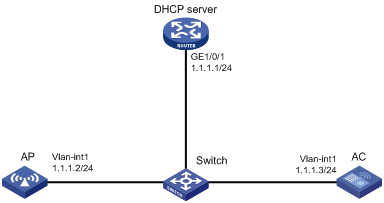
Network requirements
As shown in Figure 3, configure the AP to obtain its IP address and AC IP address from the DHCP server through DHCP Option 43. The AP uses the IP address of the AC to establish a CAPWAP tunnel with the AC.
Configuration procedures
1. Configure the DHCP server:
# Enable the DHCP service.
[DHCP server] dhcp enable
# Configure DHCP address pool 1.
[DHCP server] dhcp server ip-pool 1
[DHCP server-dhcp-pool-1] network 1.1.1.0 mask 255.255.255.0
# Configure Option 43 to specify the IP address of the AC in address pool 0. The right-most bytes 01010103 (1.1.1.3) represents the IP address of the AC.
[DHCP server-dhcp-pool-1] option 43 hex 800700000101010103
[DHCP Server-dhcp-pool-1] quit
[DHCP Server] quit
2. Configure the AC:
# Set the IP address of VLAN-interface 1 on the AC to 1.1.1.3/24.
[AC] interface vlan-interface 1
[AC-Vlan-interface1] ip address 1.1.1.3 24
[AC-Vlan-interface1] quit
# Create AP ap1 with model WA4320i-ACN, and set its serial ID to 210235A1BSC123000050.
[AC] wlan ap ap1 model WA4320i-ACN
[AC-wlan-ap-ap1] serial-id 210235A1BSC123000050
[AC-wlan-ap-ap1] quit
# Start up the AP. The AP performs the following operations:
¡ Obtains its IP address 1.1.1.2 from the DHCP server.
¡ Obtains the IP address of the AC through Option 43.
¡ Establishes a CAPWAP tunnel with the AC.
Verifying the configuration
# Verify the following information:
· The AP obtains the IP address of the AC through DHCP.
· The AP and the AC have established a CAPWAP tunnel.
· The AP is in Run state.
[AC] display wlan ap name ap1 verbose
AP ID : 1
AP group name : default-group
State : Run
Backup type : Master
Online time : 0 days 1 hours 25 minutes 12 seconds
System up time : 0 days 2 hours 22 minutes 12 seconds
Model : WA4320i-ACN
Region code : CN
Region code lock : Disable
Serial ID : 219801A0CNC138011454
MAC address : 0AFB-423B-893C
IP address : 192.168.1.50
UDP control port number : 18313
UDP data port number : N/A
H/W version : Ver.C
S/W version : R2206P02
Boot version : 1.01
USB state : N/A
Power Level : N/A
PowerInfo : N/A
Description : wtp1
Priority : 4
Echo interval : 10 seconds
Statistics report interval : 50 seconds
Fragment size (data) : 1500
Fragment size (control) : 1450
MAC type : Local MAC & Split MAC
Tunnel mode : Local Bridging & 802.3 Frame & Native Frame
Discovery type : DHCP
Retransmission count : 3
Retransmission interval : 5 seconds
Firmware upgrade : Enabled
Sent control packets : 1
Received control packets : 1
Echo requests : 147
Lost echo responses : 0
Average echo delay : 3
Last reboot reason : User soft reboot
Latest IP address : 10.1.0.2
Tunnel down reason : Request wait timer expired
Connection count : 1
Backup Ipv4 : Not configured
Backup Ipv6 : Not configured
Tunnel encryption : Disabled
LED mode : Normal
Remote configuration : Enabled
Radio 1:
Basic BSSID : 7848-59f6-3940
Admin state : Up
Radio type : 802.11ac
Antenna type : internal
Client dot11ac-only : Disabled
Client dot11n-only : Disabled
Channel band-width : 20/40/80MHz
Active band-width : 20/40/80MHz
Secondary channel offset : SCB
Short GI for 20MHz : Supported
Short GI for 40MHz : Supported
Short GI for 80MHz : Supported
Short GI for 160MHz : Not supported
A-MSDU : Enabled
A-MPDU : Enabled
LDPC : Not Supported
STBC : Supported
Operational VHT-MCS Set:
Mandatory : Not configured
Supported : NSS1 0,1,2,3,4,5,6,7,8,9
NSS2 0,1,2,3,4,5,6,7,8,9
Multicast : Not configured
Operational HT MCS Set:
Mandatory : Not configured
Supported : 0, 1, 2, 3, 4, 5, 6, 7, 8, 9,
10, 11, 12, 13, 14, 15
Multicast : Not configured
Channel : 44(auto)
Channel usage(%) : 15
Max power : 20 dBm
Operational rate:
Mandatory : 6, 12, 24 Mbps
Multicast : Auto
Supported : 9, 18, 36, 48, 54 Mbps
Disabled : Not configured
Distance : 1 km
ANI : Enabled
Fragmentation threshold : 2346 bytes
Beacon interval : 100 TU
Protection threshold : 2346 bytes
Long retry threshold : 4
Short retry threshold : 7
Maximum rx duration : 2000 ms
Noise Floor : -102 dBm
Smart antenna : Enabled
Smart antenna policy : Auto
Protection mode : rts-cts
Continuous mode : N/A
HT protection mode : No protection
Radio 2:
Basic BSSID : 7848-59f6-3950
Admin state : Down
Radio type : 802.11b
Antenna type : internal
Client dot11n-only : Disabled
Channel band-width : 20MHz
Active band-width : 20MHz
Secondary channel offset : SCN
Short GI for 20MHz : Supported
Short GI for 40MHz : Supported
A-MSDU : Enabled
A-MPDU : Enabled
LDPC : Not Supported
STBC : Supported
Operational HT MCS Set:
Mandatory : Not configured
Supported : 0, 1, 2, 3, 4, 5, 6, 7, 8, 9,
10, 11, 12, 13, 14, 15
Multicast : Not configured
Channel : 5(auto)
Channel usage(%) : 0
Max power : 20 dBm
Preamble type : Short
Operational rate:
Mandatory : 1, 2, 5.5, 11 Mbps
Multicast : Auto
Supported : 6, 9, 12, 18, 24, 36, 48, 54 Mbps
Disabled : Not configured
Distance : 1 km
ANI : Enabled
Fragmentation threshold : 2346 bytes
Beacon interval : 100 TU
Protection threshold : 2346 bytes
Long retry threshold : 4
Short retry threshold : 7
Maximum rx duration : 2000 ms
Noise Floor : 0 dBm
Smart antenna : Enabled
Smart antenna policy : Auto
Protection mode : rts-cts
Continuous mode : N/A
HT protection mode : No protection
CAPWAP tunnel establishment through DHCPv6 configuration example
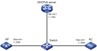
Network requirements
As shown in Figure 4, configure the AP to obtain its IP address and the AC's IP address from the DHCPv6 server through DHCP Option 52. The AP uses the IP address of the AC to establish a CAPWAP tunnel with the AC.
Configuration procedures
1. Configure the DHCPv6 server:
# Assign an IPv6 address to GigabitEthernet 1/0/1.
<DHCPv6 Server> system-view
[DHCPv6 Server] interface gigabitethernet 1/0/1
[DHCPv6 Server-GigabitEthernet1/0/1] ipv6 address 1::1/64
# Disable RA message advertising suppression.
[DHCPv6 Server-GigabitEthernet1/0/1] undo ipv6 nd ra halt
# Set the managed address configuration flag (M) to 1 in RA advertisements to be sent.
[DHCPv6 Server-GigabitEthernet1/0/1] ipv6 nd autoconfig managed-address-flag
# Set the other stateful configuration flag (O) to 1 in RA advertisements to be sent.
[DHCPv6 Server-GigabitEthernet1/0/1] ipv6 nd autoconfig other-flag
# Enable the DHCPv6 service on GigabitEthernet 1/0/1.
[DHCPv6 Server-GigabitEthernet1/0/1] ipv6 dhcp select server
[DHCPv6 Server-GigabitEthernet1/0/1] quit
# Create a DHCPv6 address pool, and specify an IPv6 subnet for dynamic allocation in the DHCPv6 address pool.
[DHCPv6 Server] ipv6 dhcp pool 1
[DHCPv6 Server-dhcp6-pool-1] network 1::0/64
[DHCPv6 Server-dhcp6-pool-1] quit
# Configure Option 52 that specifies an AC address 1::3 in DHCPv6 address pool 1.
[DHCPv6 Server-dhcp-pool-1] option 52 hex 00010000000000000000000000000003
[DHCPv6 Server-dhcp-pool-1] quit
[DHCPv6 Server] quit
2. Configure the AC:
# Set the IPv6 address of VLAN-interface 1 to 1::3/64.
<AC> system-view
[AC] interface vlan-interface 1
[AC-Vlan-interface1] ipv6 address 1::3 64
# Create an AP named ap1 and specify its model and serial ID.
[AC] wlan ap ap1 model WA4320i-ACN
[AC-wlan-ap-ap1] serial-id 210235A1BSC123000050
[AC-wlan-ap-ap1] quit
# Start up the AP. The AP performs the following operations:
¡ Obtains its IPv6 address 1::2 from the DHCP server.
¡ Obtains the IPv6 address of the AC through Option 52.
¡ Establishes a CAPWAP tunnel with the AC.
Verifying the configuration
# Verify the following information:
· The AP obtains the IP address of the AC through DHCP.
· The AP and the AC have established a CAPWAP tunnel.
· The AP is in Run state.
[AC] display wlan ap name ap1 verbose
AP name : ap1
AP ID : 1
AP group name : default-group
State : Run
Backup type : Master
Online time : 0 days 1 hours 25 minutes 12 seconds
System up time : 0 days 2 hours 22 minutes 12 seconds
Model : WA4320i-ACN
Region code : CN
Region code lock : Disable
Serial ID : 219801A0CNC138011454
MAC address : 0AFB-423B-893C
IP address : 1::2
UDP control port number : 18313
UDP data port number : N/A
H/W version : Ver.C
S/W version : R2206P02
Boot version : 1.01
USB state : N/A
Power Level : N/A
PowerInfo : N/A
Description : wtp1
Priority : 4
Echo interval : 10 seconds
Statistics report interval : 50 seconds
Fragment size (data) : 1500
Fragment size (control) : 1450
MAC type : Local MAC & Split MAC
Tunnel mode : Local Bridging & 802.3 Frame & Native Frame
Discovery type : DHCP
Retransmission count : 3
Retransmission interval : 5 seconds
Firmware upgrade : Enabled
Sent control packets : 1
Received control packets : 1
Echo requests : 147
Lost echo responses : 0
Average echo delay : 3
Last reboot reason : User soft reboot
Latest IP address : 10.1.0.2
Tunnel down reason : Request wait timer expired
Connection count : 1
Backup Ipv4 : Not configured
Backup Ipv6 : Not configured
Tunnel encryption : Disabled
LED mode : Normal
Remote configuration : Enabled
Radio 1:
Basic BSSID : 7848-59f6-3940
Admin state : Up
Radio type : 802.11ac
Antenna type : internal
Client dot11ac-only : Disabled
Client dot11n-only : Disabled
Channel band-width : 20/40/80MHz
Active band-width : 20/40/80MHz
Secondary channel offset : SCB
Short GI for 20MHz : Supported
Short GI for 40MHz : Supported
Short GI for 80MHz : Supported
Short GI for 160MHz : Not supported
A-MSDU : Enabled
A-MPDU : Enabled
LDPC : Not Supported
STBC : Supported
Operational VHT-MCS Set:
Mandatory : Not configured
Supported : NSS1 0,1,2,3,4,5,6,7,8,9
NSS2 0,1,2,3,4,5,6,7,8,9
Multicast : Not configured
Operational HT MCS Set:
Mandatory : Not configured
Supported : 0, 1, 2, 3, 4, 5, 6, 7, 8, 9,
10, 11, 12, 13, 14, 15
Multicast : Not configured
Channel : 44(auto)
Channel usage(%) : 15
Max power : 20 dBm
Operational rate:
Mandatory : 6, 12, 24 Mbps
Multicast : Auto
Supported : 9, 18, 36, 48, 54 Mbps
Disabled : Not configured
Distance : 1 km
ANI : Enabled
Fragmentation threshold : 2346 bytes
Beacon interval : 100 TU
Protection threshold : 2346 bytes
Long retry threshold : 4
Short retry threshold : 7
Maximum rx duration : 2000 ms
Noise Floor : -102 dBm
Smart antenna : Enabled
Smart antenna policy : Auto
Protection mode : rts-cts
Continuous mode : N/A
HT protection mode : No protection
Radio 2:
Basic BSSID : 7848-59f6-3950
Admin state : Down
Radio type : 802.11b
Antenna type : internal
Client dot11n-only : Disabled
Channel band-width : 20MHz
Active band-width : 20MHz
Secondary channel offset : SCN
Short GI for 20MHz : Supported
Short GI for 40MHz : Supported
A-MSDU : Enabled
A-MPDU : Enabled
LDPC : Not Supported
STBC : Supported
Operational HT MCS Set:
Mandatory : Not configured
Supported : 0, 1, 2, 3, 4, 5, 6, 7, 8, 9,
10, 11, 12, 13, 14, 15
Multicast : Not configured
Channel : 5(auto)
Channel usage(%) : 0
Max power : 20 dBm
Preamble type : Short
Operational rate:
Mandatory : 1, 2, 5.5, 11 Mbps
Multicast : Auto
Supported : 6, 9, 12, 18, 24, 36, 48, 54 Mbps
Disabled : Not configured
Distance : 1 km
ANI : Enabled
Fragmentation threshold : 2346 bytes
Beacon interval : 100 TU
Protection threshold : 2346 bytes
Long retry threshold : 4
Short retry threshold : 7
Maximum rx duration : 2000 ms
Noise Floor : 0 dBm
Smart antenna : Enabled
Smart antenna policy : Auto
Protection mode : rts-cts
Continuous mode : N/A
HT protection mode : No protection
CAPWAP tunnel establishment through DNS configuration example
Network requirements
As shown in Figure 5, configure the AP to obtain the IP address of the AC through DNS to establish a CAPWAP tunnel with the AC.
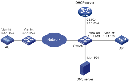
Configuration procedures
1. Configure the DHCP server:
# Enable the DHCP service, configure DHCP address pool 1, and set the domain name suffix of the AC to abc.
[DHCP server] dhcp enable
[DHCP server] dhcp server ip-pool 1
[DHCP server-dhcp-pool-1] network 1.1.1.0 mask 255.255.255.0
[DHCP server-dhcp-pool-1] domain-name abc
[DHCP server-dhcp-pool-1] dns-list 1.1.1.4
[DHCP server-dhcp-pool-1] gateway-list 1.1.1.2
[DHCP server-dhcp-pool-1] quit
[DHCP server] quit
2. Configure a mapping between domain name h3c.abc and IP address 2.1.1.1/24. For more information, see Layer 3—IP Services Configuration Guide. (Details not shown.)
3. Configure the AC:
# Set the IP address of VLAN-interface 1 to 2.1.1.1/24.
[AC] interface vlan-interface 1
[AC-Vlan-interface1] ip address 2.1.1.1 24
[AC-Vlan-interface1] quit
# Configure a default route with next hop address 2.1.1.2.
[AC] ip route-static 0.0.0.0 0 2.1.1.2
# Create AP ap1 and specify its model and serial ID.
[AC] wlan ap ap1 model WA4320i-ACN
[AC-wlan-ap-ap1] serial-id 210235A1BSC123000050
# Start up the AP.
[AC-wlan-ap-ap1] quit
The AP performs the following operations:
¡ Obtains its IP address 1.1.1.1, the domain name suffix of the AC, and the IP address of the DNS server from the DHCP server.
¡ Adds the domain name suffix to the hostname.
¡ Informs the DNS client to translate the domain name into an IP address.
¡ Uses the IP address of the AC to establish a CAPWAP tunnel with the AC.
Verifying the configuration
# Verify the following information:
· The AP and the AC have established a CAPWAP tunnel.
· The AP is in Run state.
· The AP obtains the IP address of the AC through DNS.
[AC] display wlan ap name ap1 verbose
AP name : ap1
AP ID : 1
AP group name : default-group
State : Run
Backup type : Master
Online time : 0 days 1 hours 25 minutes 12 seconds
System up time : 0 days 2 hours 22 minutes 12 seconds
Model : WA4320i-ACN
Region code : CN
Region code lock : Disable
Serial ID : 210235A1BSC123000050
MAC address : 0AFB-423B-893C
IP address : 1.1.1.1
UDP control port number : 18313
UDP data port number : N/A
H/W version : Ver.C
S/W version : R2206P02
Boot version : 1.01
USB state : N/A
Power Level : N/A
PowerInfo : N/A
Description : wtp1
Priority : 4
Echo interval : 10 seconds
Statistics report interval : 50 seconds
Fragment size (data) : 1500
Fragment size (control) : 1450
MAC type : Local MAC & Split MAC
Tunnel mode : Local Bridging & 802.3 Frame & Native Frame
Discovery type : DNS
Retransmission count : 3
Retransmission interval : 5 seconds
Firmware upgrade : Enabled
Sent control packets : 1
Received control packets : 1
Echo requests : 147
Lost echo responses : 0
Average echo delay : 3
Last reboot reason : User soft reboot
Latest IP address : 10.1.0.2
Tunnel down reason : Request wait timer expired
Connection count : 1
Backup Ipv4 : Not configured
Backup Ipv6 : Not configured
Tunnel encryption : Disabled
LED mode : Normal
Remote configuration : Enabled
Radio 1:
Basic BSSID : 7848-59f6-3940
Admin state : Up
Radio type : 802.11ac
Antenna type : internal
Client dot11ac-only : Disabled
Client dot11n-only : Disabled
Channel band-width : 20/40/80MHz
Active band-width : 20/40/80MHz
Secondary channel offset : SCB
Short GI for 20MHz : Supported
Short GI for 40MHz : Supported
Short GI for 80MHz : Supported
Short GI for 160MHz : Not supported
A-MSDU : Enabled
A-MPDU : Enabled
LDPC : Not Supported
STBC : Supported
Operational VHT-MCS Set:
Mandatory : Not configured
Supported : NSS1 0,1,2,3,4,5,6,7,8,9
NSS2 0,1,2,3,4,5,6,7,8,9
Multicast : Not configured
Operational HT MCS Set:
Mandatory : Not configured
Supported : 0, 1, 2, 3, 4, 5, 6, 7, 8, 9,
10, 11, 12, 13, 14, 15
Multicast : Not configured
Channel : 44(auto)
Channel usage(%) : 15
Max power : 20 dBm
Operational rate:
Mandatory : 6, 12, 24 Mbps
Multicast : Auto
Supported : 9, 18, 36, 48, 54 Mbps
Disabled : Not configured
Distance : 1 km
ANI : Enabled
Fragmentation threshold : 2346 bytes
Beacon interval : 100 TU
Protection threshold : 2346 bytes
Long retry threshold : 4
Short retry threshold : 7
Maximum rx duration : 2000 ms
Noise Floor : -102 dBm
Smart antenna : Enabled
Smart antenna policy : Auto
Protection mode : rts-cts
Continuous mode : N/A
HT protection mode : No protection
Radio 2:
Basic BSSID : 7848-59f6-3950
Admin state : Down
Radio type : 802.11b
Antenna type : internal
Client dot11n-only : Disabled
Channel band-width : 20MHz
Active band-width : 20MHz
Secondary channel offset : SCN
Short GI for 20MHz : Supported
Short GI for 40MHz : Supported
A-MSDU : Enabled
A-MPDU : Enabled
LDPC : Not Supported
STBC : Supported
Operational HT MCS Set:
Mandatory : Not configured
Supported : 0, 1, 2, 3, 4, 5, 6, 7, 8, 9,
10, 11, 12, 13, 14, 15
Multicast : Not configured
Channel : 5(auto)
Channel usage(%) : 0
Max power : 20 dBm
Preamble type : Short
Operational rate:
Mandatory : 1, 2, 5.5, 11 Mbps
Multicast : Auto
Supported : 6, 9, 12, 18, 24, 36, 48, 54 Mbps
Disabled : Not configured
Distance : 1 km
ANI : Enabled
Fragmentation threshold : 2346 bytes
Beacon interval : 100 TU
Protection threshold : 2346 bytes
Long retry threshold : 4
Short retry threshold : 7
Maximum rx duration : 2000 ms
Noise Floor : 0 dBm
Smart antenna : Enabled
Smart antenna policy : Auto
Protection mode : rts-cts
Continuous mode : N/A
HT protection mode : No protection
Auto AP configuration example
Network requirements
As shown in Figure 6, enable the auto AP feature on the AC. The AP obtains the AC IP address through DHCP Option 43 and establishes a CAPWAP tunnel with the AC.
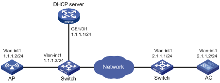
Configuration procedures
1. Configure the DHCP server:
# Enable the DHCP service.
<DHCP server> system-view
[DHCP server] dhcp enable
# Configure DHCP address pool 1.
[DHCP server] dhcp server ip-pool 1
[DHCP server-dhcp-pool-1] network 1.1.1.0 mask 255.255.255.0
# Configure Option 43 to specify the IP address of the AC in address pool 0. The right-most bytes 02010102 (2.1.1.2) represents the IP address of the AC.
[DHCP server-dhcp-pool-1] option 43 ip-address hex 800700000102010102
[DHCP Server-dhcp-pool-1] gateway-list 1.1.1.3
[DHCP Server-dhcp-pool-1] quit
[DHCP Server] quit
2. Configure the AC:
# Set the IP address of VLAN-interface 1 on the AC to 2.1.1.2/24.
[AC] interface vlan-interface 1
[AC-Vlan-interface1] ip address 2.1.1.2 24
[AC-Vlan-interface1] quit
# Configure a default route with next hop 2.1.1.1.
[AC] ip route-static 0.0.0.0 0 2.1.1.1
# Enable auto AP.
[AC] wlan auto-ap enable
Verifying the configuration
# Verify that the AP has established a CAPWAP tunnel with the AC.
[AC] display wlan ap name 0011-2200-0101 verbose
AP name : 0011-2200-0101
AP ID : 1
AP group name : default-group
State : Run
Backup type : Master
Online time : 0 days 1 hours 25 minutes 12 seconds
System up time : 0 days 2 hours 22 minutes 12 seconds
Model : WA4320i-ACN
Region code : CN
Region code lock : Disable
Serial ID : 219801A0CNC138011454
MAC address : 0011-2200-0101
IP address : 1.1.1.2
UDP control port number : 18313
UDP data port number : N/A
H/W version : Ver.C
S/W version : R2206P02
Boot version : 1.01
USB state : N/A
Power Level : N/A
PowerInfo : N/A
Description : wtp1
Priority : 4
Echo interval : 10 seconds
Statistics report interval : 50 seconds
Fragment size (data) : 1500
Fragment size (control) : 1450
MAC type : Local MAC & Split MAC
Tunnel mode : Local Bridging & 802.3 Frame & Native Frame
Discovery type : DHCP
Retransmission count : 3
Retransmission interval : 5 seconds
Firmware upgrade : Enabled
Sent control packets : 1
Received control packets : 1
Echo requests : 147
Lost echo responses : 0
Average echo delay : 3
Last reboot reason : User soft reboot
Latest IP address : 10.1.0.2
Tunnel down reason : Request wait timer expired
Connection count : 1
Backup Ipv4 : Not configured
Backup Ipv6 : Not configured
Tunnel encryption : Disabled
LED mode : Normal
Remote configuration : Enabled
Radio 1:
Basic BSSID : 7848-59f6-3940
Admin state : Up
Radio type : 802.11ac
Antenna type : internal
Client dot11ac-only : Disabled
Client dot11n-only : Disabled
Channel band-width : 20/40/80MHz
Active band-width : 20/40/80MHz
Secondary channel offset : SCB
Short GI for 20MHz : Supported
Short GI for 40MHz : Supported
Short GI for 80MHz : Supported
Short GI for 160MHz : Not supported
A-MSDU : Enabled
A-MPDU : Enabled
LDPC : Not Supported
STBC : Supported
Operational VHT-MCS Set:
Mandatory : Not configured
Supported : NSS1 0,1,2,3,4,5,6,7,8,9
NSS2 0,1,2,3,4,5,6,7,8,9
Multicast : Not configured
Operational HT MCS Set:
Mandatory : Not configured
Supported : 0, 1, 2, 3, 4, 5, 6, 7, 8, 9,
10, 11, 12, 13, 14, 15
Multicast : Not configured
Channel : 44(auto)
Channel usage(%) : 15
Max power : 20 dBm
Operational rate:
Mandatory : 6, 12, 24 Mbps
Multicast : Auto
Supported : 9, 18, 36, 48, 54 Mbps
Disabled : Not configured
Distance : 1 km
ANI : Enabled
Fragmentation threshold : 2346 bytes
Beacon interval : 100 TU
Protection threshold : 2346 bytes
Long retry threshold : 4
Short retry threshold : 7
Maximum rx duration : 2000 ms
Noise Floor : -102 dBm
Smart antenna : Enabled
Smart antenna policy : Auto
Protection mode : rts-cts
Continuous mode : N/A
HT protection mode : No protection
Radio 2:
Basic BSSID : 7848-59f6-3950
Admin state : Down
Radio type : 802.11b
Antenna type : internal
Client dot11n-only : Disabled
Channel band-width : 20MHz
Active band-width : 20MHz
Secondary channel offset : SCN
Short GI for 20MHz : Supported
Short GI for 40MHz : Supported
A-MSDU : Enabled
A-MPDU : Enabled
LDPC : Not Supported
STBC : Supported
Operational HT MCS Set:
Mandatory : Not configured
Supported : 0, 1, 2, 3, 4, 5, 6, 7, 8, 9,
10, 11, 12, 13, 14, 15
Multicast : Not configured
Channel : 5(auto)
Channel usage(%) : 0
Max power : 20 dBm
Preamble type : Short
Operational rate:
Mandatory : 1, 2, 5.5, 11 Mbps
Multicast : Auto
Supported : 6, 9, 12, 18, 24, 36, 48, 54 Mbps
Disabled : Not configured
Distance : 1 km
ANI : Enabled
Fragmentation threshold : 2346 bytes
Beacon interval : 100 TU
Protection threshold : 2346 bytes
Long retry threshold : 4
Short retry threshold : 7
Maximum rx duration : 2000 ms
Noise Floor : 0 dBm
Smart antenna : Enabled
Smart antenna policy : Auto
Protection mode : rts-cts
Continuous mode : N/A
HT protection mode : No protection
AP group configuration example
Network requirements
As shown in Figure 7, configure AP groups and add AP 1 to AP group group1, and AP 2, AP 3, and AP 4 to AP group group2.
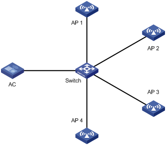
Configuration procedure
1. Configure APs to obtain their IP addresses and the AC IP address from the DHCP server. (Details not shown.)
2. Configure manual APs. (Details not shown.)
3. Configure AP groups:
# Create AP group group1.
[AC] wlan ap-group group1
# Add AP 1 to AP group group1.
[AC-wlan-ap-group-group1] ap ap1
[AC-wlan-ap-group-group1] quit
# Create AP group group2.
# Add AP 2, AP 3, and AP 4 to AP group group2.
[AC-wlan-ap-group-group2] ap ap2 ap3 ap4
[AC-wlan-ap-group-group2] quit
[AC] quit
Verifying the configuration
# Verify that AP 1 is in AP group group1, and AP 2, AP 3, and AP 4 are in AP group group2.
[AC-wlan-ap-group-group2] display wlan ap-group
Total number of AP groups: 3
AP group name : default-group
Description : Not configured
AP model : Not configured
APs : Not configured
AP group name : group1
Description : Not configured
AP model : WA4320i-ACN
AP grouping rules:
AP name : ap1
Serial ID : Not configured
MAC address : Not configured
IPv4 address : Not configured
IPv6 address : Not configured
APs : ap1 (AP name)
AP group name : group2
Description : Not configured
AP model : WA4320i-ACN
AP grouping rules:
AP name : ap2, ap3, ap4
Serial ID : Not configured
MAC address : Not configured
IPv4 address : Not configured
IPv6 address : Not configured
APs : ap2 (AP name), ap3 (AP name), ap4 (AP name)