- Table of Contents
-
- 02-WLAN
- 00-Preface
- 01-AP management configuration
- 02-Radio management configuration
- 03-WLAN access configuration
- 04-WLAN security configuration
- 05-WLAN authentication configuration
- 06-WIPS configuration
- 07-WLAN QoS configuration
- 08-WLAN roaming configuration
- 09-WLAN load balancing configuration
- 10-WLAN radio resource measurement configuration
- 11-Channel scanning configuration
- 12-Band navigation configuration
- 13-WLAN high availability configuration
- 14-802.11r configuration
- 15-Wireless location configuration
- 16-Hotspot 2.0 configuration
- 17-WLAN RRM configuration
- 18-WT configuration
- 19-IoT AP configuration
- 20-CM tunnel configuration
- 21-Cloud connection configuration
- 22-WLAN IP snooping configuration
- 23-WLAN fast forwarding configuration
- Related Documents
-
| Title | Size | Download |
|---|---|---|
| 03-WLAN access configuration | 338.95 KB |
Whitelist- and blacklist-based access control
Configuration restrictions and guidelines
Configuring a service template
Configuring a description for a service template
Specifying the VLAN allocation method for clients
Configuring clients to prefer the authorization VLAN after roaming
Setting the client cache aging time
Enabling client association at the AC or APs
Specifying the client traffic forwarder
Enabling client traffic forwarding
Setting the encapsulation format for client data frames
Binding a service template to a radio
Binding a service template to a radio in radio view
Binding a service template to a radio in AP group radio view
Specifying a region code in AP view
Specifying a region code in AP group view
Specifying a global region code
Disabling an AP from responding to broadcast probe requests
Disabling an AP from responding to broadcast probe requests in AP view
Disabling APs in an AP group from responding to broadcast probe requests in AP group view
Setting the client idle timeout timer
Setting the client idle timeout timer in AP view
Setting the client idle timeout timer in AP group view
Configuring client keepalive in AP view
Configuring client keepalive in AP group view
Configuring an AP to not inherit the specified service template from an AP group
Setting the NAS ID in AP group view
Setting the way in which an AP processes traffic from unknown clients
Configuring policy-based forwarding
Configuring a forwarding policy
Applying a forwarding policy to a service template
Applying a forwarding policy to a user profile
Specifying a permitted AP group for client access
Specifying a permitted SSID for client access
Adding a client to the whitelist
Adding a client to the static blacklist
Configuring the dynamic blacklist
Setting the idle period before client reauthentication
Deploying a configuration file to an AP
Deploying a configuration file to an AP in AP view
Deploying a configuration file to an AP in AP group AP model view
Configuring uplink client rate limit
Specifying the Web server to which client information is reported
Enabling the device to generate client logs in the specified format
Displaying and maintaining WLAN access
WLAN access configuration examples
WLAN access configuration example
Whitelist configuration example
Static blacklist configuration example
Configuring WLAN access
This chapter describes how to configure WLAN access.
WLAN access overview
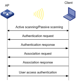
A wireless client can access a WLAN only when it completes the scanning, link layer authentication, association, and WLAN authentication processes.
For more information about data link layer authentication, see "Configuring WLAN security."
For more information about WLAN authentication, see "Configuring WLAN authentication."
Figure 1 WLAN access process
Scanning
Active scanning
A wireless client periodically scans surrounding wireless networks by sending probe requests. It obtains network information from received probe responses. Based on whether a probe request carries an SSID, active scanning can be divided into the following types:
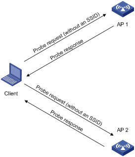
· Active scanning of all wireless networks.
As shown in Figure 2, the client periodically sends a probe request on each of its supported channels to scan wireless networks. APs that receive the probe request send a probe response, which carries the available wireless network information. The client associates with the optimal AP.
Figure 2 Scanning all wireless networks
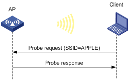
· Active scanning of a specific wireless network.
As shown in Figure 3, the client periodically sends a probe request carrying the specified SSID if the wireless client has an SSID configured or has been associated with an SSID. When an AP that can provide wireless services with the specified SSID receives the probe request, it sends a probe response.
Figure 3 Scanning a specific wireless network
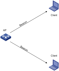
Passive scanning
As shown in Figure 4, the clients periodically listen to beacon frames sent by APs on their supported channels to get information about surrounding wireless networks. Then the clients select an AP for association. Passive scanning is used when clients want to save power.
Association
A client sends an association request to the associated AP after passing date link layer authentication. Upon receiving the request, the AP determines the capability supported by the wireless client and sends an association response to the client. Then the client is associated with the AP.
Client access control
The following client access control methods are available:
· AP group-based access control—Allows clients associated with APs in the specified AP group to access the WLAN.
· SSID-based access control—Allows clients associated with the specified SSID to access the WLAN.
· Whitelist- and blacklist-based access control—Uses the whitelist and blacklists to control access for the specified clients.
AP group-based access control
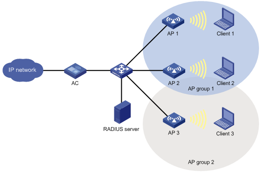
As shown in Figure 5, for AP group-based access control, configure AP group 1 as the permitted AP group for Client 1 and Client 2, and configure AP group 2 as the permitted AP group for Client 3.
When a client passes authentication, the server sends the related user profile to the AC. The AC examines whether the AP with which the client associates is in the permitted AP group. If it is, the client is allowed to access the WLAN. If it is not, the AC logs off the client.
Figure 5 AP group-based access control
SSID-based access control
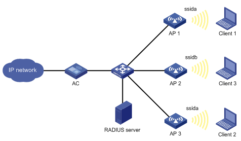
As shown in Figure 6, for SSID-based access control, configure ssida as the permitted SSID for Client 1 and Client 2, and configure ssidb as the permitted SSID for Client 3.
When a client passes authentication, the server sends the related user profile to the AC. The AC examines whether the associated SSID of the client is the permitted SSID. If it is, the client is allowed to access the WLAN. If it is not, the AC logs off the client.
Figure 6 AP group-based access control
Whitelist- and blacklist-based access control
You can configure the whitelist or blacklists to filter frames from WLAN clients and implement client access control.
· Whitelist—Contains the MAC addresses of all clients allowed to access the WLAN. Frames from clients not in the whitelist are discarded. This list is manually configured.
· Static blacklist—Contains the MAC addresses of clients forbidden to access the WLAN. This list is manually configured.
· Dynamic blacklist—Contains the MAC addresses of clients forbidden to access the WLAN. An AP adds the MAC address of a client forbidden to access the WLAN to the list when WIPS is configured or when URL redirection is enabled for WLAN MAC authentication clients. The entries in the list are removed when the aging timer expires. For more information about WIPS, see "Configuring WIPS". For more information about WLAN MAC authentication, see "Configuring WLAN authentication."
When an AP receives an association request and sends an Add Mobile message to the AC, the AC performs the following operations to determine whether to permit the client:
1. Searches the whitelist.
¡ If the client MAC address does not match any entries in the whitelist, the client is rejected.
¡ If a match is found, the client is permitted.
2. Searches the static and dynamic blacklists if no whitelist entries exist.
¡ If the client MAC address matches an entry in either blacklist, the client is rejected.
¡ If no match is found, or no blacklist entries exist, the client is permitted.
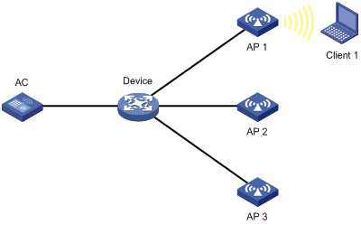
Figure 7 Whitelist- and blacklist-based access control
Configuration restrictions and guidelines
The priorities for the configuration in AP view, AP group view, and global configuration view are in descending order.
Configuration task list
Configuring a service template
A service template defines a set of wireless service attributes, such as SSID and authentication method.
To configure a service template:
|
Command |
Remarks |
|
|
1. Enter system view. |
N/A |
|
|
2. Create a service template. |
By default, no service template exists. |
|
|
3. Assign clients coming online through the service template to a VLAN. |
By default, clients are assigned to VLAN 1 after coming online through a service template. |
Setting an SSID
APs advertise SSIDs in beacon frames. If the number of clients in a BSS exceeds the limit or the BSS is unavailable, you can enable SSID-hidden to prevent clients from discovering the BSS. When SSID-hidden is enabled, the BSS hides its SSID in beacon frames and does not respond to broadcast probe requests. A client must send probe requests with the specified SSID to access the WLAN. This feature can protect the WLAN from being attacked.
To set an SSID:
|
Command |
Remarks |
|
|
1. Enter system view. |
N/A |
|
|
2. Enter service template view. |
N/A |
|
|
3. Set an SSID for the service template. |
By default, no SSID is set for a service template. As a best practice, set a unique SSID for a service template. |
|
|
4. (Optional.) Enable SSID-hidden in beacon frames. |
By default, beacon frames carry SSIDs. |
Configuring a description for a service template
|
Step |
Command |
Remarks |
|
1. Enter system view. |
system-view |
N/A |
|
2. Enter service template view. |
wlan service-template service-template-name |
N/A |
|
3. Configure a description for the service template. |
description text |
By default, a service template does not have a description. |
Specifying the VLAN allocation method for clients
When a client comes online for the first time, the radio assigns a random VLAN to it. When the client comes online again, the VLAN assigned to the client depends on the allocation method.
· Static allocation—The client inherits the VLAN that has been assigned to it. If the IP address lease has not expired, the client will use the same IP address. This method helps save IP addresses.
· Dynamic allocation—The client is re-assigned a VLAN. This method balances clients in all VLANs.
· Compatible static allocation—The client inherits the VLAN that has been assigned to it when roaming between Comware 5 and Comware 7 ACs.
To specify the VLAN allocation method for clients:
|
Step |
Command |
Remarks |
|
1. Enter system view. |
system-view |
N/A |
|
2. Enter service template view. |
wlan service-template service-template-name |
N/A |
|
3. Specify the VLAN allocation method for clients. |
client vlan-alloc { dynamic | static | static-compatible } |
By default, the VLAN allocation method for clients is dynamic. |
Configuring clients to prefer the authorization VLAN after roaming
As a best practice, configure this feature on all ACs in a mobility group.
Typically, the VLAN of a client remains unchanged after client roaming. However, if the client triggers a security alert configured on IMC after roams to another AP, the issued authorization VLAN for user isolation takes effect.
This feature takes effect only on 802.1X and MAC authentication clients.
To configure clients to prefer the authorization VLAN after roaming:
|
Step |
Command |
Remarks |
|
1. Enter system view. |
system-view |
N/A |
|
2. Enter service template view. |
wlan service-template service-template-name |
N/A |
|
3. Configure clients to prefer the authorization VLAN after roaming. |
client preferred-vlan authorized |
By default, clients prefer the authorization VLAN after roaming. |
Setting the client cache aging time
The client cache saves information such as the PMK list and access VLAN for clients. If a client roams to another AP before the cache aging time expires, the client can inherit the cache information. If a client does not come online before the cache aging time expires, its cache information is cleared.
To set the client cache aging time:
|
Step |
Command |
Remarks |
|
1. Enter system view. |
system-view |
N/A |
|
2. Enter service template view. |
wlan service-template service-template-name |
N/A |
|
3. Set the client cache aging time. |
client cache aging-time aging-time |
By default, the client cache aging time is 180 seconds. |
Enabling client association at the AC or APs
If you enable client association at the AC, management frames are sent to the AC over the CAPWAP tunnel. This ensures security and facilitates management. As a best practice, enable client association at the APs when the network between AC and AP is complicated.
Layer 3 roaming is not supported if client association is enabled at APs. When you use the service-template command, you must specify the same VLAN for the APs that use the same service template and have overlapping coverage areas.
To enable client association at the AC or APs:
|
Step |
Command |
Remarks |
|
1. Enter system view. |
system-view |
N/A |
|
2. Enter service template view. |
wlan service-template service-template-name |
N/A |
|
3. Enable client association at the AC or APs. |
client association-location { ac | ap } |
By default, client association is performed at the AC. |
Specifying the client traffic forwarder
The client traffic forwarder can be the AC (centralized forwarding) or APs (local forwarding). Using APs to forward client traffic releases the forwarding burden on the AC.
If APs forward client traffic, you can specify a VLAN or a VLAN range for the APs to forward traffic from the specified VLANs. The AC forwards data traffic from the other VLANs.
For the configuration of using the AC to forward client traffic to take effect, make sure client traffic forwarding has been enabled.
To specify the client traffic forwarder:
|
Step |
Command |
Remarks |
|
1. Enter system view. |
system-view |
N/A |
|
2. Enter service template view. |
wlan service-template service-template-name |
N/A |
|
3. Specify the client traffic forwarder. |
client forwarding-location { ac | ap [ vlan { vlan-start [ to vlan-end ] } ] } |
By default, the default setting for this command varies by device model. |
Enabling client traffic forwarding
You must enable this feature if you configure the AC as the client traffic forwarder.
To enable client traffic forwarding:
|
Step |
Command |
Remarks |
|
1. Enter system view. |
system-view |
N/A |
|
2. Enable client traffic forwarding. |
wlan client forwarding enable |
By default, client traffic forwarding is enabled. |
Setting the encapsulation format for client data frames
In the centralized forwarding infrastructure, an AP sends data frames from clients to the AC over the CAPWAP tunnel. You can set the encapsulation format for the client data frames to 802.3 or 802.11. As a best practice, set the format to 802.3 so the AC does not need to perform frame format conversion.
To set the encapsulation format for client data frames:
|
Step |
Command |
Remarks |
|
1. Enter system view. |
system-view |
N/A |
|
2. Enter service template view. |
wlan service-template service-template-name |
N/A |
|
3. Set the encapsulation format for client data frames. |
client frame-format { dot3 | dot11 } |
By default, client data frames are encapsulated in the 802.3 format. |
Enabling quick association
Enabling load balancing or band navigation might affect client association efficiency. For delay-sensitive services or in an environment where load balancing and band navigation is not needed, you can enable quick association for a service template.
This feature disables the device from performing load balancing or band navigation on clients associated with the service template even if load balancing and band navigation is enabled in the WLAN.
To enable quick association:
|
Step |
Command |
Remarks |
|
1. Enter system view. |
system-view |
N/A |
|
2. Enter service template view. |
wlan service-template service-template-name |
N/A |
|
3. Enable quick association. |
By default, quick association is disabled. |
Enabling a service template
|
Command |
Remarks |
|
|
1. Enter system view. |
N/A |
|
|
2. Enter service template view. |
N/A |
|
|
3. Enable the service template. |
By default, a service template is disabled. |
Binding a service template to a radio
If you bind a service template to a radio, the AP creates a BSS that can provide wireless services defined in the service template.
You can perform the following tasks when binding a service template to a radio:
· Bind a VLAN group to the radio so that clients associated with the BSS will be assigned evenly to all VLANs in the VLAN group.
· Bind the NAS port ID or the NAS ID to the radio to identify the network access server.
· Enable the AP to hide SSIDs in beacon frames.
Binding a service template to a radio in radio view
|
Command |
Remarks |
|
|
1. Enter system view. |
N/A |
|
|
2. Enter AP view. |
N/A |
|
|
3. Enter radio view. |
N/A |
|
|
4. Bind a service template to the radio. |
service-template service-template-name [ vlan vlan-id | vlan-group vlan-group-name ] [ ssid-hide ] [ nas-id nas-id | nas-port-id nas-port-id ] |
By default, the configuration in AP group view is used. You can bind a maximum of 16 service templates to a radio. |
Binding a service template to a radio in AP group radio view
|
Step |
Command |
Remarks |
|
1. Enter system view. |
system-view |
N/A |
|
2. Enter AP group view. |
wlan ap-group group-name |
N/A |
|
3. Enter AP model view. |
ap-model ap-model |
N/A |
|
4. Enter radio view. |
radio radio-id |
N/A |
|
5. Bind a service template to the radio. |
service-template service-template-name [ vlan vlan-id | vlan-group vlan-group-name ] [ ssid-hide ] [ nas-id nas-id | nas-port-id nas-port-id ] |
By default, a radio is not bound to any service templates. You can bind a maximum of 16 service templates to a radio. |
Specifying a region code
A region code determines characteristics such as available frequencies, available channels, and transmit power level. Set a valid region code before configuring an AP.
To prevent regulation violation caused by region code modification, lock the region code.
Specifying a region code in AP view
|
Step |
Command |
Remarks |
|
1. Enter system view. |
system-view |
N/A |
|
2. Enter AP view. |
N/A |
|
|
3. Specify a region code. |
By default, the AP uses the configuration in AP group view. If no region code exists in AP group view, the AP uses the configuration in global configuration view. |
|
|
4. Lock the region code. |
By default, the AP uses the configuration in AP group view. If no configuration exists in AP group view, the AP uses the configuration in global configuration view. |
Specifying a region code in AP group view
|
Step |
Command |
Remarks |
|
1. Enter system view. |
system-view |
N/A |
|
2. Enter AP group view. |
N/A |
|
|
3. Specify a region code. |
region-code code |
By default, the AP group uses the configuration in global configuration view. |
|
4. Lock the region code. |
region-code-lock enable |
By default, the AP group uses the configuration in global configuration view. |
Specifying a global region code
|
Step |
Command |
Remarks |
|
1. Enter system view. |
system-view |
N/A |
|
2. Enter global configuration view. |
N/A |
|
|
3. Specify a region code. |
region-code code |
By default, the region code is CN. |
|
4. Lock the region code. |
region-code-lock enable |
By default, the region code is not locked. |
Disabling an AP from responding to broadcast probe requests
Broadcast probe requests do not carry any SSIDs. Upon receiving a broadcast probe request, an AP responds with a probe response that carries service information for the AP.
This feature enables clients that send unicast probe requests to the AP to associate with the AP more easily.
Disabling an AP from responding to broadcast probe requests in AP view
|
Step |
Command |
Remarks |
|
1. Enter system view. |
system-view |
N/A |
|
2. Enter AP view. |
N/A |
|
|
3. Disable the AP from responding to broadcast probe requests. |
broadcast-probe reply disable |
By default, the AP uses the configuration in AP group view. |
Disabling APs in an AP group from responding to broadcast probe requests in AP group view
|
Step |
Command |
Remarks |
|
1. Enter system view. |
system-view |
N/A |
|
2. Enter AP group view. |
N/A |
|
|
3. Disable APs in the AP group from responding to broadcast probe requests. |
By default, an AP responds to broadcast probe requests. |
Setting the client idle timeout timer
If an online client does not send any frames to the associated AP before the client idle timeout timer expires, the AP logs off the client.
Setting the client idle timeout timer in AP view
|
Step |
Command |
Remarks |
|
1. Enter system view. |
system-view |
N/A |
|
2. Enter AP view. |
wlan ap ap-name [ model model-name ] |
N/A |
|
3. Set the client idle timeout timer. |
By default, the AP uses the configuration in AP group view. |
Setting the client idle timeout timer in AP group view
|
Step |
Command |
Remarks |
|
1. Enter system view. |
system-view |
N/A |
|
2. Enter AP group view. |
N/A |
|
|
3. Set the client idle timeout timer. |
client idle-timeout interval |
By default, the client idle timeout timer is 3600 seconds. |
Configuring client keepalive
This feature enables an AP to send keepalive packets to clients at the specified interval to identify whether the clients are online. If the AP does not receive any replies from a client within three keepalive intervals, it logs off the client.
Configuring client keepalive in AP view
|
Step |
Command |
Remarks |
|
1. Enter system view. |
system-view |
N/A |
|
2. Enter AP view. |
wlan ap ap-name [ model model-name ] |
N/A |
|
3. Enable client keepalive. |
By default, the AP uses the configuration in AP group view. |
|
|
4. (Optional.) Set the client keepalive interval. |
By default, the AP uses the configuration in AP group view. |
Configuring client keepalive in AP group view
|
Step |
Command |
Remarks |
|
1. Enter system view. |
system-view |
N/A |
|
2. Enter AP group view. |
N/A |
|
|
3. Enable client keepalive. |
client keep-alive enable |
By default, client keepalive is disabled. |
|
4. (Optional.) Set the client keepalive interval. |
client keep-alive interval value |
By default, the client keepalive interval is 300 seconds. |
Configuring an AP to not inherit the specified service template from an AP group
By default, APs in an AP group inherit the service template bound to the AP group and create BSSs. You can perform this task to configure an AP to not inherit the specified service template from an AP group.
To configure an AP to not inherit the specified service template from an AP group:
|
Step |
Command |
Remarks |
|
1. Enter system view. |
system-view |
N/A |
|
2. Enter AP view. |
N/A |
|
|
3. Enter radio view. |
N/A |
|
|
4. Configure the AP to not inherit the specified service template from an AP group. |
By default, an AP inherits the service template bound to an AP group. |
Setting the NAS ID
A network access server identifier (NAS ID), network access server port identifier (NAS port ID), or network access server VLAN identifier (NAS VLAN ID) identifies the network access server of a client and differentiates the source of client traffic.
If you specify a NAS ID or NAS port ID when binding a service template to a radio, the radio uses the NAS ID or NAS port ID specified for the service template.
Setting the NAS ID in AP view
|
Step |
Command |
Remarks |
|
1. Enter system view. |
system-view |
N/A |
|
2. Enter AP view. |
wlan ap ap-name [ model model-name ] |
N/A |
|
3. Set the NAS ID. |
nas-id nas-id |
By default, the AP uses the configuration in AP group view. If no NAS ID is specified in AP group view, the AP uses the configuration in global configuration view. |
|
4. Set the NAS port ID. |
nas-port-id nas-port-id |
By default, an AP uses the configuration in AP group view. If no NAS port ID is specified in AP group view, the AP uses the configuration in global configuration view. |
|
5. Set the NAS VLAN ID and enable the AC to encapsulate the VLAN ID in RADIUS requests. |
nas-vlan vlan-id |
By default, no NAS VLAN ID is set. Authentication requests sent to the RADIUS server do not contain the NAS VLAN ID field. Set the NAS VLAN ID when a third-party Security Accounting Management (SAM) server is used as the RADIUS server. |
Setting the NAS ID in AP group view
|
Step |
Command |
Remarks |
|
1. Enter system view. |
system-view |
N/A |
|
2. Enter AP group view. |
wlan ap-group group-name |
N/A |
|
3. Set the NAS ID. |
nas-id nas-id |
By default, the AP uses the configuration in global configuration view. |
|
4. Set the NAS port ID. |
nas-port-id nas-port-id |
By default, an AP uses the configuration in global configuration view. |
Setting the global NAS ID
|
Step |
Command |
Remarks |
|
1. Enter system view. |
system-view |
N/A |
|
2. Enter global configuration view. |
wlan global-configuration |
N/A |
|
3. Set the global NAS ID. |
nas-id nas-id |
By default, no NAS ID is set. |
|
4. Set the NAS port ID. |
nas-port-id nas-port-id |
By default, no NAS port ID is set. |
Setting the way in which an AP processes traffic from unknown clients
|
Step |
Command |
Remarks |
|
1. Enter system view. |
system-view |
N/A |
|
2. Enter service template view. |
N/A |
|
|
3. Set the way in which an AP processes traffic from unknown clients. |
By default, an AP drops packets from unknown clients and deauthenticates these clients. |
Configuring policy-based forwarding
Forwarding policies enable the AC to perform policy-based forwarding for different client traffic flows.
You can apply a forwarding policy to a service template or user profile. The AC preferentially uses the forwarding policy applied to a user profile to direct client traffic forwarding. If the user profile of a client does not have a forwarding policy, the AC uses the forwarding policy applied to the service template.
For forwarding policies to take effect, you must specify the AC to perform authentication for clients. For more information about specifying the authentication location, see "Configuring WLAN authentication."
Make sure the AC and its associated APs are in different network segments.
Configuring a forwarding policy
A forwarding policy contains one or multiple forwarding rules. Each forwarding rule specifies a traffic match criterion and the forwarding mode for matching traffic. The traffic match criterion can be a basic ACL, an advanced ACL, or a Layer 2 ACL. The forwarding mode can be local forwarding or centralized forwarding.
Actions defined in ACL rules do not take effect in wireless packet forwarding. All matched packets are forwarded based on the forwarding mode.
For more information about ACLs, see ACL and QoS Configuration Guide.
To configure a forwarding policy:
|
Step |
Command |
Remarks |
|
1. Enter system view. |
system-view |
N/A |
|
2. Create a forwarding policy and enter its view. |
wlan forwarding-policy policy-name |
By default, no forwarding policies are configured. |
|
3. Configure a forwarding rule. |
classifier acl { acl-number | ipv6 ipv6-acl-number } behavior { local | remote } |
By default, no forwarding rules are configured. Repeat this command to configure more forwarding rules. |
Applying a forwarding policy to a service template
|
Step |
Command |
Remarks |
|
1. Enter system view. |
system-view |
N/A |
|
2. Enter service template view. |
wlan service-template service-template-name |
N/A |
|
3. Apply a forwarding policy to the service template. |
client forwarding-policy-name policy-name |
By default, no forwarding policy is applied to a service template. |
|
4. Enable policy-based forwarding. |
client forwarding-policy enable |
By default, policy-based forwarding is disabled for a service template. For the forwarding policy to take effect, you must enable policy-based forwarding for the service template. |
Applying a forwarding policy to a user profile
For the AC to perform policy-based forwarding for clients that use a user profile, apply a forwarding policy to the user profile. After a client passes authentication, the authentication server sends the user profile name specified for the client to the AC. The AC will forward traffic of the client based on the forwarding policy applied to the user profile.
If you modify or delete the applied forwarding policy, the change takes effect when the client comes online again.
To apply a forwarding policy to a user profile:
|
Step |
Command |
Remarks |
|
1. Enter system view. |
system-view |
N/A |
|
2. Enter user profile view. |
user-profile profile-name |
N/A |
|
3. Apply a forwarding policy to the user profile. |
wlan client forwarding-policy-name policy-name |
By default, no forwarding policy is applied to a user profile. |
|
4. Return to system view. |
quit |
N/A |
|
5. Enter service template view. |
wlan service-template service-template-name |
N/A |
|
6. Enable policy-based forwarding. |
client forwarding-policy enable |
By default, policy-based forwarding is disabled for a service template. For the forwarding policy applied to the user profile to take effect, you must enable policy-based forwarding for the service template that the user profile uses. |
Specifying a permitted AP group for client access
Perform this task to configure clients to access APs in the specified AP group.
To specify a permitted AP group for client access:
|
Step |
Command |
Remarks |
|
1. Enter system view. |
system-view |
N/A |
|
2. Enter user profile view. |
N/A |
|
|
3. Specify a permitted AP group for client access. |
By default, no permitted AP group is specified for client access. |
Specifying a permitted SSID for client access
Perform this task to configure clients to access a WLAN through the specified SSID.
To specify a permitted SSID for client access:
|
Step |
Command |
Remarks |
|
1. Enter system view. |
system-view |
N/A |
|
2. Enter user profile view. |
user-profile profile-name |
N/A |
|
3. Specify a permitted SSID for client access. |
wlan permit-ssid ssid-name |
By default, no permitted SSID is specified for client access. |
Adding a client to the whitelist
When you add the first client to the whitelist, the system asks you whether to disconnect all online clients. Enter Y at the prompt to configure the whitelist.
To add a client to the whitelist:
|
Step |
Command |
Remarks |
|
1. Enter system view. |
system-view |
N/A |
|
2. Add a client to the whitelist. |
By default, no clients exist in the whitelist. |
Adding a client to the static blacklist
You cannot add a client to both the whitelist and the static blacklist.
To add a client to the static blacklist:
|
Step |
Command |
Remarks |
|
1. Enter system view. |
system-view |
N/A |
|
2. Add a client to the static blacklist. |
By default, no clients exist in the static blacklist. |
Configuring the dynamic blacklist
You can configure the dynamic blacklist to take effect on the AC or on APs.
If you configure the dynamic blacklist to take effect on the AC, all APs connected to the AC will reject the client in the dynamic blacklist. If you configure the dynamic blacklist to take effect on APs, the AP associated with the client in the dynamic blacklist will reject the client, but the client can still associate with other APs connected to the AC. As a best practice, configure the dynamic blacklist to take effect on the AC in high-density environments.
The configured aging time takes effect only on entries added to the dynamic blacklist afterwards.
If the whitelist and blacklists are configured, only the whitelist takes effect.
To configure the dynamic blacklist:
|
Step |
Command |
Remarks |
|
1. Enter system view. |
system-view |
N/A |
|
2. Configure the dynamic blacklist to take effect on the AC or on APs. |
· Configure the dynamic blacklist to take
effect on APs: · Configure the dynamic blacklist to take
effect on the AC: |
By default, the dynamic blacklist takes effect on APs. |
|
3. Set the aging time for dynamic blacklist entries. |
By default, the aging time is 300 seconds. The aging time for dynamic blacklist entries takes effect only on rogue client entries. |
Setting the idle period before client reauthentication
Set the idle period before client reauthentication to reduce reauthentication failures.
When URL redirection is enabled for WLAN MAC authentication clients, an AP logs off a client that has passed MAC authentication. At the next MAC authentication attempt, the client can pass MAC authentication and access the WLAN. With the idle period configured, the AP adds the client to the dynamic blacklist after logging off the client and the client entry ages out after the specified idle period.
To set the idle period before client reauthentication:
|
Step |
Command |
Remarks |
|
1. Enter system view. |
system-view |
N/A |
|
2. Set the idle period before client reauthentication. |
wlan client reauthentication-period [ period-value ] |
By default, the idle period is not configured. |
Deploying a configuration file to an AP
Deploy a configuration file to an AP if you want to update its configuration file or configure features that require a configuration file. For example, to configure a user profile for an AP in local forwarding mode, you must write related commands to a configuration file and then deploy the configuration file to the AP. The configuration file takes effect when the CAPWAP tunnel to the AC is in Run state. It does not survive an AP reboot.
Make sure the configuration file is stored in the storage medium of the AC. Contents in the configuration file must be complete commands.
An AP can only use its main IP address to establish a CAPWAP tunnel to the AC if the AP is configured by using a configuration file.
In an IRF fabric, save the configuration file on each member AC in case of master and backup AC switchover. The map-configuration command takes effect only on the master AC. If you specify a path when executing the command, make sure the path leads to the file on the master AC.
Deploying a configuration file to an AP in AP view
|
Step |
Command |
Remarks |
|
1. Enter system view. |
system-view |
N/A |
|
2. Enter AP view. |
wlan ap ap-name [ model model-name ] |
N/A |
|
3. Deploy a configuration file to the AP. |
map-configuration filename |
By default, no configuration file is deployed to an AP. |
Deploying a configuration file to an AP in AP group AP model view
|
Step |
Command |
Remarks |
|
1. Enter system view. |
system-view |
N/A |
|
2. Enter AP group view. |
wlan ap-group group-name |
N/A |
|
3. Enter AP model view. |
ap-model ap-model |
N/A |
|
4. Deploy a configuration file to the AP. |
map-configuration filename |
By default, no configuration file is deployed to an AP. |
Configuring uplink client rate limit
The following matrix shows the feature and hardware compatibility:
|
Hardware series |
Model |
Uplink client rate limit compatibility |
|
WX1800H series |
WX1804H |
No |
|
WX1810H WX1820H |
Yes |
|
|
WX2500H series |
WX2510H WX2540H WX2560H |
Yes |
|
WX3000H series |
WX3010H WX3010H-X WX3024H |
Yes |
|
WX3010H-L WX3024H-L |
No |
|
|
WX3500H series |
WX3508H WX3510H WX3520H WX3540H |
No |
|
WX5500E series |
WX5510E WX5540E |
No |
|
WX5500H series |
WX5540H WX5560H WX5580H |
No |
|
Access controller modules |
EWPXM1MAC0F EWPXM1WCME0 EWPXM2WCMD0F LSQM1WCMX20 LSQM1WCMX40 LSUM1WCME0 LSUM1WCMX20RT LSUM1WCMX40RT |
No |
Perform this task to limit both the global rate and per-client rate for uplink client packets to ensure both uplink bandwidth usage and per-client bandwidth.
Uplink client rate limit supports the following limit modes:
· Dynamic—You specify only the global CIR. The per-client CIR is the global CIR divided by the number of clients. This mode avoids uplink bandwidth waste when there are less clients.
· Static—You specify both the global CIR and the per-client CIR.
When this feature is configured, an AP discards non-HTTP packets if both the global CIR and the per-client CIR are exceeded. For an HTTP packet, the AP discards the packet if the global CIR, the per-client CIR, and the HTTP CIR are all exceeded. The HTTP CIR depends on the configured global CIR.
To configure uplink client rate limit:
|
Step |
Command |
Remarks |
|
1. Enter system view. |
system-view |
N/A |
|
2. Configure uplink client rate limit. |
uplink client-rate-limit { inbound | outbound } mode { dynamic | static } global cir committed-information-rate [ user cir committed-information-rate ] |
By default, uplink client rate limit is not configured. If you rate limit packets in both inbound and outbound directions, make sure the rate limit modes are the same. |
Specifying the Web server to which client information is reported
Perform this task to enable client information reporting to the specified Web server through HTTP. Reported client information includes client MAC address, associated AP, and association time. The Web server accepts client information only when the server's host name, port number, and path are specified.
To specify the Web server to which client information is reported:
|
Step |
Command |
Remarks |
|
1. Enter system view. |
system-view |
N/A |
|
2. Specify the host name and port number of the Web server. |
wlan web-server host host-name port port-number |
By default, the host name and port number of the Web server are not specified. |
|
3. Specify the path of the Web server. |
wlan web-server api-path path |
By default, the path of the Web server is not specified. |
|
4. Set the maximum number of client entries to be reported at a time. |
wlan web-server max-client-entry |
By default, a maximum of 10 client entries can be reported at a time. |
Enabling SNMP notification
Perform this task to enable the device to report client status changes to an NMS. When WLAN access SNMP notification is enabled, the device sends a notification every time the status of a client changes. When client audit SNMP notification is enabled, the device sends notifications only when a client comes online, goes offline, roams to another AP, or obtains an IP address.
For the notifications to be sent correctly, you must also configure SNMP as described in Network Management and Monitoring Configuration Guide.
To enable SNMP notification:
|
Step |
Command |
Remarks |
|
1. Enter system view. |
system-view |
N/A |
|
2. Enable SNMP notification for WLAN access. |
snmp-agent trap enable wlan client |
By default, SNMP notification is disabled for WLAN access. |
|
3. Enable SNMP notification for client audit. |
By default, SNMP notification is disabled for client audit. |
Enabling the device to generate client logs in the specified format
The device can generate client logs in the following formats when clients come online:
· H3C—Logs AP name, radio ID, client MAC address, SSID, BSSID, and client online status. By default, the device generates client logs only in H3C format.
· normal—Logs AP MAC address, AP name, client IP address, client MAC address, SSID, and BSSID.
· sangfor—Logs AP MAC address, client IP address, and client MAC address.
This feature enables the device to generate client logs in normal or sangfor format and send the logs to the information center. Log destinations are determined by the information center settings. For more information about the information center, see Network Management and Monitoring Configuration Guide.
This feature does not affect the generation of client logs in H3C format.
To enable the device to generate client logs in the specified format:
|
Step |
Command |
Remarks |
|
1. Enter system view. |
system-view |
N/A |
|
2. Enable the device to generate client logs in the specified format. |
By default, the device generates client logs only in the H3C format. |
Displaying and maintaining WLAN access
Execute display commands and the wlan link-test command in any view, and the reset command in user view.
|
Command |
|
|
Display uplink client rate limit settings. |
display uplink client-rate-limit |
|
Display blacklist entries. |
display wlan blacklist { dynamic | static } |
|
Display client information. |
display wlan client [ ap ap-name [ radio radio-id ] | mac-address mac-address | service-template service-template-name | frequency-band { 2.4 | 5 } ] [ verbose ] |
|
Display client status information. |
display wlan client status [ mac-address mac-address ] [ verbose ] |
|
Display WLAN forwarding policy information. |
display wlan forwarding-policy [ policy-name ] |
|
Display region code information for APs. |
display wlan region-code ap { all | name ap-name } |
|
Display service template information. |
display wlan service-template [ service-template-name ] [ verbose ] |
|
Display client statistics or service template statistics. |
|
|
Display whitelist entries. |
|
|
Log off clients. |
reset wlan client { all | mac-address mac-address } |
|
Remove the specified client or all clients from the dynamic blacklist. |
|
|
Clear client statistics. |
reset wlan statistics client { all | mac-address mac-address } |
|
Test the quality of the wireless link to a client. |
wlan link-test mac-address |
WLAN access configuration examples
WLAN access configuration example
Network requirements
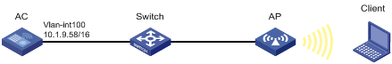
As shown in Figure 8, the switch acts as the DHCP server to assign IP addresses to the AP and the client. The AP provides wireless services with the SSID trade-off.
Configuration procedures
1. Create VLAN 100.
<AC> system-view
[AC] vlan 100
[AC-vlan100] quit
2. Create VLAN-interface 100 and assign it an IP address.
[AC] interface vlan-interface 100
[AC-Vlan-interface100] ip address 10.1.9.58 16
[AC-Vlan-interface100] quit
3. Create the manual AP ap1, and specify the AP model and serial ID.
[AC] wlan ap ap1 model WA4320i-ACN
[AC-wlan-ap-ap1] serial-id 219801A0CNC138011454
[AC-wlan-ap-ap1] quit
4. Configure a service template and bind it to the AP radio:
# Create the service template service1, set the SSID to trade-off, assign clients coming online through the service template to VLAN 100, and enable the service template.
[AC] wlan service-template service1
[AC-wlan-st-service1] ssid trade-off
[AC-wlan-st-service1] vlan 100
[AC-wlan-st-service1] service-template enable
[AC-wlan-st-service1] quit
# Set the working channel to channel 157 for radio 1 of the AP.
[AC-wlan-ap-ap1] radio 1
[AC-wlan-ap-ap1-radio-1] channel 157
# Bind service template service1 to radio 1.
[AC-wlan-ap-ap1-radio-1] radio enable
[AC-wlan-ap-ap1-radio-1] service-template service1
[AC-wlan-ap-ap1-radio-1] quit
[AC-wlan-ap-ap1] quit
Verifying the configuration
# Verify that the SSID is trade-off, and the service template is enabled.
[AC] display wlan service-template verbose
Service template name : service1
Description : Not configured
SSID : trade-off
SSID-hide : Disabled
User-isolation : Disabled
Service template status : Enabled
Maximum clients per BSS : Not configured
Frame format : Dot3
Seamless roam status : Disabled
Seamless roam RSSI threshold : 50
Seamless roam RSSI gap : 20
VLAN ID : 100
AKM mode : Not configured
Security IE : Not configured
Cipher suite : Not configured
TKIP countermeasure time : 0 s
PTK life time : 43200 s
GTK rekey : Enabled
GTK rekey method : Time-based
GTK rekey time : 86400 s
GTK rekey client-offline : Disabled
User authentication mode : Bypass
Intrusion protection : Disabled
Intrusion protection mode : Temporary-block
Temporary block time : 180 sec
Temporary service stop time : 20 sec
Fail VLAN ID : Not configured
802.1X handshake : Disabled
802.1X handshake secure : Disabled
802.1X domain : my-domain
MAC-auth domain : Not configured
Max 802.1X users per BSS : 4096
Max MAC-auth users per BSS : 4096
802.1X re-authenticate : Enabled
Authorization fail mode : Online
Accounting fail mode : Online
Authorization : Permitted
Key derivation : SHA1
PMF status : Disabled
Hotspot policy number : Not configured
Forwarding policy status : Disabled
Forwarding policy name : Not configured
Forwarder : AC
FT status : Disabled
QoS trust : Port
QoS priority : 0
# Associate the client with the AP. (Details not shown.)
# Verify that the client can access the WLAN.
[AC] display wlan client service-template service1
Total number of clients: 1
MAC address Username AP name RID IP address IPv6 address VLAN
0023-8933-223b N/A ap1 1 3.0.0.3 100
Whitelist configuration example
Network requirements
As shown in Figure 9, configure the whitelist to permit only the client whose MAC address is 0000-000f-1211 to access the WLAN.
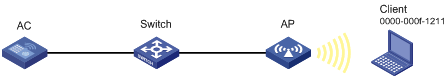
Configuration procedures
# Add the MAC address 0000-000f-1211 to the whitelist.
[AC] wlan whitelist mac-address 0000-000f-1211
Verifying the configuration
# Verify that the MAC address 0000-000f-1211 is in the whitelist.
Total number of clients: 1
MAC addresses:
0000-000f-1211
Static blacklist configuration example
Network requirements
As shown in Figure 10, configure the static blacklist to forbid the client whose MAC address is 0000-000f-1211 to access the WLAN.

Configuration procedures
# Add the MAC address 0000-000f-1211 to the static blacklist.
[AC] wlan static-blacklist mac-address 0000-000f-1211
Verifying the configuration
# Verify that the MAC address 0000-000f-1211 is in the static blacklist.
[AC] display wlan blacklist static
Total number of clients: 1
MAC addresses:
0000-000f-1211