- Table of Contents
-
- 01-Access Volume
- 00-Access Volume Organization
- 01-Ethernet Interface Configuration
- 02-Link Aggregation Configuration
- 03-Port Isolation Configuration
- 04-Service Loopback Group Configuration
- 05-DLDP Configuration
- 06-Smart Link Configuration
- 07-LLDP Configuration
- 08-VLAN Configuration
- 09-GVRP Configuration
- 10-QinQ Configuration
- 11-BPDU Tunneling Configuration
- 12-VLAN Mapping Configuration
- 13-Ethernet OAM Configuration
- 14-Connectivity Fault Detection Configuration
- 15-EPON-OLT Configuration
- 16-MSTP Configuration
- 17-RRPP Configuration
- 18-Mirroring Configuration
- Related Documents
-
| Title | Size | Download |
|---|---|---|
| 18-Mirroring Configuration | 204.01 KB |
Table of Contents
1 Port Mirroring Configuration
Introduction to Port Mirroring
Classification of Port Mirroring
Other Functions Supported by Port Mirroring
Configuring Local Port Mirroring
Configuring Remote Port Mirroring
Displaying and Maintaining Port Mirroring
Port Mirroring Configuration Examples
Local Port Mirroring Configuration Example
Remote Port Mirroring Configuration Example
Local Port Mirroring Configuration Example for ONUs
2 Traffic Mirroring Configuration
Remote Traffic Mirroring Overview
Configuring Remote Traffic Mirroring
Displaying and Maintaining Traffic Mirroring
Traffic Mirroring Configuration Examples
Traffic Mirroring Configuration Example
Remote Traffic Mirroring Configuration Example
When configuring port mirroring, go to these sections for information you are interested in:
l Introduction to Port Mirroring
l Displaying and Maintaining Port Mirroring
l Port Mirroring Configuration Examples
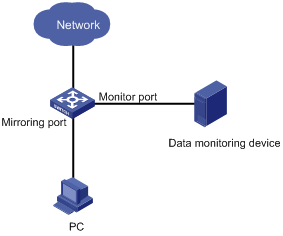
Introduction to Port Mirroring
Port mirroring allows you to duplicate the packets passing specified ports to the monitor port. As monitor ports usually have data monitoring devices connected to them, you can analyze the packets duplicated to the monitor port on these devices so as to monitor and troubleshoot the network.
Figure 1-1 A port mirroring implementation
Classification of Port Mirroring
There are two kinds of port mirroring: local port mirroring and remote port mirroring.
l Local port mirroring copies packets passing through one or more mirroring ports (also known as source ports) of a device to the monitor port (also known destination port) for analysis and monitoring purpose. In this case, the mirroring ports and the monitor port are located on the same device.
l Remote port mirroring implements port mirroring between multiple devices. That is, the mirroring ports and the monitor port can be located on different devices in a network. Currently, remote port mirroring can only be implemented on Layer 2.
Implementing Port Mirroring
Port mirroring is implemented through port mirroring groups, which fall into these three categories: local port mirroring group, remote source port mirroring group, and remote destination port mirroring group. Two port mirroring implementation modes are introduced in the following section.
Local port mirroring
Local port mirroring is implemented by local port mirroring group.
In this mode, the mirroring ports and the monitor port are in the same local port mirroring group. Packets passing through the mirroring ports are duplicated and then are forwarded to the monitor port.
Remote port mirroring
Remote port mirroring is achieved through the cooperation of remote source port mirroring group and remote destination port mirroring group.
Figure 1-2 illustrates a remote port mirroring implementation.
Figure 1-2 A remote mirroring implementation
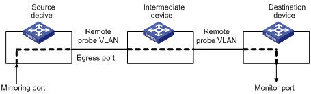
The devices in Figure 1-2 function as follows:
l Source device
Source device contains mirroring ports, and remote source port mirroring groups are created on source devices. A source device duplicates the packets passing the mirroring ports on it and sends them to the egress port. The packets are then broadcast in the remote probe VLAN and are received by the intermediate device or destination device.
l Intermediate device
Intermediate devices are used to connect source devices and destination devices. An intermediate device forwards the mirrored packets to the next intermediate device or the destination device. If the source device is directly connected to the destination device, no intermediate device is needed. In a remote probe VLAN, the source devices and the destination device need to be able to communicate with one another on Layer 2.
l Destination device
Destination device contains the monitor port, and remote destination port mirroring groups are created on destination devices. Upon receiving a mirrored packet, the destination device checks to see if the VLAN ID of the received packet is the same as that of the remote probe VLAN of the remote destination port mirroring group. If yes, the destination device forwards the packet to the monitoring device through the monitor port.
Other Functions Supported by Port Mirroring
Port mirroring group supports inter-board mirroring, which means that the monitor port and mirroring ports can be located on different boards of a device.
In addition, in a port mirroring group, a monitor port can monitor multiple mirroring ports simultaneously in the mirroring group.
Configuring Port Mirroring
Configuring Local Port Mirroring
Configuring local port mirroring
Follow these steps to configure local port mirroring:
|
Use the command… |
Remarks |
||
|
Enter system view |
system-view |
— |
|
|
Create a local mirroring group |
mirroring-group group-id local |
Required |
|
|
Add ports to the port mirroring group as mirroring ports |
In system view |
mirroring-group group-id mirroring-port mirroring-port-list { both | inbound | outbound } |
Use either approach. You can add ports to a port mirroring group as mirroring ports in either system view or interface view. In system view, you can add multiple ports to a port mirroring group at one time. While in interface view, you can only add the current port to a port mirroring group. |
|
In interface view |
interface interface-type interface-number |
||
|
[ mirroring-group group-id ] mirroring-port { both | inbound | outbound } |
|||
|
quit |
|||
|
Add a port to the mirroring group as the monitor port |
In system view |
mirroring-group group-id monitor-port monitor-port-id |
Use either approach. You can add a monitor port to a port mirroring group in either system view or interface view. They achieve the same purpose. |
|
In interface view |
interface interface-type interface-number |
||
|
[ mirroring-group group-id ] monitor-port |
|||
![]()
l A local mirroring group is effective only when it has both mirroring ports and the monitor port configured.
l It is not recommended to enable STP, RSTP or MSTP on the monitor port; otherwise, the mirroring function may be affected.
l Do not use the monitor port for any purpose other than port mirroring.
l The mirroring ports and the monitor port cannot be the member ports of the current mirroring group.
l Before adding the monitor port to a port mirroring group, make sure the port mirroring group exists. A mirroring group can have only one monitor port.
l Do not configure a port accessing an RRPP ring as the monitor port of a mirroring group.
Configuring local port mirroring for an ONU
An S7500E switch installed with an OLT card can work as an OLT in an EPON system. For detailed information about an EPON system, refer to the Introduction to EPON System part in EPON-OLT Configuration.
In an EPON system, an OLT can remotely manage and maintain ONUs. An S7500E switch can configure local port mirroring for ONUs to mirror the incoming or outgoing traffic of an UNI of an ONU to another UNI of the ONU.
Follow these steps to configure local port mirroring for UNIs:
|
To do... |
Use the command... |
Remarks |
|
Enter system view |
system-view |
— |
|
Enter ONU port view |
interface interface-type interface-number |
— |
|
Configure a mirroring port and the traffic direction to be monitored |
uni uni-number mirroring-port { both | inbound | outbound } |
Required |
|
Configure the monitor port |
uni uni-number monitor-port |
Required Once a port is configured to be the monitor port for port mirroring, the port no longer forwards normal traffic; instead, it starts to forward only the copied traffic. |
![]()
When a UNI is configured as the monitor port for port mirroring, it is recommended that you set the VLAN operation mode of the port to transparent so that it will forward packet without making any change. For details, refer to EPON-OLT Configuration in the Access Volume.
Configuring Remote Port Mirroring
Configuring a remote source mirroring group
Follow these steps to configure a remote port mirroring group
|
To do… |
Use the command… |
Remarks |
|
|
Enter system view |
system-view |
— |
|
|
Create a remote source mirroring group |
mirroring-group group-id remote-source |
Required |
|
|
Add ports to the mirroring group as mirroring ports |
In system view |
mirroring-group group-id mirroring-port mirroring-port-list { both | inbound | outbound } |
Use either approach. You can add ports to a source port mirroring group in either system view or interface view. They achieve the same purpose. |
|
In interface view |
interface interface-type interface-number |
||
|
[ mirroring-group group-id ] mirroring-port { both | inbound | outbound } |
|||
|
quit |
|||
|
Add a port to the mirroring group as the egress port |
In system view |
mirroring-group group-id monitor-egress monitor-egress-port-id |
Use either approach. You can add ports to a source mirroring group in either system view or interface view. They achieve the same purpose. |
|
In interface view |
interface interface-type interface-number |
||
|
mirroring-group group-id monitor-egress |
|||
|
quit |
|||
|
Configure the remote probe VLAN for the mirroring group |
mirroring-group group-id remote-probe vlan rprobe-vlan-id |
Required |
|
![]()
l All ports in a remote mirroring group belong to the same device. A remote source mirroring group can have only one egress port.
l The egress port cannot be a member port of the current mirroring group.
l It is not recommended to add the mirroring ports to the remote probe VLAN, which can be used for remote mirroring only.
l It is not recommended to configure STP, RSTP, MSTP, 802.1X, IGMP Snooping, static ARP and MAC address learning on the egress port; otherwise, the mirroring function may be affected.
l Only existing static VLANs can be configured as remote probe VLANs. To remove a VLAN operating as a remote probe VLAN, you need to restore it to a normal VLAN first. A remote port mirroring group gets invalid if its remote probe VLAN is removed.
l A port can belong to only one port mirroring group. A VLAN can be the remote probe VLAN of only one port mirroring group.
Configuring a remote destination port mirroring group
Follow these steps to configure a remote destination port mirroring group:
|
To do… |
Use the command… |
Remarks |
|
|
Enter system view |
system-view |
— |
|
|
Create a remote destination port mirroring group |
mirroring-group group-id remote-destination |
Required |
|
|
Configure the remote probe VLAN for the port mirroring group |
mirroring-group group-id remote-probe vlan rprobe-vlan-id |
Required |
|
|
Add a port to the port mirroring group as the monitor port |
In system view |
mirroring-group group-id monitor-port monitor-port-id |
Use either approach. You can add a port to a remote port mirroring group as the monitor port in either system view or interface view. They achieve the same purpose. |
|
In interface view |
interface interface-type interface-number |
||
|
[ mirroring-group group-id ] monitor-port |
|||
|
quit |
|||
|
Enter view of the monitor port |
interface interface-type interface-number |
— |
|
|
Add the port to the remote probe VLAN |
The port is an access port |
port access vlan rprobe-vlan-id |
Perform one of these three operations according to the port type. |
|
The port is a trunk port |
port trunk permit vlan rprobe-vlan-id |
||
|
The port is a hybrid port |
port hybrid vlan rprobe-vlan-id { tagged | untagged } |
||
![]()
l The monitor port for remote port mirroring cannot be a member port of the current mirroring group.
l The monitor port for remote port mirroring can be an access, trunk, or hybrid port. It must be assigned to the remote probe VLAN.
l Do not enable STP, RSTP or MSTP on the monitor port for remote port mirroring. Otherwise, the mirroring function may be affected.
l Do not use the monitor port for remote port mirroring for any purpose other than port mirroring.
l Only existing static VLANs can be configured as remote probe VLANs. To remove a VLAN operating as a remote probe VLAN, you need to restore it to a normal VLAN first. A remote port mirroring group gets invalid if its remote probe VLAN is removed.
l Use a remote probe VLAN for remote port mirroring only.
l A port can belong to only one port mirroring group. A VLAN can be the remote probe VLAN of only one port mirroring group.
l Do not configure a port accessing an RRPP ring as the monitor port of a mirroring group.
Displaying and Maintaining Port Mirroring
|
To do… |
Use the command… |
Remarks |
|
Display the configuration of a port mirroring group |
display mirroring-group { group-id | all | local | remote-destination | remote-source } |
Available in any view |
Port Mirroring Configuration Examples
Local Port Mirroring Configuration Example
Network requirements
The departments of a company connect to each other through Ethernet switches:
l Research and Development (R&D) department is connected to Switch C through GigabitEthernet 2/0/1.
l Marketing department is connected to Switch C through GigabitEthernet 2/0/2.
l Data monitoring device is connected to Switch C through GigabitEthernet 2/0/3
The administrator wants to monitor the packets received on and sent from the R&D department and the marketing department through the data monitoring device.
Use the local port mirroring function to meet the requirement. Perform the following configurations on Switch C.
l Configure GigabitEthernet 2/0/1 and GigabitEthernet 2/0/2 as mirroring ports.
l Configure GigabitEthernet 2/0/3 as the monitor port.
Network diagram
Figure 1-3 Network diagram for local port mirroring configuration
Configuration procedure
l Configuration on Switch C
# Create a local port mirroring group.
<SwitchC> system-view
[SwitchC] mirroring-group 1 local
# Add port GigabitEthernet 2/0/1 and GigabitEthernet 2/0/2 to the port mirroring group as mirroring ports. Add port GigabitEthernet 2/0/3 to the port mirroring group as the monitor port.
[SwitchC] mirroring-group 1 mirroring-port GigabitEthernet 2/0/1 GigabitEthernet 2/0/2 both
[SwitchC] mirroring-group 1 monitor-port GigabitEthernet 2/0/3
# Display the configuration of all the port mirroring groups.
[SwitchC] display mirroring-group all
mirroring-group 1:
type: local
status: active
mirroring port:
GigabitEthernet2/0/1 both
GigabitEthernet2/0/2 both
monitor port: GigabitEthernet2/0/3
After finishing the configuration, you can monitor all the packets received and sent by R&D department and Marketing department on the Data monitoring device.
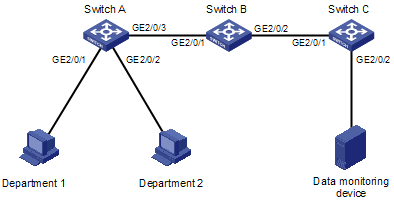
Remote Port Mirroring Configuration Example
Network requirements
The departments of a company connect to each other through Ethernet switches:
l Department 1 is connected to GigabitEthernet 2/0/1 of Switch A.
l Department 2 is connected to GigabitEthernet 2/0/2 of Switch A.
l GigabitEthernet 2/0/3 of Switch A connects to GigabitEthernet 2/0/1 of Switch B.
l GigabitEthernet 2/0/2 of Switch B connects to GigabitEthernet 2/0/1 of Switch C.
l The data monitoring device is connected to GigabitEthernet 2/0/2 of Switch C.
The administrator wants to monitor the packets from Department 1 and 2 through the data monitoring device.
Use the remote port mirroring function to meet the requirement. Perform the following configurations:
l Use Switch A as the source device, Switch B as the intermediate device, and Switch C as the destination device.
l On Switch A, create a remote source mirroring group; create VLAN 2 and configure it as the remote probe VLAN; add ports GigabitEthernet 2/0/1 and GigabitEthernet 2/0/2 to the port mirroring group as two mirroring ports. Configure port GigabitEthernet 2/0/3 as the egress port.
l Configure port GigabitEthernet 2/0/3 of Switch A, port GigabitEthernet 2/0/1 and GigabitEthernet 2/0/2 of Switch B, and port GigabitEthernet 2/0/1 of Switch C as trunk ports and assign them to VLAN 2.
l Create a remote destination mirroring group on Switch C. Configure VLAN 2 as the remote probe VLAN and port GigabitEthernet 2/0/2, to which the data monitoring device is connected, as the monitor port.
Network diagram
Figure 1-4 Network diagram for remote port mirroring configuration
Configuration procedure
1) Configuration on Switch A
# Create a remote source port mirroring group.
<SwitchA> system-view
[SwitchA] mirroring-group 1 remote-source
# Create VLAN 2.
[SwitchA] vlan 2
[SwitchA-vlan2] quit
# Configure VLAN 2 as the remote probe VLAN of the remote port mirroring group. Add ports GigabitEthernet 2/0/1 and GigabitEthernet 2/0/2 to the remote port mirroring group as mirroring ports. Configure port GigabitEthernet 2/0/3 as the egress port.
[SwitchA] mirroring-group 1 remote-probe vlan 2
[SwitchA] mirroring-group 1 mirroring-port GigabitEthernet 2/0/1 GigabitEthernet 2/0/2 inbound
[SwitchA] mirroring-group 1 monitor-egress GigabitEthernet 2/0/3
# Configure port GigabitEthernet 2/0/3 as a trunk port and assign it to VLAN 2.
[SwitchA] interface GigabitEthernet 2/0/3
[SwitchA-GigabitEthernet2/0/3] port link-type trunk
[SwitchA-GigabitEthernet2/0/3] port trunk permit vlan 2
2) Configuration on Switch B
# Configure port GigabitEthernet 2/0/1 as a trunk port and assign it to VLAN 2.
<SwitchB> system-view
[SwitchB] interface GigabitEthernet 2/0/1
[SwitchB-GigabitEthernet2/0/1] port link-type trunk
[SwitchB-GigabitEthernet2/0/1] port trunk permit vlan 2
[SwitchB-GigabitEthernet2/0/1] quit
# Configure port GigabitEthernet 2/0/2 as a trunk port and assign it to VLAN 2.
[SwitchB] interface GigabitEthernet 2/0/2
[SwitchB-GigabitEthernet2/0/2] port link-type trunk
[SwitchB-GigabitEthernet2/0/2] port trunk permit vlan 2
3) Configuration on Switch C
# Configure port GigabitEthernet 2/0/1 as a trunk port and assign it to VLAN 2.
<SwitchC> system-view
[SwitchC] interface GigabitEthernet 2/0/1
[SwitchC-GigabitEthernet2/0/1] port link-type trunk
[SwitchC-GigabitEthernet2/0/1] port trunk permit vlan 2
[SwitchC-GigabitEthernet2/0/1] quit
# Create a remote destination port mirroring group.
[SwitchC] mirroring-group 1 remote-destination
# Create VLAN 2.
[SwitchC] vlan 2
[SwitchC-vlan2] quit
# Configure VLAN 2 as the remote probe VLAN of the remote destination port mirroring group. Add port GigabitEthernet 2/0/2 to the remote destination port mirroring group as the monitor port.
[SwitchC] mirroring-group 1 remote-probe vlan 2
[SwitchC] mirroring-group 1 monitor-port GigabitEthernet 2/0/2
[SwitchC] interface GigabitEthernet 2/0/2
[SwitchC-GigabitEthernet2/0/2] port access vlan 2
After finishing the configuration, you can monitor all the packets sent by Department 1 and Department 2 on the Data monitoring device.
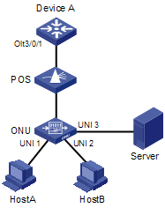
Local Port Mirroring Configuration Example for ONUs
Network requirements
As shown in Figure 1-5, the customer network is as described below:
l OLT 3/0/1 of Device A (an S7500E switch) is connected to ONU 3/0/1:1 of an ONU. The ONU is connected to hosts and a server (a data monitoring device).
l Host A, Host B, and Server are connected to UNI 1, UNI 2, and UNI 3 of the ONU respectively.
l On Device, remotely configure local port mirroring for the ONU to mirror the traffic received on UNI 1 to UNI 3, so that Server can collect all traffic sent by Host A.
Network diagram
Figure 1-5 Network diagram for local port mirroring configuration
Configuration procedure
# Enter system view.
<DeviceA> system-view
# Enter ONU port view.
[DeviceA] interface Onu 3/0/1:1
# Configure UNI 1 as the mirroring port for local port mirroring and specify to mirror traffic received on UNI 1.
[DeviceA-Onu3/0/1:1] uni 1 mirroring-port inbound
# Configure UNI 3 as the monitor port for local port mirroring.
[DeviceA-Onu3/0/1:1] uni 3 monitor-port
After the configuration above, you can monitor all the packets that Host A sends on Server.
When configuring traffic mirroring, go to these sections for information you are interested in:
l Configuring Traffic Mirroring
l Displaying and Maintaining Traffic Mirroring
l Traffic Mirroring Configuration Examples
Traffic Mirroring Overview
Traffic Mirroring Overview
Traffic mirroring is implemented by a QoS policy, which defines certain match criteria to match the packets to be mirrored and defines the action of mirroring such packets to the specified destination.
Depending on different types of mirroring destinations, there are two types of traffic mirroring:
l Mirroring to port: The desired traffic on a source port is replicated and sent to a destination port.
l Mirroring to CPU: The desired traffic on a source port is replicated and sent to the CPU on the board of the port for further analysis.
Remote Traffic Mirroring Overview
Remote traffic mirroring combines traffic mirroring with remote port mirroring to use a remote mirroring group to mirror local packets matching the specified criteria to the specified destination port on a remote device.
Remote traffic mirroring is implemented as follows: configure traffic mirroring on the local device to mirror packets matching certain criteria to an egress port; configure a remote source mirroring group on the local device and specify the destination port for traffic mirroring as the egress port, so that packets sent to the destination port by traffic mirroring can be mirrored to the remote device by remote port mirroring.
Configuring Traffic Mirroring
Configuring Traffic Mirroring
Follow these steps to configure traffic mirroring:
|
To do… |
Use the command… |
Remarks |
|
Enter system view |
system-view |
— |
|
Create a class and enter the corresponding class view |
traffic classifier classifier-name [ operator { and | or } ] |
Required By default, the and keyword is specified. That is, the relation between the rules in the class view is logic AND. This operation leads you to class view. |
|
Configure the match criteria |
if-match match-criteria |
Required |
|
Return to system view |
quit |
— |
|
Create a traffic behavior and enter traffic behavior view |
traffic behavior behavior-name |
Required |
|
Configure the traffic mirroring action for the traffic behavior |
mirror-to { cpu | interface interface-type interface-number } |
Required |
|
Return to system view |
quit |
— |
|
Create a QoS policy and enter QoS policy view |
qos policy policy-name |
— |
|
Associate the class with the traffic behavior |
classifier classifier-name behavior behavior-name |
Required |
|
Return to system view |
quit |
— |
|
Apply the QoS policy |
Refer to QoS Configuration in the QoS Volume |
You can apply a QoS policy to a port, VLAN, or globally on an S7500E switch. |
![]()
Among the boards supported by S7500E switches, the SC series boards support mirroring incoming packets and outgoing packets; the SA and EA series boards only support mirroring incoming packets.
Configuring Remote Traffic Mirroring
To implement remote traffic mirroring, perform the following configurations on the source device and destination device:
Configurations on the source device
l Traffic mirroring configuration: configure traffic mirroring on the source device to mirror packets matching certain criteria to the port connecting to the destination device (assuming the port is Port A). For the detailed configuration procedure, refer to Configuring Traffic Mirroring.
l Remote source mirroring group configuration: configure a remote source mirroring group on the source device, and configure the destination port in traffic mirroring (that is, Port A) as the egress port. For the detailed configuration procedure, refer to Configuring a remote source mirroring group.
![]()
You should specify an arbitrary port as the mirroring port. To prevent packets received/sent by the port from being mirrored to the destination device by the remote source mirroring group, you are recommended to configure an unused port as the mirroring port.
Configurations on the destination device
You need only configure a remote destination mirroring group on the destination device. For the detailed configuration procedure, refer to Configuring a remote destination port mirroring group.
Displaying and Maintaining Traffic Mirroring
|
To do… |
Use the command… |
Remarks |
|
Display the configuration information about the user-defined traffic behavior |
display traffic behavior user-defined behavior-name |
Available in any view |
|
Display the configuration information about the user-defined policy |
display qos policy user-defined policy-name |
Traffic Mirroring Configuration Examples
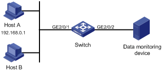
Traffic Mirroring Configuration Example
Network Requirements
The user's network is as described below:
l Host A (with the IP address 192.168.0.1) and Host B are connected to GigabitEthernet 2/0/1 of the switch.
l The data monitoring device is connected to GigabitEthernet 2/0/2 of the switch.
It is required to monitor and analyze packets sent by Host A on the data monitoring device.
Figure 2-1 Network diagram for configuring traffic mirroring to a port
Configuration Procedure
l Configuration on the Switch
# Enter system view.
<Sysname> system-view
# Configure basic IPv4 ACL 2000 to match packets with the source IP address 192.168.0.1.
[Sysname] acl number 2000
[Sysname-acl-basic-2000] rule permit source 192.168.0.1 0
[Sysname-acl-basic-2000] quit
# Create class 1 and use basic ACL 2000 as the match criteria.
[Sysname] traffic classfier 1
[Sysname-classifier-1] if-match acl 2000
[Sysname-classifier-1] quit
# Create traffic behavior 1 and configure the action of mirroring traffic to GigabitEthernet 2/0/2 for the traffic behavior.
[Sysname] traffic behavior 1
[Sysname-behavior-1] mirror-to interface GigabitEthernet 2/0/2
[Sysname-behavior-1] quit
# Create QoS policy 1 and associate traffic behavior 1 with class 1 in the QoS policy.
[Sysname] qos policy 1
[Sysname-policy-1] classifier 1 behavior 1
[Sysname-policy-1] quit
# Apply QoS policy 1 to the inbound direction of GigabitEthernet 2/0/1.
[Sysname] interface GigabitEthernet 2/0/1
[Sysname-GigabitEthernet2/0/1] qos apply policy 1 inbound
After the configurations, you can monitor all packets from Host A on the data monitoring device.
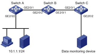
Remote Traffic Mirroring Configuration Example
Network requirements
As shown in Figure 2-2, the customer network is as described below:
l GigabitEthernet 2/0/2 of Switch A is connected to the 10.1.1.1/24 network segment.
l GigabitEthernet 2/0/2 of Switch C is connected to the data monitoring device.
l Switch B connects Switch A and Switch C, as shown in Figure 2-2.
Configure remote traffic mirroring to mirror the packets which are from the 10.1.1.1/24 network segment and received on GigabitEthernet 2/0/2 of Switch A to the data monitoring device.
Network diagram
Figure 2-2 Network diagram for remote traffic mirroring configuration
Configuration procedure
l Configuration on Switch A
# Configure basic IPv4 ACL 2000 to match packets from the 10.1.1.1/24 network segment.
<SwitchA> system-view
[SwitchA] acl number 2000
[SwitchA-acl-basic-2000] rule permit source 10.1.1.1 255.255.255.0
[SwitchA-acl-basic-2000] quit
# Create class 1 and use basic IPv4 ACL 2000 as the match criteria.
[SwitchA] traffic classfier 1
[SwitchA-classifier-1] if-match acl 2000
[SwitchA-classifier-1] quit
# Create behavior 1 and configure the action of mirroring traffic to GigabitEthernet 2/0/1 for the behavior.
[SwitchA] traffic behavior 1
[SwitchA-behavior-1] mirror-to interface GigabitEthernet 2/0/1
[SwitchA-behavior-1] quit
# Create QoS policy 1 and associate class 1 with behavior 1 in the QoS policy.
[SwitchA] qos policy 1
[SwitchA-policy-1] classifier 1 behavior 1
[SwitchA-policy-1] quit
# Apply QoS policy 1 to the inbound direction of GigabitEthernet 2/0/2.
[SwitchA] interface GigabitEthernet 2/0/2
[SwitchA-GigabitEthernet2/0/2] qos apply policy 1 inbound
[SwitchA-GigabitEthernet2/0/2] quit
# Create remote source mirroring group 1.
[SwitchA] mirroring-group 1 remote-source
# Create VLAN 2.
[SwitchA] vlan 2
[SwitchA-vlan2] quit
# Configure VLAN 2 as the remote probe VLAN, GigabitEthernet 2/0/48 as the mirroring port, and GigabitEthernet 2/0/1 as the egress port for the remote source mirroring group.
[SwitchA] mirroring-group 1 remote-probe vlan 2
[SwitchA] mirroring-group 1 mirroring-port GigabitEthernet 2/0/48 inbound
[SwitchA] mirroring-group 1 monitor-egress GigabitEthernet 2/0/1
# Configure GigabitEthernet 2/0/1 as a trunk port and assign it to VLAN 2.
[SwitchA] interface GigabitEthernet 2/0/1
[SwitchA-GigabitEthernet2/0/1] port link-type trunk
[SwitchA-GigabitEthernet2/0/1] port trunk permit vlan 2
l Configuration on Switch B
# Configure GigabitEthernet 2/0/1 as a trunk port and assign it to VLAN 2.
<SwitchB> system-view
[SwitchB] interface GigabitEthernet 2/0/1
[SwitchB-GigabitEthernet2/0/1] port link-type trunk
[SwitchB-GigabitEthernet2/0/1] port trunk permit vlan 2
[SwitchB-GigabitEthernet2/0/1] quit
# Configure GigabitEthernet 2/0/2 as a trunk port and assign it to VLAN 2.
[SwitchB] interface GigabitEthernet 2/0/2
[SwitchB-GigabitEthernet2/0/2] port link-type trunk
[SwitchB-GigabitEthernet2/0/2] port trunk permit vlan 2
l Configuration on Switch C
# Configure GigabitEthernet 2/0/1 as a trunk port and assign it to VLAN 2.
<SwitchC> system-view
[SwitchC] interface GigabitEthernet 2/0/1
[SwitchC-GigabitEthernet2/0/1] port link-type trunk
[SwitchC-GigabitEthernet2/0/1] port trunk permit vlan 2
[SwitchC-GigabitEthernet2/0/1] quit
# Create remote destination mirroring group 1.
[SwitchC] mirroring-group 1 remote-destination
# Create VLAN 2.
[SwitchC] vlan 2
[SwitchC-vlan2] quit
# Configure VLAN 2 as the remote probe VLAN and GigabitEthernet 2/0/2 as the monitor port for the remote destination mirroring group, and configure GigabitEthernet 2/0/2 as an access port and assign it to VLAN 2.
[SwitchC] mirroring-group 1 remote-probe vlan 2
[SwitchC] mirroring-group 1 monitor-port GigabitEthernet 2/0/2
[SwitchC] interface GigabitEthernet 2/0/2
[SwitchC-GigabitEthernet 2/0/2] port access vlan 2
After the configuration above, you can monitor packets from the 10.1.1.1/24 network segment on the data monitoring device.
