- Table of Contents
-
- 01-Access Volume
- 00-Access Volume Organization
- 01-Ethernet Interface Configuration
- 02-Link Aggregation Configuration
- 03-Port Isolation Configuration
- 04-Service Loopback Group Configuration
- 05-DLDP Configuration
- 06-Smart Link Configuration
- 07-LLDP Configuration
- 08-VLAN Configuration
- 09-GVRP Configuration
- 10-QinQ Configuration
- 11-BPDU Tunneling Configuration
- 12-VLAN Mapping Configuration
- 13-Ethernet OAM Configuration
- 14-Connectivity Fault Detection Configuration
- 15-EPON-OLT Configuration
- 16-MSTP Configuration
- 17-RRPP Configuration
- 18-Mirroring Configuration
- Related Documents
-
| Title | Size | Download |
|---|---|---|
| 08-VLAN Configuration | 333.47 KB |
Table of Contents
Configuring Basic VLAN Settings
Configuring Basic Settings of a VLAN Interface
Introduction to Port-Based VLAN
Assigning an Access Port to a VLAN
Assigning a Trunk Port to a VLAN
Assigning a Hybrid Port to a VLAN
Introduction to MAC-Based VLAN
Approaches to Creating MAC Address-to-VLAN Mappings
Configuring a MAC Address-Based VLAN
Protocol-Based VLAN Configuration
Introduction to Protocol-Based VLAN
Configuring a Protocol-Based VLAN
IP Subnet-Based VLAN Configuration
Configuring an IP Subnet-Based VLAN
Displaying and Maintaining VLAN
Displaying and Maintaining Super VLAN
Super VLAN Configuration Example
3 Isolate-User-VLAN Configuration
Displaying and Maintaining Isolate-User-VLAN
Isolate-User-VLAN Configuration Example
Security Mode and Normal Mode of Voice VLANs
Setting a Port to Operate in Automatic Voice VLAN Assignment Mode
Setting a Port to Operate in Manual Voice VLAN Assignment Mode
Displaying and Maintaining Voice VLAN
Voice VLAN Configuration Examples
Automatic Voice VLAN Mode Configuration Example
Manual Voice VLAN Mode Configuration Example
When configuring VLAN, go to these sections for information you are interested in:
l Configuring Basic VLAN Settings
l Configuring Basic Settings of a VLAN Interface
l Port-Based VLAN Configuration
l MAC-Based VLAN Configuration
l Protocol-Based VLAN Configuration
l Displaying and Maintaining VLAN
Introduction to VLAN
VLAN Overview
Ethernet is a network technology based on the Carrier Sense Multiple Access/Collision Detect (CSMA/CD) mechanism. As the medium is shared, collisions and excessive broadcasts cannot be avoided on an Ethernet. To address the issue, virtual LAN (VLAN) was introduced.
The idea is to break a LAN down into separate VLANs, that is, Layer 2 broadcast domains whereby frames are switched between ports assigned to the same VLAN. VLANs are isolated from each other at Layer 2. A VLAN is a bridging domain, and all broadcast traffic is contained within it, as shown in Figure 1-1.
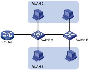
A VLAN is logically divided on an organizational basis rather than on a physical basis. For example, all workstations and servers used by a particular workgroup can be connected to the same LAN, regardless of their physical locations.
VLAN technology delivers the following benefits:
1) Confining broadcast traffic within individual VLANs. This reduces bandwidth waste and improves network performance.
2) Improving LAN security. By assigning user groups to different VLANs, you can isolate them at Layer 2. To enable communication between VLANs, routers or Layer 3 switches are required.
3) Flexible virtual workgroup creation. As users from the same workgroup can be assigned to the same VLAN regardless of their physical locations, network construction and maintenance is much easier and more flexible.
VLAN Fundamentals
To enable a network device to identify frames of different VLANs, a VLAN tag field is inserted into the data link layer encapsulation.
The format of VLAN-tagged frames is defined in IEEE 802.1Q issued by IEEE in 1999.
In the header of a traditional Ethernet data frame, the field after the destination MAC address and the source MAC address is the Type field indicating the upper layer protocol type, as shown in Figure 1-2.
Figure 1-2 The format of a traditional Ethernet frame
![]()
IEEE 802.1Q inserts a four-byte VLAN tag after the DA&SA field, as shown in Figure 1-3.
Figure 1-3 The position and format of VLAN tag
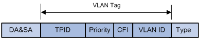
A VLAN tag comprises four fields: tag protocol identifier (TPID), priority, canonical format indicator (CFI), and VLAN ID.
l The 16-bit TPID field indicates that the frame is VLAN-tagged. The value specified by IEEE 802.1Q is 0x8100.
l The 3-bit priority field indicates the 802.1p priority of the frame. For information about frame priority, refer to QoS Configuration in the QoS Volume.
l The 1-bit CFI field specifies whether the MAC addresses are encapsulated in the standard format when packets are transmitted across different media. Value 0 indicates that MAC addresses are encapsulated in the standard format; value 1 indicates that MAC addresses are encapsulated in a non-standard format. The filed is 0 by default.
l The 12-bit VLAN ID field identifies the VLAN the frame belongs to. The VLAN ID range is 0 to 4095. As 0 and 4095 are reserved by the protocol, a VLAN ID actually ranges from 1 to 4094.
When receiving a frame, a network device looks at its VLAN tag to decide how to handle the frame. For more information, refer to section Introduction to Port-Based VLAN.
![]()
l The Ethernet II encapsulation format is used here. Besides the Ethernet II encapsulation format, other encapsulation formats, including 802.2 LLC, 802.2 SNAP, and 802.3 raw, are also supported by Ethernet. The VLAN tag fields are also added to frames encapsulated in these formats for VLAN identification.
l For a frame with multiple VLAN tags, the device handles it according to its outer-most VLAN tag, while transmits its inner VLAN tags as payload.
Types of VLAN
You can implement VLAN based on:
l Port
l MAC address
l Protocol
l IP subnet
l Policy
l Other criteria
This chapter covers port-based VLAN, MAC-based VLAN, protocol-based VLAN, and IP-based VLAN. You can configure the four types of VLANs on a port at the same time. When determining to which VLAN a packet passing through the port should be assigned, the device looks up the VLANs in the default order of MAC-based VLANs, IP-based VLANs, protocol-based VLANs, and port-based VLANs.
Configuring Basic VLAN Settings
Follow these steps to configure basic VLAN settings:
|
To do… |
Use the command… |
Remarks |
|
Enter system view |
system-view |
— |
|
Create VLANs |
vlan { vlan-id1 [ to vlan-id2 ] | all } |
Optional Using this command can create multiple VLANs in bulk. |
|
Enter VLAN view |
vlan vlan-id |
Required If the specified VLAN does not exist, this command creates the VLAN first. By default, only the default VLAN (that is, VLAN 1) exists in the system. |
|
Configure the description of the current VLAN |
description text |
Optional VLAN ID is used by default, for example, VLAN 0001. |
![]()
l As the default VLAN, VLAN 1 cannot be created or removed.
l You cannot manually create or remove VLANs reserved for special purposes.
l Dynamic VLANs cannot be removed with the undo vlan command.
l A VLAN with a QoS policy applied cannot be removed.
l After associating an isolate-user-VLAN with a secondary VLAN, you cannot add ports to, remove ports from, or remove, the VLANs. To do that, remove the association first.
l A VLAN operating as a probe VLAN for remote port mirroring or an RRPP protected VLAN cannot be removed with the undo vlan command. To do that, remove the remote mirroring VLAN or RRPP protected VLAN configuration from it first.
Configuring Basic Settings of a VLAN Interface
For hosts of different VLANs to communicate, you must use a router or Layer 3 switch to perform layer 3 forwarding. To achieve this, VLAN interfaces are used.
VLAN interfaces are virtual interfaces used for Layer 3 communication between different VLANs. They do not exist as physical entities on devices. For each VLAN, you can create one VLAN interface. You can assign the VLAN interface an IP address and specify it as the gateway of the VLAN to forward traffic destined for an IP network segment different from that of the VLAN.
Follow these steps to configure basic settings of a VLAN interface:
|
To do… |
Use the command… |
Remarks |
|
Enter system view |
system-view |
— |
|
Create a VLAN interface and enter VLAN interface view |
interface vlan-interface vlan-interface-id |
Required If the VLAN interface already exists, you enter its view directly. |
|
Assign an IP address to the VLAN interface |
ip address ip-address { mask | mask-length } [ sub ] |
Optional No IP address is assigned to any VLAN interface by default. |
|
Configure the description of the VLAN interface |
description text |
Optional VLAN interface name is used by default, for example, Vlan-interface1 Interface. |
|
Bring up the VLAN interface |
undo shutdown |
Optional By default, a VLAN interface is in the up state. In this case, the VLAN interface is up so long as one port in the VLAN is up and goes down if all ports in the VLAN go down. An administratively shut down VLAN interface however will be in the down state until you bring it up, regardless of how the state of the ports in the VLAN changes. |
![]()
Before creating a VLAN interface for a VLAN, create the VLAN first.
Port-Based VLAN Configuration
Introduction to Port-Based VLAN
Port-based VLANs group VLAN members by port. A port forwards traffic for a VLAN only after it is assigned to the VLAN.
Port link type
Depending on the tag handling mode, the link type of a port can be one of the following three:
l Access. An access port belongs to only one VLAN and usually connects to a user device.
l Trunk. A trunk port can join multiple VLANs to receive and send traffic for them. It usually connects to a network device.
l Hybrid. A hybrid port can join multiple VLANs to receive and send traffic for them. It can connect either a user device or a network device.
A hybrid port is different from a trunk port in that:
l A hybrid port allows traffic of multiple VLANs to pass through untagged.
l A trunk port allows only traffic of the default VLAN to pass through untagged.
Default VLAN
By default, VLAN 1 is the default VLAN for all ports. You can configure the default VLAN for a port as required.
Use the following guidelines when configuring the default VLAN on a port:
l Because an access port can join only one VLAN, its default VLAN is the VLAN to which it belongs and cannot be configured.
l Because a trunk or hybrid port can join multiple VLANs, you can configure a default VLAN for the port.
l You can use a nonexistent VLAN as the default VLAN for a hybrid or trunk port but not for an access port. Therefore, after you remove the VLAN that an access port resides in with the undo vlan command, the default VLAN of the port changes to VLAN 1. The removal of the VLAN specified as the default VLAN of a trunk or hybrid port, however, does not affect the default VLAN setting on the port.
![]()
l Do not set the voice VLAN as the default VLAN of a port in automatic voice VLAN assignment mode. Otherwise, the system prompts error information. For information about voice VLAN, refer to Voice VLAN Configuration.
l The local and remote ports must use the same default VLAN ID for the traffic of the default VLAN to be transmitted properly.
A port configured with the default VLAN handles a frame as follows:
|
Port type |
Actions (in the inbound direction) |
Actions (in the outbound direction) |
|
|
Untagged frame |
Tagged frame |
||
|
Access |
Tag the frame with the default VLAN tag. |
l Receive the frame if its VLAN ID is the same as the default VLAN ID. l Drop the frame if its VLAN ID is different from the default VLAN ID. |
Remove the default VLAN tag and send the frame. |
|
Trunk |
Check whether the default VLAN is carried on the port: l If yes, tag the frame with the default VLAN tag. l If not, drop the frame. |
l Receive the frame if its VLAN is carried on the port. l Drop the frame if its VLAN is not carried on the port. |
l Remove the tag and send the frame if the frame carries the default VLAN tag. l Send the frame without removing the tag if its VLAN is carried on the port but is different from the default one. |
|
Hybrid |
Send the frame if its VLAN is carried on the port. The frame is sent with the VLAN tag removed or intact depending on your configuration with the port hybrid vlan command. This is true of the default VLAN. |
||
Assigning an Access Port to a VLAN
You can assign an access port to a VLAN in VLAN view, Ethernet port view, Layer-2 aggregate interface view, or port group view.
1) In VLAN view
Follow these steps to assign one or multiple access ports to a VLAN in VLAN view:
|
To do… |
Use the command… |
Remarks |
|
Enter system view |
system-view |
— |
|
Enter VLAN view |
vlan vlan-id |
Required If the specified VLAN does not exist, this command creates the VLAN first. |
|
Assign one or a group of access ports to the current VLAN |
port interface-list |
Required By default, all ports belong to VLAN 1. |
2) In interface or port group view
Follow these steps to assign an access port (in Ethernet port view) or multiple access ports (in Layer-2 aggregate interface view or port group view) to a VLAN:
|
To do… |
Use the command… |
Remarks |
|
|
Enter system view |
system-view |
— |
|
|
Enter Ethernet port view/port group view/Layer-2 aggregate interface view |
Enter Ethernet port view |
interface interface-type interface-number |
Required Use either command. l In Ethernet port view, the subsequent configurations apply to the current port. l In port group view, the subsequent configurations apply to all ports in the port group. l In Layer-2 aggregate interface view, the subsequent configurations apply to the Layer-2 aggregate interface and all its member ports. |
|
Enter Layer-2 aggregate interface view |
interface bridge-aggregation interface-number |
||
|
Enter port group view |
port-group manual port-group-name |
||
|
Configure the link type of the port or ports as access |
port link-type access |
Optional The link type of a port is access by default. |
|
|
Assign the current access port(s) to a VLAN |
port access vlan vlan-id |
Optional By default, all access ports belong to VLAN 1. |
|
![]()
Before assigning an access port to a VLAN, create the VLAN first.
Assigning a Trunk Port to a VLAN
A trunk port can carry multiple VLANs. You can assign it to a VLAN in Ethernet port view, Layer-2 aggregate interface view, or port group view.
Follow these steps to assign a trunk port to one or multiple VLANs:
|
To do… |
Use the command… |
Remarks |
|
|
Enter system view |
system-view |
— |
|
|
Enter Ethernet port view/port group view/Layer-2 aggregate interface view |
Enter Ethernet port view |
interface interface-type interface-number |
Required Use either command. l In Ethernet port view, the subsequent configurations apply to the current port. l In port group view, the subsequent configurations apply to all ports in the port group. l In Layer-2 aggregate interface view, the subsequent configurations apply to the Layer-2 aggregate interface and all its member ports. |
|
Enter Layer-2 aggregate interface view |
interface bridge-aggregation interface-number |
||
|
Enter port group view |
port-group manual port-group-name |
||
|
Configure the link type of the port or ports as trunk |
port link-type trunk |
Required |
|
|
Assign the trunk port(s) to the specified VLAN(s) |
port trunk permit vlan { vlan-id-list | all } |
Required By default, a trunk port carries only VLAN 1. |
|
|
Configure the default VLAN of the trunk port(s) |
port trunk pvid vlan vlan-id |
Optional VLAN 1 is the default VLAN by default. |
|
![]()
l To change the link type of a port from trunk to hybrid or vice versa, you must set the link type to access first.
l The local and remote hybrid ports must use the same default VLAN ID for the traffic of the default VLAN to be transmitted properly.
l After configuring the default VLAN for a trunk port, you must use the port trunk permit vlan command to configure the trunk port to allow packets from the default VLAN to pass through, so that the egress port can forward packets from the default VLAN.
Assigning a Hybrid Port to a VLAN
A hybrid port can carry multiple VLANs. You can assign it to a VLAN in Ethernet port view, Layer-2 aggregate interface view, or port group view.
Follow these steps to assign a hybrid port to one or multiple VLANs:
|
To do… |
Use the command… |
Remarks |
|
|
Enter system view |
system-view |
— |
|
|
Enter Ethernet port view/port group view/Layer-2 aggregate interface view |
Enter Ethernet port view |
interface interface-type interface-number |
Required Use either command. l In Ethernet port view, the subsequent configurations apply to the current port. l In port group view, the subsequent configurations apply to all ports in the port group. l In Layer-2 aggregate interface view, the subsequent configurations apply to the Layer-2 aggregate interface and all its member ports. |
|
Enter Layer-2 aggregate interface view |
interface bridge-aggregation interface-number |
||
|
Enter port group view |
port-group manual port-group-name |
||
|
Configure the link type of the port(s) as hybrid |
port link-type hybrid |
Required |
|
|
Assign the hybrid port(s) to the specified VLAN(s) |
port hybrid vlan vlan-id-list { tagged | untagged } |
Required By default, a hybrid port allows only packets of VLAN 1 to pass through untagged. |
|
|
Configure the default VLAN of the hybrid port |
port hybrid pvid vlan vlan-id |
Optional VLAN 1 is the default by default. |
|
![]()
l To change the link type of a port from trunk to hybrid or vice versa, you must set the link type to access first.
l Before assigning a hybrid port to a VLAN, create the VLAN first.
l The local and remote hybrid ports must use the same default VLAN ID for the traffic of the default VLAN to be transmitted properly.
l After configuring the default VLAN for a hybrid port, you must use the port hybrid vlan command to configure the hybrid port to allow packets from the default VLAN to pass through, so that the egress port can forward packets from the default VLAN.
MAC-Based VLAN Configuration
Introduction to MAC-Based VLAN
MAC-based VLANs group VLAN members by MAC address. They only apply to untagged frames.
When receiving an untagged frame, the device looks up the list of MAC-to-VLAN mappings based on the MAC address of the frame for a match. If a match is found, the system forwards the frame in the corresponding VLAN. If no match is found, the system looks up other types of VLANs to make the forwarding decision.
MAC-based VLANs are mostly used in conjunction with security technologies such as 802.1X to provide secure, flexible network access for terminal devices.
Approaches to Creating MAC Address-to-VLAN Mappings
In addition to creating MAC address-to-VLAN mappings at the CLI, you can use an authentication server to automatically issue MAC address-to-VLAN mappings.
l Manually Static configuration (through CLI)
You can associate MAC addresses with VLANs by using corresponding commands.
l Automatic configuration through the authentication server (that is, VLAN issuing)
The device associates MAC addresses with VLANs dynamically based on the information provided by the authentication server. If a user goes offline, the corresponding MAC address-to-VLAN association is removed automatically. Automatic configuration requires MAC address-to–VLAN mapping be configured on the authentication server. For detailed information, refer to 802.1X Configuration in the Security Volume.
The two configuration approaches can be used at the same time, that is, you can configure a MAC address-to-VLAN entry on both the local device and the authentication server at the same time. Note that the MAC address-to-VLAN entry configuration takes effect only when the configuration on the local device is consistent with that on the authentication server. Otherwise, the previous configuration takes effect.
Configuring a MAC Address-Based VLAN
![]()
MAC-based VLANs are available only on hybrid ports.
Follow these steps to configure a MAC-based VLAN:
|
To do... |
Use the command... |
Remarks |
|
|
Enter system view |
system-view |
— |
|
|
Associate MAC addresses with a VLAN |
mac-vlan mac-address mac-address [ mask mac-mask ] vlan vlan-id [ priority priority ] |
Required |
|
|
Enter Ethernet port view or port group view |
Enter Ethernet port view |
interface interface-type interface-number |
Use either command. In Ethernet port view, the subsequent configurations apply only to the current port; in port group view, the subsequent configurations apply to all ports in the port group. |
|
Enter port group view |
port-group manual port-group-name |
||
|
Configure the link type of the port(s) as hybrid |
port link-type hybrid |
Required |
|
|
Configure the current hybrid port(s) to permit packets of specific MAC-based VLANs to pass through |
port hybrid vlan vlan-id-list { tagged | untagged } |
Required By default, a hybrid port only permits the packets of VLAN 1 to pass through. |
|
|
Enable MAC-based VLAN |
mac-vlan enable |
Required Disabled by default |
|
|
Configure VLAN matching precedence |
vlan precedence { mac-vlan | ip-subnet-vlan } |
Optional By default, VLANs are preferentially matched based on MAC addresses. |
|
![]()
When the source MAC address of an untagged packet matches an MAC-VLAN entry and an OUI address used in voice VLAN at the same time, the packet will be assigned to the MAC-based VLAN. As a result, the packet will not be able to enter the voice VLAN. Therefore, we recommend you not to configure the OUI addresses of voice packets in MAC-VLAN entries.
Protocol-Based VLAN Configuration
Introduction to Protocol-Based VLAN
![]()
Protocol-based VLANs are only applicable on hybrid ports.
In this approach, inbound packets are assigned to different VLANs based on their protocol types and encapsulation formats. The protocols that can be used for VLAN assignment include IP, IPX, and AppleTalk (AT). The encapsulation formats include Ethernet II, 802.3 raw, 802.2 LLC, and 802.2 SNAP.
A protocol-based VLAN is defined by a protocol template comprised of encapsulation format and protocol type. A port can be associated with multiple protocol templates. An untagged packet reaching a port associated with protocol-based VLANs will be processed as follows.
l If the packet matches a protocol template, the packet will be tagged with the VLAN tag corresponding to the protocol template.
l If the packet matches no protocol template, the packet will be tagged with the default VLAN ID of the port.
The port processes a tagged packet as it processes tagged packets of a port-based VLAN.
l If the port permits the VLAN ID of the packet to pass through, the port forwards the packet.
l If the port does not permit the VLAN ID of the packet to pass through, the port drops the packet.
This feature is mainly used to assign packets of the specific service type to a specific VLAN.
Configuring a Protocol-Based VLAN
Follow these steps to configure a protocol-based VLAN:
|
To do… |
Use the command… |
Remarks |
|
|
Enter system view |
system-view |
— |
|
|
Enter VLAN view |
vlan vlan-id |
Required If the specified VLAN does not exist, this command creates the VLAN first. |
|
|
Create a protocol template for the VLAN |
protocol-vlan [ protocol-index ] { at | ipv4 | ipv6 | ipx { ethernetii | llc | raw | snap } | mode { ethernetii etype etype-id | llc { dsap dsap-id [ ssap ssap-id ] | ssap ssap-id } | snap etype etype-id } } |
Required |
|
|
Exit VLAN view |
quit |
— |
|
|
Enter Ethernet port view, Layer-2 aggregate interface view, or port group view |
Enter Ethernet port view |
interface interface-type interface-number |
Required Use either command. l In Ethernet port view, the subsequent configurations apply to the current port. l In port group view, the subsequent configurations apply to all ports in the port group. l In Layer-2 aggregate interface view, the subsequent configurations apply to the Layer-2 aggregate interface and all its member ports. |
|
Enter Layer-2 aggregate interface view |
interface bridge-aggregation interface-number |
||
|
Enter port group view |
port-group manual port-group-name |
||
|
Configure the port link type as hybrid |
port link-type hybrid |
Required |
|
|
Configure current hybrid port(s) to permit the packets of the specified protocol-based VLANs to pass through |
port hybrid vlan vlan-id-list { tagged | untagged } |
Required By default, all hybrid ports permit packets of VLAN 1 to pass through only. |
|
|
Associate the hybrid port(s) with the specified protocol-based VLAN |
port hybrid protocol-vlan vlan vlan-id { protocol-index [ to protocol-end ] | all } |
Required |
|
![]()
l Currently, H3C S7500E series Ethernet switches do not support associating an AppleTalk protocol template with ports.
l Do not configure both the dsap-id and ssap-id arguments in the protocol-vlan command as 0xe0 or 0xff when configuring the user-defined template for llc encapsulation. Otherwise, the encapsulation format of the matching packets will be the same as that of the ipx llc or ipx raw packets respectively.
l When you use the mode keyword to configure a user-defined protocol template, do not set etype-id in ethernetii etype etype-id to 0x0800, 0x8137, 0x809b, or 0x86dd. Otherwise, the encapsulation format of the matching packets will be the same as that of the IPv4, IPX, AppleTalk, and IPv6 packets respectively.
l A protocol-based VLAN on a hybrid port can process only untagged inbound packets, whereas the voice VLAN in automatic mode on a hybrid port can process only tagged voice traffic. Therefore, do not configure a VLAN as both a protocol-based VLAN and a voice VLAN. For more information, refer to Voice VLAN Configuration.
IP Subnet-Based VLAN Configuration
Introduction
In this approach, packets are assigned to VLANs based on their source IP addresses and subnet masks. A port configured with IP subnet-based VLANs assigns a received untagged packet to a VLAN based on the source address of the packet.
This feature is used to assign packets from the specified network segment or IP address to a specific VLAN.
Configuring an IP Subnet-Based VLAN
![]()
This feature is only applicable on hybrid ports.
Follow these steps to configure an IP subnet-based VLAN:
|
To do… |
Use the command… |
Remarks |
|
|
Enter system view |
system-view |
— |
|
|
Enter VLAN view |
vlan vlan-id |
— |
|
|
Associate an IP subnet with the current VLAN |
ip-subnet-vlan [ ip-subnet-index ] ip ip-address [ mask ] |
Required The IP network segment or IP address to be associated with a VLAN cannot be a multicast network segment or a multicast address. |
|
|
Return to system view |
quit |
— |
|
|
Enter Ethernet port view, Layer-2 aggregate interface view, or port group view |
Enter Ethernet port view |
interface interface-type interface-number |
Required Use either command. l In Ethernet port view, the subsequent configurations apply to the current port. l In port group view, the subsequent configurations apply to all ports in the port group. l In Layer-2 aggregate interface view, the subsequent configurations apply to the Layer-2 aggregate interface and all its member ports. |
|
Enter Layer-2 aggregate interface view |
interface bridge-aggregation interface-number |
||
|
Enter port group view |
port-group manual port-group-name |
||
|
Configure port link type as hybrid |
port link-type hybrid |
Required |
|
|
Configure the hybrid port(s) to permit the specified IP subnet-based VLANs to pass through |
port hybrid vlan vlan-id-list { tagged | untagged } |
Required |
|
|
Associate the hybrid port(s) with the specified IP subnet-based VLAN |
port hybrid ip-subnet-vlan vlan vlan-id |
Required |
|
Displaying and Maintaining VLAN
|
To do... |
Use the command… |
Remarks |
|
Display VLAN information |
display vlan [ vlan-id1 [ to vlan-id2 ] | all | dynamic | reserved | static ] |
Available in any view |
|
Display VLAN interface information |
display interface vlan-interface [ vlan-interface-id ] |
Available in any view |
|
Display hybrid ports or trunk ports on the device |
display port { hybrid | trunk } |
Available in any view |
|
Display MAC address-to-VLAN entries |
display mac-vlan { all | dynamic | mac-address mac-address [ mask mac-mask ] | static | vlan vlan-id } |
Available in any view |
|
Display all interfaces with MAC-based VLAN enabled |
display mac-vlan interface |
Available in any view |
|
Display protocol information and protocol indexes of the specified VLANs |
display protocol-vlan vlan { vlan-id [ to vlan-id ] | all } |
Available in any view |
|
Display protocol-based VLAN information on specified interfaces |
display protocol-vlan interface { interface-type interface-number [ to interface-type interface-number ] | all } |
Available in any view |
|
Display IP subnet-based VLAN information and IP subnet indexes of specified VLANs |
display ip-subnet-vlan vlan { vlan-id [ to vlan-id ] | all } |
Available in any view |
|
Display the IP subnet-based VLAN information and IP subnet indexes of specified ports |
display ip-subnet-vlan interface { interface-type interface-number1 [ to interface-type interface-number2 ] | all } |
Available in any view |
|
Clear statistics on a VLAN interface |
reset counters interface vlan-interface [ vlan-interface-id ] |
Available in user view |
VLAN Configuration Example
Network requirements
l Device A connects to Device B through a trunk port GigabitEthernet 2/0/1;
l The default VLAN ID of GigabitEthernet 2/0/1 is 100;
l GigabitEthernet 2/0/1 allows packets from VLAN 2, VLAN 6 through VLAN 50, and VLAN 100 to pass through.
Network diagram
Figure 1-4 Network diagram for port-based VLAN configuration

Configuration procedure
1) Configure Device A
# Create VLAN 2, VLAN 6 through VLAN 50, and VLAN 100.
<DeviceA> system-view
[DeviceA] vlan 2
[DeviceA-vlan2] quit
[DeviceA] vlan 100
[DeviceA-vlan100] vlan 6 to 50
Please wait... Done.
# Enter GigabitEthernet 2/0/1 interface view.
[DeviceA] interface gigabitethernet 2/0/1
# Configure GigabitEthernet 2/0/1 as a trunk port and configure its default VLAN ID as 100.
[DeviceA-GigabitEthernet2/0/1] port link-type trunk
[DeviceA-GigabitEthernet2/0/1] port trunk pvid vlan 100
# Configure GigabitEthernet 2/0/1 to deny the packets of VLAN 1 (by default, the packets of VLAN 1 are permitted to pass through on all the ports).
[DeviceA-GigabitEthernet2/0/1] undo port trunk permit vlan 1
# Configure GigabitEthernet 2/0/1 to permit packets from VLAN 2, VLAN 6 through VLAN 50, and VLAN 100 to pass through.
[DeviceA-GigabitEthernet2/0/1] port trunk permit vlan 2 6 to 50 100
Please wait... Done.
[DeviceA-GigabitEthernet2/0/1] quit
[DeviceA] quit
2) Configure Device B as you configure Device A.
Verification
Verifying the configuration on Device A is similar to that of Device B. So only Device A is taken for example here.
# Display the information about GigabitEthernet 2/0/1 of Device A to verify the above configurations.
<DeviceA> display interface gigabitethernet 2/0/1
GigabitEthernet2/0/1 current state: UP
IP Packet Frame Type: PKTFMT_ETHNT_2, Hardware Address: 00e0-fc00-6504
Description: GigabitEthernet2/0/1 Interface
Loopback is not set
Media type is twisted pair
Port hardware type is 1000_BASE_T
Unknown-speed mode, unknown-duplex mode
Link speed type is autonegotiation, link duplex type is autonegotiation
Flow-control is not enabled
The Maximum Frame Length is 1536
Broadcast MAX-ratio: 100%
Unicast MAX-ratio: 100%
Multicast MAX-ratio: 100%
Allow jumbo frame to pass
PVID: 100
Mdi type: auto
Link delay is 0(sec)
Port link-type: trunk
VLAN passing : 2, 6-50, 100
VLAN permitted: 2, 6-50, 100
Trunk port encapsulation: IEEE 802.1q
Port priority: 0
Last 300 seconds input: 0 packets/sec 0 bytes/sec -%
Last 300 seconds output: 0 packets/sec 0 bytes/sec -%
Input (total): 0 packets, 0 bytes
0 broadcasts, 0 multicasts
Input (normal): 0 packets, - bytes
0 broadcasts, 0 multicasts
Input: 0 input errors, 0 runts, 0 giants, 0 throttles
0 CRC, 0 frame, - overruns, 0 aborts
- ignored, - parity errors
Output (total): 0 packets, 0 bytes
0 broadcasts, 0 multicasts, 0 pauses
Output (normal): 0 packets, - bytes
0 broadcasts, 0 multicasts, 0 pauses
Output: 0 output errors, - underruns, - buffer failures
0 aborts, 0 deferred, 0 collisions, 0 late collisions
0 lost carrier, - no carrier
The output above shows that:
l The port (GigabitEthernet 2/0/1) is a trunk port.
l The default VLAN of the port is VLAN 100.
l The port permits packets of VLAN 2, VLAN 6 through VLAN 50, and VLAN 100 to pass through.
Therefore, the configuration is successful.
When configuring super VLAN, go to these sections for information you are interested in:
l Overview
l Displaying and Maintaining Super VLAN
l Super VLAN Configuration Example
Overview
Super VLAN, also called VLAN aggregation, was introduced to save the IP address space.
A super VLAN is associated with multiple sub-VLANs. You can create a VLAN interface for a super VLAN and assign an IP address for the VLAN interface. However, you cannot create a VLAN interface for a sub-VLAN. You cannot assign a physical port to a super VLAN, however, you can assign a physical port to a sub-VLAN. All ports of a sub-VLAN use the VLAN interface IP address of the associated super VLAN. Packets cannot be forwarded between sub-VLANs at Layer 2.
To enable Layer 3 communication between sub-VLANs, you should configure the VLAN interface IP address of the associated super VLAN as the gateway IP address. This enables multiple sub-VLANs to share the same gateway address and thus saves IP address resources.
After creating a super VLAN and the VLAN interface, enable local proxy Address Resolution Protocol (ARP) on the device. The super VLAN can use local proxy ARP to forward and process ARP requests and responses and thus achieve Layer 3 communication between sub-VLANs and between sub-VLANs and other networks.
Configuring a Super VLAN
Follow these steps to configure a super VLAN:
|
To do… |
Use the command… |
Remarks |
|
Enter system view |
system-view |
— |
|
Enter VLAN view |
vlan vlan-id |
Required If the specified VLAN does not exist, this command creates the VLAN first. |
|
Configure the VLAN as a super VLAN |
supervlan |
Required |
|
Associate the super VLAN with the specified sub-VLAN(s) |
subvlan vlan-list |
Required |
|
Exit the VLAN view |
quit |
— |
|
Enter VLAN interface view |
interface vlan-interface vlan-interface-id |
Required If the specified VLAN interface does not exist, this command creates the VLAN interface first. |
|
Configure the IP address of the VLAN interface |
ip address ip-address { mask | mask-length } [ sub ] |
Required By default, the IP address of a VLAN interface is not configured. |
|
Enable local proxy ARP |
local-proxy-arp enable |
Required Disabled by default |
![]()
l The VLAN interface IP address in the above table is the IP address of the associated super VLAN.
l For more information about the local-proxy-arp enable command and the local proxy ARP function, refer to ARP Commands and ARP Configuration in the IP Services Volume.
l You cannot configure a super VLAN as the guest VLAN for a port, and vice versa. For more information about guest VLAN, refer to 802.1X Configuration in the Security Volume.
l You can configure Layer 2 multicast for a super VLAN. However, the configuration cannot take effect.
l You can configure DHCP, Layer 3 multicast and dynamic routing for the VLAN interface of a super VLAN. However, only DHCP can take effect.
l Configuring VRRP for the VLAN interface of a super VLAN affects network performance. Therefore, it is not recommended to configure this function.
Displaying and Maintaining Super VLAN
|
To do… |
Use the command… |
Remarks |
|
Display the mapping between a super VLAN and its sub-VLAN(s) |
display supervlan [ supervlan-id ] |
Available in any view |
Super VLAN Configuration Example
Network requirements
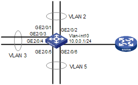
l Create super VLAN 10, and configure its VLAN interface IP address as 10.0.0.1/24.
l Create the sub-VLANs VLAN 2, VLAN 3, and VLAN 5.
l Assign GigabitEthernet 2/0/1 and GigabitEthernet 2/0/2 to VLAN 2, GigabitEthernet 2/0/3 and GigabitEthernet 2/0/4 to VLAN 3, and GigabitEthernet 2/0/5 and GigabitEthernet 2/0/6 to VLAN 5.
l The sub-VLANs are isolated at Layer 2 but connected at Layer 3.
Network diagram
Figure 2-1 Network diagram for super-VLAN configuration
Configuration procedure
# Create VLAN 10, and configure its VLAN interface IP address as 10.0.0.1/24.
<Sysname> system-view
[Sysname] vlan 10
[Sysname-vlan10] interface vlan-interface 10
[Sysname-Vlan-interface10] ip address 10.0.0.1 255.255.255.0
# Enable local proxy ARP.
[Sysname-Vlan-interface10] local-proxy-arp enable
[Sysname-Vlan-interface10] quit
# Create VLAN 2, and assign GigabitEthernet 2/0/1 and GigabitEthernet 2/0/2 to it.
[Sysname] vlan 2
[Sysname-vlan2] port GigabitEthernet 2/0/1 GigabitEthernet 2/0/2
# Create VLAN 3, and assign GigabitEthernet 2/0/3 and GigabitEthernet 2/0/4 to it.
[Sysname-vlan2] quit
[Sysname] vlan 3
[Sysname-vlan3] port GigabitEthernet 2/0/3 GigabitEthernet 2/0/4
# Create VLAN 5, and assign GigabitEthernet 2/0/5 and GigabitEthernet 2/0/6 to it.
[Sysname-vlan3] quit
[Sysname] vlan 5
[Sysname-vlan5] port GigabitEthernet 2/0/5 GigabitEthernet 2/0/6
# Configure VLAN 10 as the super VLAN, and configure VLAN 2, VLAN 3, and VLAN 5 as its sub-VLANs.
[Sysname-vlan5] quit
[Sysname] vlan 10
[Sysname-vlan10] supervlan
[Sysname-vlan10] subvlan 2 3 5
[Sysname-vlan10] quit
[Sysname] quit
Verification
# Display information about VLAN 10 to verify the above configuration.
<Sysname> display supervlan
SuperVLAN ID : 10
SubVLAN ID : 2-3 5
VLAN ID: 10
VLAN Type: static
It is a Super VLAN.
Route Interface: configured
IP Address: 10.0.0.1
Subnet Mask: 255.255.255.0
Description: VLAN 0010
Tagged Ports: none
Untagged Ports: none
VLAN ID: 2
VLAN Type: static
It is a Sub VLAN.
Route Interface: configured
IP Address: 10.0.0.1
Subnet Mask: 255.255.255.0
Description: VLAN 0002
Tagged Ports: none
Untagged Ports:
GigabitEthernet2/0/1 GigabitEthernet2/0/2
VLAN ID: 3
VLAN Type: static
It is a Sub VLAN.
Route Interface: configured
IP Address: 10.0.0.1
Subnet Mask: 255.255.255.0
Description: VLAN 0003
Tagged Ports: none
Untagged Ports:
GigabitEthernet2/0/3 GigabitEthernet2/0/4
VLAN ID: 5
VLAN Type: static
It is a Sub VLAN.
Route Interface: configured
IP Address: 10.0.0.1
Subnet Mask: 255.255.255.0
Description: VLAN 0005
Tagged Ports: none
Untagged Ports:
GigabitEthernet2/0/5 GigabitEthernet2/0/6
When configuring an isolate-user VLAN, go to these sections for information you are interested in:
l Overview
l Configuring Isolate-User-VLAN
l Displaying and Maintaining Isolate-User-VLAN
l Isolate-User-VLAN Configuration Example
Overview
An isolate-user-VLAN adopts a two-tier VLAN structure. In this approach, two types of VLANs, isolate-user-VLAN and secondary VLAN, are configured on the same device.
The following are the characteristics of the isolate-user-VLAN implementation:
l Isolate-user-VLANs are mainly used for upstream data exchange. An isolate-user-VLAN can be associated with multiple secondary VLANs. As the upstream device is aware of only the isolate-user-VLAN but not the secondary VLANs, network configuration is simplified and VLAN resources are saved.
l You can isolate the Layer 2 traffic of different users by assigning the ports connected to them to different secondary VLANs. To enable communication between secondary VLANs associated with the same isolate-user-VLAN, you can enable local proxy ARP on the upstream device to realize Layer 3 communication between the secondary VLANs.
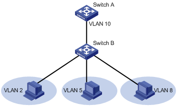
As illustrated in the following figure, the isolate-user-VLAN function is enabled on Switch B. VLAN 10 is the isolate-user-VLAN, and VLAN 2, VLAN 5, and VLAN 8 are secondary VLANs associated with VLAN 10 and are invisible to Switch A.
Figure 3-1 An isolate-user-VLAN example
Configuring Isolate-User-VLAN
Configure the isolate-user-VLAN through the following steps:
1) Configure the isolate-user-VLAN;
2) Configure the secondary VLANs;
3) Assign non-trunk ports to the isolate-user-VLAN and ensure that at least one port takes the isolate-user-VLAN as its default VLAN;
4) Assign non-trunk ports to each secondary VLAN and ensure that at least one port in a secondary VLAN takes the secondary VLAN as its default VLAN;
5) Associate the isolate-user-VLAN with the specified secondary VLANs.
Follow these steps to configure an isolate-user-VLAN:
|
To do... |
Use the command |
Remarks |
|
|
Enter system view |
system-view |
— |
|
|
Create a VLAN and enter VLAN view |
vlan vlan-id |
— |
|
|
Configure the VLAN as an isolate-user-VLAN |
isolate-user-vlan enable |
Required |
|
|
Return to system view |
quit |
— |
|
|
Assign ports to the isolate-user-VLAN and ensure that at least one port takes the isolate-user-VLAN as its default VLAN |
Access port |
Refer to Assigning an Access Port to a VLAN |
Use either approach. |
|
Hybrid port |
Refer to Assigning a Hybrid Port to a VLAN |
||
|
Return to system view |
quit |
— |
|
|
Create secondary VLANs |
vlan { vlan-id1 [ to vlan-id2 ] | all } |
Required |
|
|
Quit to system view |
quit |
— |
|
|
Assign ports to each secondary VLAN and ensure that at least one port in a secondary VLAN takes the secondary VLAN as its default VLAN |
Access port |
Refer to Assigning an Access Port to a VLAN |
Required to choose either |
|
Hybrid port |
Refer to Assigning a Hybrid Port to a VLAN |
||
|
Return to system view |
quit |
— |
|
|
Associate the isolate-user-VLAN with the specified secondary VLANs |
isolate-user-vlan isolate-user-vlan-id secondary secondary-vlan-list |
Required |
|
![]()
After associating an isolate-user-VLAN with the specified secondary VLANs, you cannot add/remove a port to/from each involved VLAN or remove each involved VLAN. To do that, you must cancel the association first.
Displaying and Maintaining Isolate-User-VLAN
|
To do... |
Use the command... |
Remarks |
|
Display the mapping between an isolate-user-VLAN and its secondary VLAN(s) |
display isolate-user-vlan [ isolate-user-vlan-id ] |
Available in any view |
Isolate-User-VLAN Configuration Example
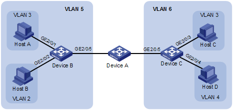
Network requirements
l Connect Device A to downstream devices Device B and Device C;
l Configure VLAN 5 on Device B as an isolate-user-VLAN, assign the uplink port GigabitEthernet 2/0/5 to VLAN 5, and associate VLAN 5 with secondary VLANs VLAN 2 and VLAN 3. Assign GigabitEthernet 2/0/2 to VLAN 2 and GigabitEthernet 2/0/1 to VLAN 3.
l Configure VLAN 6 on Device C as an isolate-user-VLAN, assign the uplink port GigabitEthernet 2/0/5 to VLAN 6, and associate VLAN 6 with secondary VLANs VLAN 3 and VLAN 4. Assign GigabitEthernet 2/0/3 to VLAN 3 and GigabitEthernet 2/0/4 to VLAN 4.
l For Device A, Device B only has VLAN 5 and Device C only has VLAN 6.
Network diagram
Figure 3-2 Network diagram for isolate-user-VLAN configuration
Configuration procedure
The following part provides only the configuration on Device B and Device C.
1) Configure Device B
# Configure the isolate-user-VLAN.
<DeviceB> system-view
[DeviceB] vlan 5
[DeviceB-vlan5] isolate-user-vlan enable
[DeviceB-vlan5] port GigabitEthernet 2/0/5
[DeviceB-vlan5] quit
# Configure the secondary VLANs.
[DeviceB] vlan 3
[DeviceB-vlan3] port GigabitEthernet 2/0/1
[DeviceB-vlan3] quit
[DeviceB] vlan 2
[DeviceB-vlan2] port GigabitEthernet 2/0/2
[DeviceB-vlan2] quit
# Associate the isolate-user-VLAN with the secondary VLANs.
[DeviceB] isolate-user-vlan 5 secondary 2 to 3
2) Configure Device C
# Configure the isolate-user-VLAN.
<DeviceC> system-view
[DeviceC] vlan 6
[DeviceC-vlan6] isolate-user-vlan enable
[DeviceC-vlan6] port GigabitEthernet 2/0/5
[DeviceC-vlan6] quit
# Configure the secondary VLANs.
[DeviceC] vlan 3
[DeviceC-vlan3] port GigabitEthernet 2/0/3
[DeviceC-vlan3] quit
[DeviceC] vlan 4
[DeviceC-vlan4] port GigabitEthernet 2/0/4
# Associate the isolate-user-VLAN with the secondary VLANs.
[DeviceC-vlan4] quit
[DeviceC] isolate-user-vlan 6 secondary 3 to 4
Verification
# Display the isolate-user-VLAN configuration on Device B.
[DeviceB] display isolate-user-vlan
Isolate-user-VLAN VLAN ID : 5
Secondary VLAN ID : 2-3
VLAN ID: 5
VLAN Type: static
Isolate-user-VLAN type : isolate-user-VLAN
Route Interface: not configured
Description: VLAN 0005
Tagged Ports: none
Untagged Ports:
GigabitEthernet2/0/1 GigabitEthernet2/0/2 GigabitEthernet2/0/5
VLAN ID: 2
VLAN Type: static
Isolate-user-VLAN type : secondary
Route Interface: not configured
Description: VLAN 0002
Tagged Ports: none
Untagged Ports:
GigabitEthernet2/0/2 GigabitEthernet2/0/5
VLAN ID: 3
VLAN Type: static
Isolate-user-VLAN type : secondary
Route Interface: not configured
Description: VLAN 0003
Tagged Ports: none
Untagged Ports:
GigabitEthernet2/0/1 GigabitEthernet2/0/5
When configuring a voice VLAN, go to these sections for information you are interested in:
l Overview
l Displaying and Maintaining Voice VLAN
Overview
A voice VLAN is configured specially for voice traffic. After assigning the ports connecting to voice devices to a voice VLAN, you can configure quality of service (QoS) parameters for the voice traffic, thus improving transmission priority and ensuring voice quality.
A device determines whether a received packet is a voice packet by checking its source MAC address. A packet whose source MAC address complies with the voice device Organizationally Unique Identifier (OUI) address is regarded as voice traffic and assigned to the voice VLAN.
You can configure the OUI addresses in advance or use the default OUI addresses. Table 4-1 lists the default OUI address for each vendor’s devices.
Table 4-1 The default OUI addresses of different vendors
|
Number |
OUI address |
Vendor |
|
1 |
0001-e300-0000 |
Siemens phone |
|
2 |
0003-6b00-0000 |
Cisco phone |
|
3 |
0004-0d00-0000 |
Avaya phone |
|
4 |
0060-b900-0000 |
Philips/NEC phone |
|
5 |
00d0-1e00-0000 |
Pingtel phone |
|
6 |
00e0-7500-0000 |
Polycom phone |
|
7 |
00e0-bb00-0000 |
3Com phone |
![]()
l In general, as the first 24 bits of a MAC address (in binary format), an OUI address is a globally unique identifier assigned to a vendor by IEEE. OUI addresses mentioned in this document, however, are different from those in common sense. OUI addresses in this document are used by the system to determine whether a received packet is a voice packet. They are the results of the AND operation of the two arguments mac-address and oui-mask in the voice vlan mac-address command.
l You can remove the default OUI address of a device manually and then add new ones manually.
Voice VLAN Assignment Modes
A port can be assigned to a voice VLAN in one of the following two modes:
l In automatic mode, the system matches the source MAC addresses in the untagged protocol packets sent when the IP phone is powered on against the OUI addresses. If a match is found, the system automatically assigns the port to the voice VLAN, issues ACL rules and configures the packet precedence. You can configure voice VLAN aging time on the device. The system will remove a port from the voice VLAN if no voice packet is received from the port after the aging time expires. Assigning/removing ports to/from a voice VLAN are automatically performed by the system.
l In manual mode, you should assign an IP phone access port to a voice VLAN manually. Then, the system matches the source MAC addresses in the packets against the OUI addresses. If a match is found, the system issues ACL rules and configures the packet precedence. In this mode, assigning/removing ports to/from a voice VLAN are performed manually.
l Both modes forward tagged packets according to their tags.
The following table lists the co-relation between the port voice VLAN mode, the voice traffic type of an IP phone, and the port link type.
Table 4-2 Co-relation
|
Voice VLAN assignment mode |
Voice traffic type |
Port link type |
|
Automatic mode |
Tagged voice traffic |
Access: not supported |
|
Trunk: supported if the default VLAN of the access port exists and is not the voice VLAN and the access port belongs to the voice VLAN |
||
|
Hybrid: supported if the default VLAN of the access port exists and is not the voice VLAN and the traffic of the default VLAN is permitted to pass through the access port tagged |
||
|
Untagged voice traffic |
Access, Trunk, hybrid: not supported |
|
|
Manual mode |
Tagged voice traffic |
Access: not supported |
|
Trunk: supported if the default VLAN of the access port exists and is not the voice VLAN and the access port belongs to the default VLAN |
||
|
Hybrid: supported if the default VLAN of the access port exists and is not the voice VLAN, and the traffic of the default VLAN is permitted to pass through the access port tagged |
||
|
Untagged voice traffic |
Access: supported if the default VLAN of the access port is the voice VLAN |
|
|
Trunk: supported if the default VLAN of the access port is the voice VLAN and that the voice VLAN is permitted to pass through the access port |
||
|
Hybrid port: supported if the default VLAN of the access port is the voice VLAN and is permitted to pass through the access port untagged |
![]()
If an IP phone sends tagged voice traffic and its access port is configured with 802.1X authentication and guest VLAN, you should assign different VLAN IDs for the voice VLAN, the default VLAN of the access port, and the 802.1X guest VLAN.
![]()
l The default VLANs for all ports are VLAN 1. You can configure the default VLAN of a port and configure a port to permit a certain VLAN to pass through with commands. For more information, refer to Port-Based VLAN Configuration.
l Use the display interface command to display the default VLAN of a port and the VLANs permitted to pass through the port.
Security Mode and Normal Mode of Voice VLANs
Voice VLAN-enabled ports can operate in security mode or normal mode based on their inbound packet filtering mechanisms.
l Security mode: only voice packets whose source MAC addresses comply with the recognizable OUI addresses can pass through the voice VLAN-enabled inbound port, while other non-voice packets are dropped, including authentication packets, such as 802.1X authentication packets.
l Normal mode: both voice packets and non-voice packets are allowed to pass through a voice VLAN-enabled inbound port. Voice packets are forwarded according to the voice VLAN forwarding mechanism whereas the non-voice packets are forwarded according to the normal VLAN forwarding mechanism.
It is recommended not to transmit both voice packets and non-voice packets in a voice VLAN. If necessary, please ensure that the voice VLAN security mode is disabled.
Configuring a Voice VLAN
Configuration Prerequisites
Before configuring a VLAN as a voice VLAN, create the VLAN first. Note that you cannot configure VLAN 1 (the system-default VLAN) as a voice VLAN.
Setting a Port to Operate in Automatic Voice VLAN Assignment Mode
Follow these steps to set a port to operate in automatic voice VLAN assignment mode:
|
To do... |
Use the command... |
Remarks |
|
Enter system view |
system-view |
— |
|
Set the voice VLAN aging time |
voice vlan aging minutes |
Optional 1440 minutes by default. The voice VLAN aging time configuration is only applicable on ports in automatic voice VLAN assignment mode. |
|
Enable the voice VLAN security mode |
voice vlan security enable |
Optional Enabled by default. |
|
Add a recognizable OUI address |
voice vlan mac-address oui mask oui-mask [ description text ] |
Optional By default, each voice VLAN has default OUI addresses configured. Refer to Table 4-1 for the default OUI addresses of different vendors. |
|
Enable voice VLAN globally |
voice vlan vlan-id enable |
Required |
|
Enter Ethernet port view |
interface interface-type interface-number |
— |
|
Configure the port to operate in automatic voice VLAN assignment mode |
voice vlan mode auto |
Optional Automatic voice VLAN assignment mode is enabled by default. The voice VLAN assignment modes on different ports are independent of one another. |
|
Enable voice VLAN on the port |
voice vlan enable |
Required Not enabled by default |
![]()
l A protocol-based VLAN on a hybrid port can process only untagged inbound packets, whereas the voice VLAN in automatic mode on a hybrid port can process only tagged voice traffic. Therefore, do not configure a VLAN as both a protocol-based VLAN and a voice VLAN. For more information, refer to Port-Based VLAN Configuration.
l Do not configure the default VLAN of a port in automatic voice VLAN assignment mode as the voice VLAN.
l You need to configure the voice vlan security enable command or the undo voice vlan security enable command before enabling voice VLAN on a device globally. Otherwise, the configurations will not take effect.
Setting a Port to Operate in Manual Voice VLAN Assignment Mode
Follow these steps to set a port to operate in manual voice VLAN assignment mode:
|
To do... |
Use the command... |
Remarks |
|
|
Enter system view |
system-view |
— |
|
|
Enable the voice VLAN security mode |
voice vlan security enable |
Optional Enabled by default. |
|
|
Add a recognizable OUI address |
voice vlan mac-address oui mask oui-mask [ description text ] |
Optional By default, each voice VLAN has default OUI addresses configured. Refer to Table 4-1 for the default OUI addresses of different vendors. |
|
|
Enable voice VLAN globally |
voice vlan vlan-id enable |
Required |
|
|
Enter Ethernet port view |
interface interface-type interface-number |
— |
|
|
Configure the port to operate in manual voice VLAN assignment mode |
undo voice vlan mode auto |
Required Disabled by default |
|
|
Assign the port in manual voice VLAN assignment mode to the voice VLAN |
Access port |
Refer to Assigning an Access Port to a VLAN. |
Use one of the three approaches. After you assign an access port to the voice VLAN, the voice VLAN becomes the default VLAN of the port automatically. |
|
Trunk port |
Refer to Assigning a Trunk Port to a VLAN. |
||
|
Hybrid port |
Refer to Assigning a Hybrid Port to a VLAN. |
||
|
Configure the voice VLAN as the default VLAN of the port |
Trunk port |
Refer to section Assigning a Trunk Port to a VLAN. |
Optional This operation is required for untagged inbound voice traffic and prohibited for tagged inbound voice traffic. |
|
Hybrid port |
Refer to Assigning a Hybrid Port to a VLAN. |
||
|
Enable voice VLAN on the port |
voice vlan enable |
Required |
|
![]()
l There can be only one voice VLAN on a device at a time and this voice VLAN must be a static VLAN that already exists on the device.
l Voice VLAN is mutually exclusive with Link Aggregation Control Protocol (LACP) on a port.
l You need to configure the voice vlan security enable command or the undo voice vlan security enable command before enabling voice VLAN on a device globally. Otherwise, the configurations will not take effect.
l To make voice VLAN take effect on a port that is enabled with voice VLAN and operates in manual voice VLAN assignment mode, you need to assign the port to the voice VLAN manually.
l When the source MAC address of an untagged packet matches an MAC-VLAN entry and an OUI address used in voice VLAN at the same time, the packet will be assigned to the MAC-based VLAN. As a result, the packet will not be able to enter the voice VLAN. Therefore, we recommend you not to configure the OUI addresses of voice packets in MAC-VLAN entries.
Displaying and Maintaining Voice VLAN
|
To do... |
Use the command... |
Remarks |
|
Display the voice VLAN state |
display voice vlan state |
Available in any view |
|
Display the OUI addresses currently supported by system |
display voice vlan oui |
Available in any view |
Voice VLAN Configuration Examples
Automatic Voice VLAN Mode Configuration Example
Network requirement
l Create VLAN 2 and configure it as a voice VLAN with an aging time of 100 minutes.
l The IP phones send tagged voice traffic. Configure GigabitEthernet 2/0/1 as a hybrid port and configure VLAN 6 as its default VLAN.
l The device allows voice packets with an OUI address of 0011-2200-0000 and a mask of ffff-ff00-0000 to be forwarded through the voice VLAN.
Network diagram
Figure 4-1 Network diagram for automatic voice VLAN mode configuration
Configuration procedure
# Create VLAN 2 and VLAN 6.
<DeviceA> system-view
[DeviceA] vlan 2
[DeviceA-vlan2] quit
[DeviceA] vlan 6
[DeviceA-vlan6] quit
# Configure the voice VLAN aging time.
[DeviceA] voice vlan aging 100
# Add a recognizable OUI address 0011-2200-0000.
[DeviceA] voice vlan mac-address 0011-2200-0000 mask ffff-ff00-0000
# Enable voice VLAN globally.
[DeviceA] voice vlan 2 enable
# Configure GigabitEthernet 2/0/1 to operate in automatic voice VLAN mode. (Optional, by default, a port operates in automatic voice VLAN mode.)
[DeviceA] interface gigabitethernet 2/0/1
[DeviceA-GigabitEthernet2/0/1] voice vlan mode auto
# Configure GigabitEthernet 2/0/1 as a hybrid port.
[DeviceA-GigabitEthernet2/0/1] port link-type hybrid
# Configure VLAN 6 as the default VLAN of GigabitEthernet 2/0/1 and configure GigabitEthernet 2/0/1 to allow packets from VLAN 6 to pass through tagged.
[DeviceA-GigabitEthernet2/0/1] port hybrid pvid vlan 6
[DeviceA-GigabitEthernet2/0/1] port hybrid vlan 6 tagged
# Enable voice VLAN on GigabitEthernet 2/0/1.
[DeviceA-GigabitEthernet2/0/1] voice vlan enable
[DeviceA-GigabitEthernet2/0/1] return
Verification
# Display the OUI addresses, OUI address masks, and description strings supported currently.
<DeviceA> display voice vlan oui
Oui Address Mask Description
0001-e300-0000 ffff-ff00-0000 Siemens phone
0003-6b00-0000 ffff-ff00-0000 Cisco phone
0004-0d00-0000 ffff-ff00-0000 Avaya phone
0011-2200-0000 ffff-ff00-0000
0060-b900-0000 ffff-ff00-0000 Philips/NEC phone
00d0-1e00-0000 ffff-ff00-0000 Pingtel phone
00e0-7500-0000 ffff-ff00-0000 Polycom phone
00e0-bb00-0000 ffff-ff00-0000 3com phone
# Display the current voice VLAN state.
<DeviceA> display voice vlan state
Voice VLAN status: ENABLE
Voice VLAN ID: 2
Voice VLAN security mode: Security
Voice VLAN aging time: 100 minutes
Voice VLAN enabled port and its mode:
PORT MODE
--------------------------------
GigabitEthernet2/0/1 AUTO
<DeviceA>
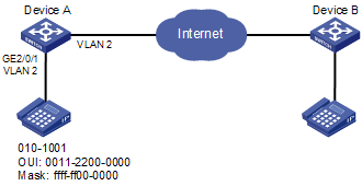
Manual Voice VLAN Mode Configuration Example
Network requirement
l Create VLAN 2 and configure it as a voice VLAN permitting only voice traffic to pass through.
l The IP phones send untagged voice traffic. Configure GigabitEthernet 2/0/1 as a hybrid port.
l Configure GigabitEthernet 2/0/1 to operate in manual voice VLAN mode. Configure GigabitEthernet 2/0/1 to allow only voice traffic with an OUI address of 0011-2200-0000, a mask of ffff-ff00-0000, and a description string test to be forwarded through the voice VLAN.
Network diagram
Figure 4-2 Network diagram for manual voice VLAN mode configuration
Configuration procedure
# Configure the voice VLAN to operate in security mode. (Optional, a voice VLAN operates in security mode by default.)
<DeviceA> system-view
[DeviceA] voice vlan security enable
# Add a recognizable OUI address 0011-2200-0000.
[DeviceA] voice vlan mac-address 0011-2200-0000 mask ffff-ff00-0000 description test
# Create VLAN 2 and configure it as the voice VLAN.
[DeviceA] vlan 2
[DeviceA-vlan2] quit
[DeviceA] voice vlan 2 enable
# Configure GigabitEthernet 2/0/1 to operate in manual voice VLAN mode.
[DeviceA] interface gigabitethernet 2/0/1
[DeviceA-GigabitEthernet2/0/1] undo voice vlan mode auto
# Configure GigabitEthernet 2/0/1 as a hybrid port.
[DeviceA-GigabitEthernet2/0/1]port link-type hybrid
# Configure the voice VLAN (VLAN 2) as the default VLAN of GigabitEthernet 2/0/1 and configure GigabitEthernet 2/0/1 to permit the voice traffic of VLAN 2 to pass through untagged.
[DeviceA-GigabitEthernet2/0/1] port hybrid pvid vlan 2
[DeviceA-GigabitEthernet2/0/1] port hybrid vlan 2 untagged
# Enable voice VLAN on GigabitEthernet 2/0/1.
[DeviceA-GigabitEthernet2/0/1] voice vlan enable
Verification
# Display the OUI addresses, OUI address masks, and description strings supported currently.
<DeviceA> display voice vlan oui
Oui Address Mask Description
0001-e300-0000 ffff-ff00-0000 Siemens phone
0003-6b00-0000 ffff-ff00-0000 Cisco phone
0004-0d00-0000 ffff-ff00-0000 Avaya phone
0011-2200-0000 ffff-ff00-0000 test
0060-b900-0000 ffff-ff00-0000 Philips/NEC phone
00d0-1e00-0000 ffff-ff00-0000 Pingtel phone
00e0-7500-0000 ffff-ff00-0000 Polycom phone
00e0-bb00-0000 ffff-ff00-0000 3com phone
# Display the current voice VLAN state.
<DeviceA> display voice vlan state
Voice VLAN status: ENABLE
Voice VLAN ID: 2
Voice VLAN security mode: Security
Voice VLAN aging time: 100 minutes
Voice VLAN enabled port and its mode:
PORT MODE
--------------------------------
GigabitEthernet2/0/1 MANUAL
