- Table of Contents
-
- 01-Access Volume
- 00-Access Volume Organization
- 01-Ethernet Interface Configuration
- 02-Link Aggregation Configuration
- 03-Port Isolation Configuration
- 04-Service Loopback Group Configuration
- 05-DLDP Configuration
- 06-Smart Link Configuration
- 07-LLDP Configuration
- 08-VLAN Configuration
- 09-GVRP Configuration
- 10-QinQ Configuration
- 11-BPDU Tunneling Configuration
- 12-VLAN Mapping Configuration
- 13-Ethernet OAM Configuration
- 14-Connectivity Fault Detection Configuration
- 15-EPON-OLT Configuration
- 16-MSTP Configuration
- 17-RRPP Configuration
- 18-Mirroring Configuration
- Related Documents
-
| Title | Size | Download |
|---|---|---|
| 11-BPDU Tunneling Configuration | 91.6 KB |
Table of Contents
1 BPDU Tunneling Configuration
Introduction to BPDU Tunneling
Configuring BPDU Transparent Transmission
Configuring Destination Multicast MAC Address for BPDU Tunnel Frames
BPDU Tunneling Configuration Example
When configuring BPDU tunneling, go to these sections for information you are interested in:
l Introduction to BPDU Tunneling
l Configuring BPDU Transparent Transmission
l Configuring Destination Multicast MAC Address for BPDU Tunnel Frames
l BPDU Tunneling Configuration Example
Introduction to BPDU Tunneling
To avoid loops in your network, you can enable the Spanning Tree Protocol (STP) on your device. Here, the term STP is in a broad sense. It includes STP, RSTP, and MSTP. STP calculates the topology of a network by multicasting bridge protocol data units (BPDUs) at Layer 2. As these BPDUs can be received and processed by all STP-enabled devices, this prevents each network from correctly calculating its independent spanning tree.
To allow each network to calculate an independent spanning tree with STP, BPDU tunneling was introduced.
BPDU tunneling delivers the following benefits:
l BPDUs can be transmitted transparently. BPDUs of the same customer network can be broadcast in a specific VLAN across the service provider network, so that the geographically dispersed networks of the same customer can implement consistent spanning tree calculation across the service provider network.
l BPDUs of different customer networks can be confined within different VLANs for transmission on the service provider network. Thus, each customer network can perform independent spanning tree calculation.
As shown in Figure 1-1, the upper part is the service provider network, and the lower part represents the customer networks. The customer networks include network A and network B. Enabling the BPDU tunneling function on the edge devices across the service provider network allows BPDUs of the customer networks to be transparently transmitted in the service provider network, and allows each customer network to implement independent spanning tree calculation, without affecting each other.
Figure 1-1 Network hierarchy of BPDU tunneling
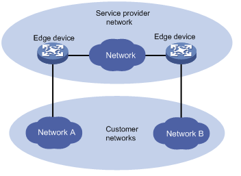
l At the input side of the service provider network, the edge device changes the destination MAC address of a BPDU from a customer network from 0x0180-C200-0000 to a special multicast MAC address, 0x010F-E200-0003 by default. In the service provider’s network, the modified BPDUs are forwarded as data packets in the user VLAN.
l At the output side of the service provider network, the edge device recognizes the BPDU with the destination MAC address of 0x010F-E200-0003 and restores its original destination MAC address 0x0180-C200-0000. Then, the device removes the outer VLAN tag, and sends the BPDU to the destination customer network.
![]()
Make sure, through configuration, that the VLAN tag of the BPDU is carried before enter the service provider network and neither changed nor removed during its transparent transmission in the service provider network; otherwise, the system will fail to transparently transmit the customer network BPDU correctly.
Configuring BPDU Transparent Transmission
Perform the following tasks to configure BPDU transparent transmission:
|
To do... |
Use the command... |
Remarks |
|
|
Enter system view |
system-view |
— |
|
|
Enter Ethernet interface view or port-group view |
Enter Ethernet interface view |
interface interface-type interface-number |
Required Use either command. l Settings made in interface view take effect only on the current port. l Settings made in Layer-2 aggregate interface view take effect only on the Layer-2 aggregate interface. l Settings made in port group view take effect on all ports in the port group. |
|
Enter Layer-2 aggregate interface view |
interface bridge-aggregation interface-number |
||
|
Enter port-group view |
port-group manual port-group-name |
||
|
Disable STP on the port(s) |
stp disable |
Required |
|
|
Enable BPDU tunneling for STP on the port(s) |
bpdu-tunnel dot1q stp |
Required By default, BPDU tunneling for STP is disabled. |
|
Configuring Destination Multicast MAC Address for BPDU Tunnel Frames
By default, the destination multicast MAC address for BPDU tunnel frames is 0x010F-E200-0003. You can modify it to 0x0100-0CCD-CDD0, 0x0100-0CCD-CDD1 or 0x0100-0CCD-CDD2 through the following configuration.
Follow these steps to configure destination multicast MAC address for BPDU tunnel frames:
|
To do… |
Use the command… |
Remarks |
|
Enter system view |
system-view |
— |
|
Configure the destination multicast MAC address for BPDU tunnel frames |
bpdu-tunnel tunnel-dmac mac-address |
Optional 0x010F-E200-0003 by default. |
![]()
For BPDU tunnel frames to be recognized, the destination multicast MAC addresses configured for BPDU tunneling must be the same on the edge devices on the service provider network.
BPDU Tunneling Configuration Example
Network requirements
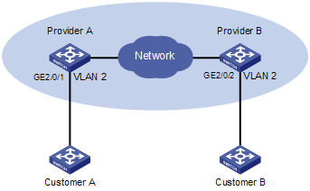
l Customer A and Customer B are customer network edge devices.
l Provider A and Provider B are service provider network edge devices, which are interconnected through configured trunk ports.
The configuration is required to satisfy the following requirements:
l Geographically dispersed customer network access devices Customer A and Customer B can implement consistent spanning tree calculation across the service provider network.
l The destination multicast MAC address configured for BPDU tunnel frames is 0x0100-0CCD-CDD0.
Network diagram
Figure 1-2 Network diagram for BPDU tunneling configuration
Configuration procedure
1) Configuration on Provider A
# Configure the destination multicast MAC address for BPDU tunnel frames as 0x0100-0CCD-CDD0.
<ProviderA> system-view
[ProviderA] bpdu-tunnel tunnel-dmac 0100-0ccd-cdd0
# Configure GigabitEthernet 2/0/1 to transmit packets through VLAN 2.
[ProviderA] vlan 2
[ProviderA-vlan2] quit
[ProviderA] interface GigabitEthernet 2/0/1
[ProviderA-GigabitEthernet2/0/1] port access vlan 2
# Configure GigabitEthernet 2/0/1 to transmit BPDUs transparently.
[ProviderA-GigabitEthernet2/0/1] stp disable
[ProviderA-GigabitEthernet2/0/1] bpdu-tunnel dot1q stp
2) Configuration on Provider B
# Configure the destination multicast MAC address for BPDU tunnel frames as 0x0100-0CCD-CDD0.
<ProviderB> system-view
[ProviderB] bpdu-tunnel tunnel-dmac 0100-0ccd-cdd0
# Configure GigabitEthernet 2/0/2 to transmit packets through VLAN 2.
[ProviderB] vlan 2
[ProviderB-vlan2] quit
[ProviderB] interface GigabitEthernet 2/0/2
[ProviderB-GigabitEthernet2/0/2] port access vlan 2
# Configure GigabitEthernet 2/0/2 to transmit BPDUs transparently.
[ProviderB-GigabitEthernet2/0/2] stp disable
[ProviderB-GigabitEthernet2/0/2] bpdu-tunnel dot1q stp
