- Table of Contents
-
- 01-Access Volume
- 00-Access Volume Organization
- 01-Ethernet Interface Configuration
- 02-Link Aggregation Configuration
- 03-Port Isolation Configuration
- 04-Service Loopback Group Configuration
- 05-DLDP Configuration
- 06-Smart Link Configuration
- 07-LLDP Configuration
- 08-VLAN Configuration
- 09-GVRP Configuration
- 10-QinQ Configuration
- 11-BPDU Tunneling Configuration
- 12-VLAN Mapping Configuration
- 13-Ethernet OAM Configuration
- 14-Connectivity Fault Detection Configuration
- 15-EPON-OLT Configuration
- 16-MSTP Configuration
- 17-RRPP Configuration
- 18-Mirroring Configuration
- Related Documents
-
| Title | Size | Download |
|---|---|---|
| 09-GVRP Configuration | 125.31 KB |
The GARP VLAN Registration Protocol (GVRP) is a GARP application. It functions based on the operating mechanism of GARP to maintain and propagate dynamic VLAN registration information for the GVRP devices on the network.
When configuring GVRP, go to these sections for information you are interested in:
l Displaying and Maintaining GVRP
Introduction to GVRP
GARP
The Generic Attribute Registration Protocol (GARP) provides a mechanism that allows participants in a GARP application to distribute, propagate, and register with other participants in a LAN the attributes specific to the GARP application, such as the VLAN or multicast address attribute.
GARP itself does not exist on a device as an entity. GARP-compliant participants are known as GARP applications. One example is GVRP. When a GARP participant is present on a port on your device, the port is regarded as a GARP participant.
GARP messages and timers
1) GARP messages
A GARP participant exchanges information with other GARP participants by sending the following three types of messages:
l Join messages to register with other entities its attributes, the attributes received from other GARP application entities, and the attributes manually configured on it.
l Leave messages to have its attributes deregistered on other devices. A GARP participant also sends Leave messages when it receives Leave messages from other GARP participants or when attributes are manually deregistered on it.
l LeaveAll messages to deregister all the attributes so that all GARP participants can re-register all attributes with each other. A LeaveAll message is sent upon expiration of a LeaveAll timer, which starts upon the startup of a GARP application entity.
Join messages, Leave messages, and LeaveAll message make sure the reregistration and deregistration of GARP attributes are performed in an orderly way.
Through message exchange, all attribute information that needs registration propagates to all GARP participants on the LAN.
2) GARP timers
GARP uses the following four timers to set the interval for sending GARP messages:
l Hold timer –– When a GARP application entity receives the first registration request, it starts a hold timer and collects succeeding requests. When the timer expires, the entity sends all these requests in one Join message. This helps you save bandwidth.
l Join timer –– A GARP participant sends each Join message at most twice for reliability sake and uses a join timer to set the sending interval. If the first Join message has not been acknowledged before the Join timer expires, the GARP participant sends the second Join message.
l Leave timer –– Starts upon receipt of a Leave message sent for deregistering some attribute information. If no Join message has been received before this timer expires, the GARP participant removes the attribute information as requested.
l LeaveAll timer –– Starts when a GARP participant starts. When this timer expires, the entity sends a LeaveAll message so that other participants can re-register its attribute information. Then, a LeaveAll timer starts again.
![]()
l The settings of GARP timers apply to all GARP applications, such as GVRP, on a LAN.
l Unlike other three timers, which are set on a port basis, the LeaveAll timer is set in system view and takes effect globally.
l A GARP participant may send LeaveAll messages at the interval set by its LeaveAll timer or the LeaveAll timer on another device on the network, whichever is smaller. This is because each time a device on the network receives a LeaveAll message it resets its LeaveAll timer.
Operating mechanism of GARP
The GARP mechanism allows the configuration of a GARP participant to propagate throughout a LAN quickly. In GARP, a GARP participant registers or deregisters its attributes with other participants by making or withdrawing declarations of attributes and at the same time, based on received declarations or withdrawals, handles attributes of other participants. When a port receives an attribute declaration, it registers the attribute; when a port receives an attribute withdrawal, it deregisters the attribute.
GARP participants send protocol data units (PDU) with a particular multicast MAC address as destination. Based on this address, a device can identify to which GVRP application (GVRP for example) a GARP PDU should be delivered.
GARP message format
The following figure illustrates the GARP message format.
Figure 1-1 GARP message format
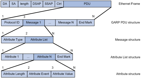
Table 1-1 describes the GARP message fields.
Table 1-1 Description on the GARP message fields
|
Field |
Description |
Value |
|
Protocol ID |
Protocol identifier for GARP |
1 |
|
Message |
One or multiple messages, each containing an attribute type and an attribute list |
–– |
|
Attribute Type |
Defined by the concerned GARP application |
0x01 for GVRP, indicating the VLAN ID attribute |
|
Attribute List |
Contains one or multiple attributes |
–– |
|
Attribute |
Consists of an Attribute Length, an Attribute Event, and an Attribute Value |
–– |
|
Attribute Length |
Number of octets occupied by an attribute, inclusive of the attribute length field |
2 to 255 (in bytes) |
|
Attribute Event |
Event described by the attribute |
0: LeaveAll event 1: JoinEmpty event 2: JoinIn event 3: LeaveEmpty event 4: LeaveIn event 5: Empty event |
|
Attribute Value |
Attribute value |
VLAN ID for GVRP If the Attribute Event is LeaveAll, Attribute Value is omitted. |
|
End Mark |
Indicates the end of a GARP PDU |
0x00 |
GVRP
GVRP enables a device to propagate local VLAN registration information to other participant devices and dynamically update the VLAN registration information from other devices to its local database about active VLAN members and through which port they can be reached. It thus ensures that all GVRP participants on a bridged LAN maintain the same VLAN registration information. The VLAN registration information propagated by GVRP includes both manually configured local static entries and dynamic entries from other devices.
GVRP provides the following three registration types on a port:
l Normal –– Enables the port to dynamically register and deregister VLANs, and to propagate both dynamic and static VLAN information.
l Forbidden –– Disables the port to dynamically register and deregister VLANs and to propagate VLAN information except information about VLAN 1. A trunk port with forbidden registration type thus allows only VLAN 1 to pass through even though it is configured to carry all VLANs.
Protocols and Standards
GVRP is described in IEEE 802.1Q.
Configuring GVRP
![]()
GVRP can only be configured on trunk ports.
Configuring GVRP includes Configuring GVRP Functions and Configuring GARP Timers.
Configuring GVRP Functions
Before enabling GVRP on a port, you must enable GVRP globally.
Follow these steps to configure GVRP functions on a trunk port:
|
To do… |
Use the command… |
||
|
Enter system view |
system-view |
–– |
|
|
Enable GVRP globally |
gvrp |
Required Globally disabled by default |
|
|
Enter Ethernet interface view or port-group view |
Enter Ethernet interface view |
interface interface-type interface-number |
Required Use either command. l In Ethernet interface view, the subsequent configurations apply to the current port. l In port group view, the subsequent configurations apply to all ports in the port group. l In Layer-2 aggregate interface view, the subsequent configurations apply to the Layer-2 aggregate interface and all its member ports. |
|
Enter Layer-2 aggregate interface view |
interface bridge-aggregation interface-number |
||
|
Enter port-group view |
port-group manual port-group-name |
||
|
Enable GVRP on the port |
gvrp |
Required Disabled by default |
|
|
Configure the GVRP registration mode on the port |
gvrp registration { fixed | forbidden | normal } |
Optional The default is normal. |
|
![]()
l GVRP is mutually exclusive with service loopback.
l In an MSTP network, GVRP can run on only the CIST. In addition, blocked ports on the CIST cannot receive/send GVRP packets.
l If both GVRP and remote port mirroring are used, GVRP may register the remote probe VLAN to unexpected ports, resulting in undesired duplicates to be received by the monitor port. For more information about port mirroring, refer to Port Mirroring Configuration in the Access Volume.
l Enabling GVRP on a Layer 2 aggregate interface enables both the aggregate interface and all selected member ports in the corresponding link aggregation group to participate in dynamic VLAN registration and deregistration. In addition, the GVRP configuration made on a link aggregation member port can take effect only after the port is removed from the group. For more information about link aggregation, refer to Link Aggregation Configuration in the Access Volume.
l On a GVRP-enabled trunk port, you need to configure the port trunk permit vlan all command on the port to ensure that the traffic of all dynamically registered VLANs can pass through the port.
Configuring GARP Timers
Among the four GARP timers, the LeaveAll timer is configured in system view and takes effect on all ports, while the other three are configured on a port basis.
Follow these steps to configure GARP timers:
|
To do… |
Use the command… |
Remarks |
|
|
Enter system view |
system-view |
–– |
|
|
Configure the GARP LeaveAll timer |
garp timer leaveall timer-value |
Optional The default is 1000 centiseconds. |
|
|
Enter Ethernet interface view or port-group view |
Enter Ethernet interface view |
interface interface-type interface-number |
Required Use either command. l In Ethernet interface view, the subsequent configurations apply to the current port. l In port group view, the subsequent configurations apply to all ports in the port group. l In Layer-2 aggregate interface view, the subsequent configurations apply to the Layer-2 aggregate interface and all its member ports. |
|
Enter Layer-2 aggregate interface view |
interface bridge-aggregation interface-number |
||
|
Enter port-group view |
port-group manual port-group-name |
||
|
Configure the hold timer, join timer, and leave timer |
garp timer { hold | join | leave } timer-value |
Optional The default is 10 centiseconds for the hold timer, 20 centiseconds for the join timer, and 60 centiseconds for the leave timer. |
|
When configuring GARP timers, note that their values are dependent on each other and must be a multiple of five centiseconds. If the value range for a timer is not desired, you may change it by tuning the value of another related timer as shown in the following table:
Table 1-2 Dependencies of GARP timers
|
Timer |
Lower limit |
Upper limit |
|
Hold |
10 centiseconds |
Not greater than half of the join timer setting |
|
Join |
Not less than two times the hold timer setting |
Less than half of the leave timer setting |
|
Leave |
Greater than two times the join timer setting |
Less than the LeaveAll timer setting |
|
LeaveAll |
Greater than the leave timer setting |
32765 centiseconds |
![]()
The GVRP configuration made on a link aggregation member port can take effect only after the port is removed from the group. For more information about link aggregation, refer to Link Aggregation Configuration in the Access Volume.
Displaying and Maintaining GVRP
|
To do… |
Use the command… |
Remarks |
|
Display statistics about GARP |
display garp statistics [ interface interface-list ] |
Available in any view |
|
Display GARP timers for specified or all ports |
display garp timer [ interface interface-list ] |
Available in any view |
|
Display the local VLAN information maintained by GVRP |
display gvrp local-vlan interface interface-type interface-number |
Available in any view |
|
Display the current GVRP state |
display gvrp state interface interface-type interface-number vlan vlan-id |
Available in any view |
|
Display statistics about GVRP |
display gvrp statistics [ interface interface-list ] |
Available in any view |
|
Display the global GVRP state |
display gvrp status |
Available in any view |
|
Display the information about dynamic VLAN operations performed on a port |
display gvrp vlan-operation interface interface-type interface-number |
Available in any view |
|
Clear the GARP statistics |
reset garp statistics [ interface interface-list ] |
Available in user view |
GVRP Configuration Examples
GVRP Configuration Example I
Network requirements
Configure GVRP for dynamic VLAN information registration and update among devices, adopting the normal registration mode on ports.
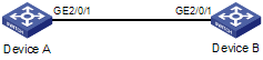
Network diagram
Figure 1-2 Network diagram for GVRP configuration
Configuration procedure
1) Configure Device A
# Enable GVRP globally.
<DeviceA> system-view
[DeviceA] gvrp
# Configure port GigabitEthernet 2/0/1 as a trunk port, allowing all VLANs to pass through.
[DeviceA] interface GigabitEthernet 2/0/1
[DeviceA-GigabitEthernet2/0/1] port link-type trunk
[DeviceA-GigabitEthernet2/0/1] port trunk permit vlan all
# Enable GVRP on GigabitEthernet 2/0/1, the trunk port.
[DeviceA-GigabitEthernet2/0/1] gvrp
[DeviceA-GigabitEthernet2/0/1] quit
# Create VLAN 2 (a static VLAN).
[DeviceA] vlan 2
2) Configure Device B
# Enable GVRP globally.
<DeviceB> system-view
[DeviceB] gvrp
# Configure port GigabitEthernet 2/0/1 as a trunk port, allowing all VLANs to pass through.
[DeviceB] interface GigabitEthernet 2/0/1
[DeviceB-GigabitEthernet2/0/1] port link-type trunk
[DeviceB-GigabitEthernet2/0/1] port trunk permit vlan all
# Enable GVRP on GigabitEthernet 2/0/1, the trunk port.
[DeviceB-GigabitEthernet2/0/1] gvrp
[DeviceB-GigabitEthernet2/0/1] quit
# Create VLAN 3 (a static VLAN).
[DeviceB] vlan 3
3) Verify the configuration
# Display dynamic VLAN information on Device A.
[DeviceA] display vlan dynamic
Now, the following dynamic VLAN exist(s):
3
# Display dynamic VLAN information on Device B.
[DeviceB] display vlan dynamic
Now, the following dynamic VLAN exist(s):
2
GVRP Configuration Example II
Network requirements
Configure GVRP for dynamic VLAN information registration and update among devices. Specify fixed GVRP registration on Device A and normal GVRP registration on Device B.
Network diagram
Figure 1-3 Network diagram for GVRP configuration
Configuration procedure
1) Configure Device A
# Enable GVRP globally.
<DeviceA> system-view
[DeviceA] gvrp
# Configure port GigabitEthernet 2/0/1 as a trunk port, allowing all VLANs to pass through.
[DeviceA] interface GigabitEthernet 2/0/1
[DeviceA-GigabitEthernet2/0/1] port link-type trunk
[DeviceA-GigabitEthernet2/0/1] port trunk permit vlan all
# Enable GVRP on GigabitEthernet 2/0/1.
[DeviceA-GigabitEthernet2/0/1] gvrp
# Set the GVRP registration type to fixed on the port.
[DeviceA-GigabitEthernet2/0/1] gvrp registration fixed
[DeviceA-GigabitEthernet2/0/1] quit
# Create VLAN 2 (a static VLAN).
[DeviceA] vlan 2
2) Configure Device B
# Enable GVRP globally.
<DeviceB> system-view
[DeviceB] gvrp
# Configure port GigabitEthernet 2/0/1 as a trunk port, allowing all VLANs to pass through.
[DeviceB] interface GigabitEthernet 2/0/1
[DeviceB-GigabitEthernet2/0/1] port link-type trunk
[DeviceB-GigabitEthernet2/0/1] port trunk permit vlan all
# Enable GVRP on GigabitEthernet 2/0/1.
[DeviceB-GigabitEthernet2/0/1] gvrp
[DeviceB-GigabitEthernet2/0/1] quit
# Create VLAN 3 (a static VLAN).
[Sysname] vlan 3
3) Verify the configuration
# Display dynamic VLAN information on Device A.
[DeviceA] display vlan dynamic
No dynamic vlans exist!
# Display dynamic VLAN information on Device B.
[DeviceB] display vlan dynamic
Now, the following dynamic VLAN exist(s):
2
GVRP Configuration Example III
Network requirements
To prevent dynamic VLAN information registration and update among devices, set the GVRP registration mode to forbidden on Device A and normal on Device B.
Network diagram
Figure 1-4 Network diagram for GVRP configuration
Configuration procedure
1) Configure Device A
# Enable GVRP globally.
<DeviceA> system-view
[DeviceA] gvrp
# Configure port GigabitEthernet 2/0/1 as a trunk port, allowing all VLANs to pass through.
[DeviceA] interface GigabitEthernet 2/0/1
[DeviceA-GigabitEthernet2/0/1] port link-type trunk
[DeviceA-GigabitEthernet2/0/1] port trunk permit vlan all
# Enable GVRP on GigabitEthernet 2/0/1.
[DeviceA-GigabitEthernet2/0/1] gvrp
# Set the GVRP registration type to forbidden on the port.
[DeviceA-GigabitEthernet2/0/1] gvrp registration forbidden
[DeviceA-GigabitEthernet2/0/1] quit
# Create VLAN 2 (a static VLAN).
[DeviceA] vlan 2
2) Configure Device B
# Enable GVRP globally.
<DeviceB> system-view
[DeviceB] gvrp
# Configure port GigabitEthernet 2/0/1 as a trunk port, allowing all VLANs to pass through.
[DeviceB] interface GigabitEthernet 2/0/1
[DeviceB-GigabitEthernet2/0/1] port link-type trunk
[DeviceB-GigabitEthernet2/0/1] port trunk permit vlan all
# Enable GVRP on GigabitEthernet 2/0/1.
[DeviceB-GigabitEthernet2/0/1] gvrp
[DeviceB-GigabitEthernet2/0/1] quit
# Create VLAN 3 (a static VLAN).
[DeviceB] vlan 3
3) Verify the configuration
# Display dynamic VLAN information on Device A.
[DeviceA] display vlan dynamic
No dynamic vlans exist!
# Display dynamic VLAN information on Device B.
[DeviceB] display vlan dynamic
No dynamic vlans exist!
