- Table of Contents
-
- 01-Access Volume
- 00-Access Volume Organization
- 01-Ethernet Interface Configuration
- 02-Link Aggregation Configuration
- 03-Port Isolation Configuration
- 04-Service Loopback Group Configuration
- 05-DLDP Configuration
- 06-Smart Link Configuration
- 07-LLDP Configuration
- 08-VLAN Configuration
- 09-GVRP Configuration
- 10-QinQ Configuration
- 11-BPDU Tunneling Configuration
- 12-VLAN Mapping Configuration
- 13-Ethernet OAM Configuration
- 14-Connectivity Fault Detection Configuration
- 15-EPON-OLT Configuration
- 16-MSTP Configuration
- 17-RRPP Configuration
- 18-Mirroring Configuration
- Related Documents
-
| Title | Size | Download |
|---|---|---|
| 12-VLAN Mapping Configuration | 329.58 KB |
Table of Contents
One-to-One VLAN Mapping and Many-to-One VLAN Mapping
One-to-Two VLAN Mapping and Two-to-Two VLAN Mapping
Basic Concepts of VLAN Mapping
How VLAN Mapping Is Implemented
VLAN Mapping Configuration Task List
Configuring One-to-One VLAN Mapping
Configuring One-to-One VLAN Mapping
Configuring Many-to-One VLAN Mapping
Configuring Many-to-One VLAN Mapping
Configuring One-to-Two VLAN Mapping
Configuring Two-to-Two VLAN Mapping
VLAN Mapping Configuration Examples
One-to-One/Many-to-One VLAN Mapping Configuration Example
One-to-Two/Two-to-Two VLAN Mapping Configuration Example
When configuring VLAN mapping, go to these sections for information you are interested in:
l VLAN Mapping Configuration Task List
l Configuring One-to-One VLAN Mapping
l Configuring Many-to-One VLAN Mapping
l Configuring One-to-Two VLAN Mapping
l Configuring Two-to-Two VLAN Mapping
l VLAN Mapping Configuration Examples
VLAN Mapping Overview
VLAN mapping maps the customer VLANs (CVLANs) to service-provider VLANs (SVLANs). Types of VLAN mapping include:
l One-to-one VLAN mapping that maps the CVLAN ID in the VLAN tag to the SVLAN ID.
l Many-to-one VLAN mapping that maps the CVLAN IDs in the VLAN tags of traffic of more than two VLANs to the same SVLAN ID.
l One-to-two VLAN mapping that maps traffic with the inner VLAN ID to the inner VLAN ID and the SVLAN ID.
l Two-to-two VLAN mapping that maps traffic with outer and inner VLAN IDs to the service-provider outer and the inner VLAN IDs.
![]()
Only SC boards support these four types of VLAN mappings. The other boards support only one-to-one VLAN mapping. For detailed information on board types, refer to the corresponding installation manual.
The following sections present the scenario to which these VLAN mapping types apply.
One-to-One VLAN Mapping and Many-to-One VLAN Mapping
One-to-one VLAN mapping and many-to-one VLAN mapping are mainly applied in campus networks as shown in Figure 1-1.
Figure 1-1 Scenario for one-to-one/multiple-to-one VLAN mapping
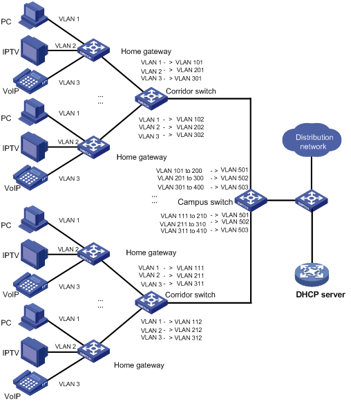
In such a network, different VLANs are used for transmitting different services (PC, IPTV, and VoIP for example) of a home user. Furthermore, to differentiate home users that are using the same service, you need to perform one-to-one VLAN mapping to map the service traffic to different VLANs by user on the corridor switches. However, an access device on the distribution layer is likely unable to support the number of VLANs required for this type of VLAN mapping.
To reduce the number of VLANs required on the edge device at the distribution layer, you can adopt many-to-one VLAN mapping. This type of VLAN mapping maps the VLANs carrying the same service of different users to the same VLAN while isolating the service traffic of different users.
One-to-Two VLAN Mapping and Two-to-Two VLAN Mapping
One-to-two VLAN mapping and two-to-two VLAN mapping are mainly applied in networking environments as shown in Figure 1-2.
Figure 1-2 Scenario for one-to-two/two-to-two VLAN mapping
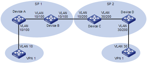
In Figure 1-2, two VPN 1 users located in different regions communicate with each other across two service provider (SP) networks: SP 1 and SP 2.
1) When the packet tagged with VLAN 10 arrives at the edge of the SP 1 network, Device A tags the packet with VLAN 100, the VLAN ID assigned to the VPN 1 user in SP 1. The packet thus becomes double-tagged and this single-tag to double-tag translation process is called one-to-two VLAN mapping. One-to-two VLAN mapping enables VPN users to plan their own customer VLAN IDs independent of SP network VLAN IDs, thus saving the VLAN resources of SPs.
2) When the double-tagged packet enters the SP 2 network, Device C replaces the outer VLAN tag (VLAN 100) with VLAN 200, the VLAN ID assigned by SP 2 to the VPN 1 user. For the packet to reach the VPN 1 user in VLAN 30, Device C replaces the inner tag (VLAN 10) of the packet with VLAN 30. This double-tag to double-tag replacement is called two-to-two VLAN mapping.
Basic Concepts of VLAN Mapping
Before you configure VLAN mappings, be aware of the following concepts, which will be used throughout this document.
l Uplink traffic: Traffic transmitted from a home user network to a distribution network or from a user network to an SP network.
l Downlink traffic: Traffic transmitted from a distribution network to a home user network or from an SP network to a user network.
l Uplink port: A port transmitting uplink traffic and receiving downlink traffic.
l Downlink port: A port transmitting downlink traffic and receiving uplink traffic.
l Uplink policy: A QoS policy containing VLAN mappings for uplink traffic.
l Downlink policy: A QoS policy containing VLAN mappings for downlink traffic.
How VLAN Mapping Is Implemented
This section describes how VLAN mapping is implemented on your device.
One-to-one VLAN mapping
|
On the downlink port |
|||
|
For uplink traffic |
For downlink traffic |
||
|
Do… |
Based on… |
Do… |
Based on… |
|
Replace the customer VLAN (CVLAN) with the service provider VLAN (SVLAN) |
Uplink policy in the inbound direction |
Replace the SVLAN with the original CVLAN |
Downlink policy in the outbound direction |
Many-to-one VLAN mapping
|
On the downlink port |
On the uplink port |
||
|
For uplink traffic |
For downlink traffic |
||
|
Do... |
Based on… |
Do... |
Based on… |
|
Map all specified customer VLANs (CVLAN) to one service provider VLAN (SVLAN) |
Uplink policy in the inbound direction |
Replace the SVLAN with the original CVLAN |
DHCP snooping address table, which contains mappings of the SVLAN, IP address, MAC address, and CVLAN for DHCP clients |
One-to-two VLAN mapping
|
On the downlink port |
|||
|
For uplink traffic |
For downlink traffic |
||
|
Do... |
Based on… |
Do... |
Based on… |
|
Tag the CVLAN-tagged traffic with the SVLAN |
Uplink policy in the inbound direction |
Forward traffic with the outer VLAN tag (the SVLAN) removed |
You need to configure the downlink port as a hybrid port to forward SVLAN frames with the outer VLAN tag removed. |
Two-to-two VLAN mapping
![]()
In two-to-two VLAN mapping, the outer VLAN and the inner VLAN carried in a double-tagged uplink frame received at the downlink port on the edge device of an SP network are called the original SVLAN and CVLAN, and the VLANs that the edge device substitutes for the original SVLAN and CVLAN are called the new SVLAN and CVLAN.
|
On the downlink port |
On the uplink port |
||||
|
For uplink traffic |
For downlink traffic |
For uplink traffic |
|||
|
Do... |
Based on… |
Do... |
Based on… |
Do... |
Based on… |
|
Replace the original SVLAN with the new SVLAN |
Uplink policy in the inbound direction |
Replace the new SVLAN and CVLAN with the original SVLAN and CVLAN |
Downlink policy in the outbound direction |
Replace the original CVLAN with the new CVLAN |
Uplink policy in the outbound direction |
![]()
l For information about DHCP snooping, refer to DHCP Configuration in the IP Services Volume.
l For information about QoS policies, refer to QoS Configuration in the QoS Volume.
VLAN Mapping Configuration Task List
You need to configure VLAN mapping on your device depending on its position in the network.
Complete the following tasks to configure VLAN mapping:
|
Task |
Remarks |
|
Optional Perform this configuration on the corridor switches shown in Figure 1-1 |
|
|
Optional Perform this configuration on the campus switches shown in Figure 1-1 |
|
|
Optional Perform this configuration on the edge devices from which user traffic enters the SP network. Examples are Device A and Device D in Figure 1-2. |
|
|
Optional Perform this configuration on an edge device connecting two SP networks. An example is Device C in the SP 2 network in Figure 1-2. |
For VLAN mapping to work, you are required to do the following in addition to configuring QoS policies:
l Enable ARP detection to send ARP packets to the CPU to allow modification of the VLAN attributes carried in the packets, which is impossible with the normal ARP packet processing procedure. For information about ARP detection, refer to ARP Configuration in the IP Services Volume.
l Enable the dynamic address binding support of IP Source Guard to filter packets received on a port based on the source IP address and MAC address bindings created dynamically to prevent illegal packets from passing through the port. For information about this feature, refer to IP Source Guard Configuration in the Security Volume.
l To save system resources, disable user bindings recording on the DHCP snooping trusted ports that forward DHCP packets. For information about this feature, refer to DHCP Configuration in the IP Services Volume.
Configuring One-to-One VLAN Mapping
Perform one-to-one VLAN mapping on the corridor switches shown in Figure 1-1 to use VLANs to isolate different services of different users.
Configuring One-to-One VLAN Mapping
Configuration prerequisites
The CVLAN-to-SVLAN mappings have been planned.
Configuration procedure
Follow these steps to configure a one-to-one VLAN mapping:
|
To do... |
Use the command... |
Remarks |
|
|
Enter system view |
system-view |
— |
|
|
Create a CVLAN and a SVLAN |
Create a VLAN |
vlan vlan-id |
Required By default, only the default VLAN (VLAN 1) exists. Repeat these steps for all CVLANs and SVLANs involved in VLAN mapping. |
|
Exit to system view |
quit |
||
|
Refer to Table 1-1 |
Required |
||
|
Configure a downlink policy to map the SVLAN to the original CVLAN |
Refer to Table 1-2 |
Required |
|
|
Enter interface view of the downlink port |
interface interface-type interface-number |
— |
|
|
Set the link type of the downlink port to trunk |
port link-type trunk |
Required |
|
|
Configure the downlink port to permit the specified CVLANs and SVLANs or all VLANs to pass through |
port trunk permit vlan { vlan-id-list | all } |
Required By default, a trunk port permits only VLAN 1 to pass through. |
|
|
Enable basic QinQ on the port |
qing enable |
Required |
|
|
Apply the uplink policy to the inbound direction of the downlink port |
qos apply policy policy-name inbound |
Required |
|
|
Apply the downlink policy to the outbound direction of the downlink port |
qos apply policy policy-name outbound |
Required |
|
|
Exit to system view |
quit |
— |
|
|
Enter the interface view of the uplink port |
interface interface-type interface-number |
— |
|
|
Set the link type of the uplink port to trunk |
port link-type trunk |
Required |
|
|
Configure the uplink port to permit the specified SVLANs to pass through |
port trunk permit vlan { vlan-id-list | all } |
Required By default, a trunk port permits only VLAN 1 to pass through. |
|
Table 1-1 Configure an uplink policy
|
To do... |
Use the command... |
Remarks |
|
Enter system view |
system-view |
— |
|
Create a class and enter class view |
traffic classifier tcl-name [ operator { and | or } ] |
Required |
|
Specify the CVLAN for the VLAN mapping |
if-match customer-vlan-id vlan-id-value |
Required |
|
Exit to system view |
quit |
— |
|
Create a traffic behavior and enter traffic behavior view |
traffic behavior behavior-name |
Required |
|
Specify the SVLAN for the VLAN mapping |
remark service-vlan-id vlan-id-value |
Required |
|
Exit to system view |
quit |
— |
|
Create a QoS policy and enter QoS policy view |
qos policy policy-name |
Required |
|
Map the CVLAN to the SVLAN by associating the traffic class with the traffic behavior |
classifier tcl-name behavior behavior-name |
Required |
|
Exit to system view |
quit |
— |
Table 1-2 Configure a downlink policy
|
To do... |
Use the command... |
Remarks |
|
Enter system view |
system-view |
— |
|
Create a class and enter class view |
traffic classifier tcl-name [ operator { and | or } ] |
Required |
|
Specify the SVLAN for the VLAN mapping |
if-match service-vlan-id vlan-id-value |
Required |
|
Exit to system view |
quit |
— |
|
Create a traffic behavior and enter traffic behavior view |
traffic behavior behavior-name |
Required |
|
Specify the CVLAN for the VLAN mapping |
remark customer-vlan-id vlan-id-value |
Required |
|
Exit to system view |
quit |
— |
|
Create a QoS policy and enter QoS policy view |
qos policy policy-name |
Required |
|
Map the SVLAN to the CVLAN by associating the traffic class with the traffic behavior |
classifier tcl-name behavior behavior-name |
Required |
|
Exit to system view |
quit |
— |
Configuring Many-to-One VLAN Mapping
Configuring Many-to-One VLAN Mapping
Configuration prerequisites
l All service terminals of home users are using DHCP for obtaining an IP address. For how to get an IP address through DHCP, refer to DHCP Configuration in the IP Services Volume.
l The CVLAN-to-SVLAN mappings have been planned.
Configuration procedure
Follow these steps to configure a many-to-one VLAN mapping:
|
To do... |
Use the command... |
Remarks |
|
|
Enter system view |
system-view |
— |
|
|
Enable DHCP snooping |
dhcp-snooping |
Required Disabled by default. |
|
|
Enable ARP detection on the CVLANs and the SVLAN for the VLAN mapping |
Create a VLAN and enter VLAN view |
vlan vlan-id |
Required Disabled by default. Repeat these steps for all CVLANs and the SVLAN that the VLAN mapping involves. |
|
Enable ARP detection |
arp detection enable |
||
|
Exit to system view |
quit |
||
|
Configure an uplink policy to map the CVLANs to the same SVLAN |
Refer to Table 1-3. |
Required |
|
|
Enter the interface view of the downlink port |
interface interface-type interface-number |
— |
|
|
Set the link type of the downlink port to trunk |
port link-type trunk |
Required |
|
|
Configure the downlink port to permit the specified CVLANs and SVLANs to pass through |
port trunk permit vlan { vlan-id-list | all } |
Required By default, a trunk port permits only VLAN 1 to pass through. |
|
|
Enable customer side QinQ |
qinq enable downlink |
Required Disabled by default. |
|
|
Apply the uplink policy to the downlink port in the inbound direction |
qos apply policy policy-name inbound |
Required |
|
|
Exit to system view |
quit |
— |
|
|
Enter the interface view of the uplink port |
interface interface-type interface-number |
— |
|
|
Configure the uplink port as a DHCP snooping trusted port |
dhcp-snooping trust |
Required By default, all ports with DHCP snooping enabled are DHCP snooping untrusted ports. |
|
|
Configure the uplink port as an ARP trusted port |
arp detection trust |
Required By default, all ports are ARP untrusted ports. |
|
|
Set the link type of the uplink port to trunk |
port link-type trunk |
Required |
|
|
Configure the uplink port to permit the specified SVLANs to pass through |
port trunk permit vlan { vlan-id-list | all } |
Required By default, a trunk port permits only VLAN 1 to pass through. |
|
|
Enable service provider side QinQ |
qinq enable uplink |
Required Disabled by default. |
|
Table 1-3 Configure an uplink policy
|
To do... |
Use the command... |
Remarks |
|
Enter system view |
system-view |
— |
|
Create a class and enter class view |
traffic classifier tcl-name operator or |
Required |
|
Specify the CVLANs for the VLAN mapping |
if-match customer-vlan-id { vlan-id-list | vlan-id1 to vlan-id2 } |
Required |
|
Exit to system view |
quit |
— |
|
Create a traffic behavior and enter traffic behavior view |
traffic behavior behavior-name |
Required |
|
Specify the SVLAN for the VLAN mapping |
remark service-vlan-id vlan-id-value |
Required |
|
Exit to system view |
quit |
— |
|
Create a QoS policy and enter QoS policy view |
qos policy policy-name |
Required |
|
Map the CVLANs to the SVLAN by associating the traffic class with the traffic behavior |
classifier tcl-name behavior behavior-name mode dot1q-tag-manipulation |
Required |
|
Exit to system view |
quit |
— |
![]()
l To guard against attacks, you are recommended to enable ARP detection on each CVLAN.
l Before applying a QoS policy to the downlink port, enable customer-side QinQ on the port; before disabling customer-side QinQ on the downlink port, remove the QoS policy.
l To change a VLAN mapping, you must first use the reset dhcp-snooping command to clear the corresponding DHCP snooping address binding entry (refer to DHCP Commands in the IP Services Volume) or disable the dynamic address binding function of IP Source Guard on the downlink port and then enable dynamic address binding again (refer to IP Source Guard Commands in the Security Volume).
l When configuring many-to-one VLAN mapping, you cannot create VLAN interfaces for the involved SVLANs and CVLANs on the switch.
Configuring One-to-Two VLAN Mapping
Perform one-to-two VLAN mapping on the edge devices from which customer traffic enters SP networks, on Device A and Device D in Figure 1-2 for example.
Follow these steps to configure a one-to-two VLAN mapping:
|
To do... |
Use the command... |
Remarks |
|
Enter system view |
system-view |
— |
|
Configure an uplink policy for the downlink port to tag CVLAN tagged frames with an SVLAN |
Refer to Table 1-4. |
Required |
|
Enter the interface view of the downlink port |
interface interface-type interface-number |
— |
|
Set the link type of the downlink port to hybrid |
port link-type hybrid |
Required |
|
Configure the downlink port to permit the specified SVLANs to pass through and forward frames after removing the outer SVLAN tag |
port hybrid vlan vlan-id-list untagged |
Required By default, a hybrid port permits only VLAN 1 to pass through. |
|
Enable basic QinQ on the port |
qinq enable |
Required |
|
Apply the uplink policy to the downlink port in the inbound direction |
qos apply policy policy-name inbound |
Required |
|
Exit to system view |
quit |
— |
|
Enter the interface view of the uplink port |
interface interface-type interface-number |
— |
|
Set the link type of the uplink port to trunk |
port link-type trunk |
Required |
|
Configure the uplink port to permit the specified SVLANs to pass through |
port trunk permit vlan { vlan-id-list | all } |
Required By default, a trunk port permits only VLAN 1 to pass through. |
Table 1-4 Configure an uplink policy for the downlink port
|
To do... |
Use the command... |
Remarks |
|
Enter system view |
system-view |
— |
|
Create a class and enter class view |
traffic classifier tcl-name [ operator { and | or } ] |
Required |
|
Specify the CVLAN for the VLAN mapping |
if-match customer-vlan-id vlan-id-value |
Required |
|
Exit to system view |
quit |
— |
|
Create a traffic behavior and enter traffic behavior view |
traffic behavior behavior-name |
Required |
|
Specify the SVLAN for the VLAN mapping |
nest top-most vlan-id vlan-id-value [ dot1p dot1p-cos-value ] |
Required |
|
Exit to system view |
quit |
— |
|
Create a QoS policy and enter QoS policy view |
qos policy policy-name |
Required |
|
Map the CVLAN to the CVLAN and the SVLAN by associating the traffic class with the traffic behavior |
classifier tcl-name behavior behavior-name |
Required |
|
Exit to system view |
quit |
— |
Configuring Two-to-Two VLAN Mapping
![]()
In two-to-two VLAN mapping, the outer VLAN and the inner VLAN carried in a double-tagged uplink frame received at the downlink port on the edge device of an SP network are called the original SVLAN and CVLAN, and the VLANs that the edge device substitutes for the original SVLAN and CVLAN are called the new SVLAN and CVLAN.
Perform two-to-two VLAN mapping on the edge device that connects two SP networks, on Device C in Figure 1-2 for example.
Follow these steps to configure a two-to-two VLAN mapping:
|
To do... |
Use the command... |
Remarks |
|
Enter system view |
system-view |
— |
|
Configure an uplink policy for the uplink port to replace the original CVLAN with the new CVLAN |
Refer to Table 1-5. |
Required |
|
Configure an uplink policy for the downlink port to replace the original SVLAN with the new SVLAN |
Refer to Table 1-6. |
Required |
|
Configure a downlink policy for the downlink port to replace the new SVLAN and CVLAN with the original SVLAN and CVLAN |
Refer to Table 1-7. |
Required |
|
Enter the interface view of the downlink port |
interface interface-type interface-number |
— |
|
Configure the downlink port as a trunk port |
port link-type trunk |
Required |
|
Configure the downlink port to permit the packets of the SVLANs to pass through |
port trunk permit vlan { vlan-id-list | all } |
Required By default, a trunk port permits only the packets of VLAN 1 to pass through. |
|
Apply the uplink policy for the downlink port to the inbound direction of the downlink port |
qos apply policy policy-name inbound |
Required |
|
Apply the downlink policy for the downlink port to the outbound direction of the downlink port |
qos apply policy policy-name outbound |
Required |
|
Exit to system view |
quit |
— |
|
Enter the interface view of the uplink port |
interface interface-type interface-number |
— |
|
Configure the uplink port as a trunk port |
port link-type trunk |
Required |
|
Configure the uplink port to permit the packets of the SVLANs to pass through |
port trunk permit vlan { vlan-id-list | all } |
Required By default, a trunk port permits only the packets of VLAN 1 to pass through. |
|
Apply the uplink policy for the uplink port to the outbound direction of the uplink port |
qos apply policy policy-name outbound |
Required |
Table 1-5 Configure an uplink policy for the uplink port
|
To do... |
Use the command... |
Remarks |
|
Enter system view |
system-view |
— |
|
Create a class and enter class view |
traffic classifier tcl-name [ operator { and | or } ] |
Required |
|
Specify the original CVLAN for the VLAN mapping |
if-match customer-vlan-id vlan-id-value |
Required |
|
Specify the new SVLAN for the VLAN mapping |
if-match service-vlan-id vlan-id-value |
Required |
|
Exit to system view |
quit |
— |
|
Create a traffic behavior and enter traffic behavior view |
traffic behavior behavior-name |
Required |
|
Specify the new CVLAN used for replacing the original CVLAN |
remark customer-vlan-id vlan-id-value |
Required |
|
Exit to system view |
quit |
— |
|
Create a QoS policy and enter QoS policy view |
qos policy policy-name |
Required |
|
Map the original CVLAN and the new SVLAN to the new CVLAN by associating the traffic class with the traffic behavior |
classifier tcl-name behavior behavior-name |
Required |
|
Exit to system view |
quit |
— |
Table 1-6 Configure an uplink policy for the downlink port
|
To do... |
Use the command... |
Remarks |
|
Enter system view |
system-view |
— |
|
Create a class and enter class view |
traffic classifier tcl-name [ operator { and | or } ] |
Required |
|
Specify the original CVLAN for the VLAN mapping |
if-match customer-vlan-id vlan-id-value |
Required |
|
Specify the original SVLAN for the VLAN mapping |
if-match service-vlan-id vlan-id-value |
Required |
|
Exit to system view |
quit |
— |
|
Create a traffic behavior and enter traffic behavior view |
traffic behavior behavior-name |
Required |
|
Specify the new SVLAN used for replacing the original SVLAN |
remark service-vlan-id vlan-id-value |
Required |
|
Exit to system view |
quit |
— |
|
Create a QoS policy and enter QoS policy view |
qos policy policy-name |
Required |
|
Map the original SVLAN and CVLAN to the new SVLAN by associating the traffic class with the traffic behavior |
classifier tcl-name behavior behavior-name |
Required |
|
Exit to system view |
quit |
— |
Table 1-7 Configure a downlink policy for the downlink port
|
To do... |
Use the command... |
Remarks |
|
Enter system view |
system-view |
— |
|
Create a class and enter class view |
traffic classifier tcl-name [ operator { and | or } ] |
Required |
|
Specify the new CVLAN for the VLAN mapping |
if-match customer-vlan-id vlan-id-value |
Required |
|
Specify the new SVLAN for the VLAN mapping |
if-match service-vlan-id vlan-id-value |
Required |
|
Exit to system view |
quit |
— |
|
Create a traffic behavior and enter traffic behavior view |
traffic behavior behavior-name |
Required |
|
Specify the original CVLAN used for replacing the new CVLAN |
remark customer-vlan-id vlan-id-value |
Required |
|
Specify the original SVLAN used for replacing the new SVLAN |
remark service-vlan-id vlan-id-value |
Required |
|
Exit to system view |
quit |
— |
|
Create a QoS policy and enter QoS policy view |
qos policy policy-name |
Required |
|
Map the new CVLAN and SVLAN to the original CVLAN and SVLAN by associating the traffic class with the traffic behavior |
classifier tcl-name behavior behavior-name |
Required |
|
Exit to system view |
quit |
— |
VLAN Mapping Configuration Examples
One-to-One/Many-to-One VLAN Mapping Configuration Example
Network requirements
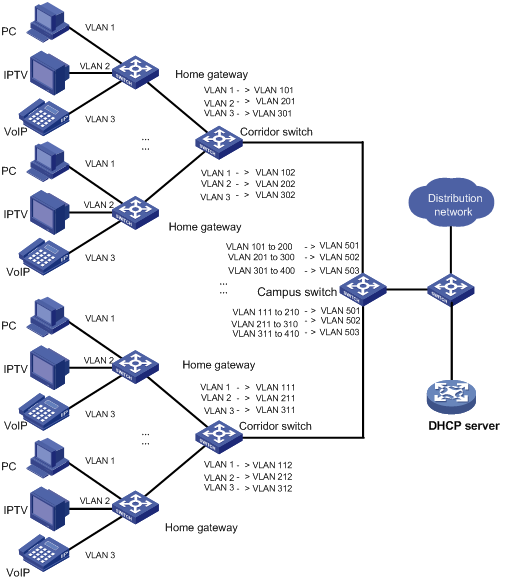
In the scenario presented in Figure 1-3, to save VLAN resources, use one VLAN to carry a type of service traffic from Switch C at the campus network edge while isolating the traffic of a home user from the traffic of all other home users in the VLAN.
Use VLAN 501 for PC traffic, VLAN 502 for IPTV traffic, and VLAN 503 for VoIP traffic.
Network diagram
Figure 1-3 Scenario for one-to-one/multiple-to-one VLAN mapping
Configuration procedure
1) Configuration on Switch A
# Enter system view.
<SwitchA> system-view
# Create the CVLANs and the SVLANs.
[SwitchA] vlan 2 to 3
[SwitchA] vlan 101 to 102
[SwitchA] vlan 201 to 202
[SwitchA] vlan 301 to 302
# Configure uplink policies to map the CVLANs to the SVLANs.
[SwitchA] traffic classifier c1
[SwitchA-classifier-c1] if-match customer-vlan-id 1
[SwitchA-classifier-c1] traffic classifier c2
[SwitchA-classifier-c2] if-match customer-vlan-id 2
[SwitchA-classifier-c2] traffic classifier c3
[SwitchA-classifier-c3] if-match customer-vlan-id 3
[SwitchA-classifier-c3] quit
[SwitchA] traffic behavior b1
[SwitchA-behavior-b1] remark service-vlan-id 101
[SwitchA-behavior-b1] traffic behavior b2
[SwitchA-behavior-b2] remark service-vlan-id 201
[SwitchA-behavior-b2] traffic behavior b3
[SwitchA-behavior-b3] remark service-vlan-id 301
[SwitchA-behavior-b3] traffic behavior b4
[SwitchA-behavior-b4] remark service-vlan-id 102
[SwitchA-behavior-b4] traffic behavior b5
[SwitchA-behavior-b5] remark service-vlan-id 202
[SwitchA-behavior-b5] traffic behavior b6
[SwitchA-behavior-b6] remark service-vlan-id 302
[SwitchA-behavior-b6] quit
[SwitchA] qos policy p1
[SwitchA-policy-p1] classifier c1 behavior b1
[SwitchA-policy-p1] classifier c2 behavior b2
[SwitchA-policy-p1] classifier c3 behavior b3
[SwitchA-policy-p1] quit
[SwitchA] qos policy p2
[SwitchA-policy-p2] classifier c1 behavior b4
[SwitchA-policy-p2] classifier c2 behavior b5
[SwitchA-policy-p2] classifier c3 behavior b6
[SwitchA-policy-p2] quit
# Configure downlink policies to map the SVLANs to the original CVLANs.
[SwitchA] traffic classifier c11
[SwitchA-classifier-c11] if-match service-vlan-id 101
[SwitchA-classifier-c11] traffic classifier c22
[SwitchA-classifier-c22] if-match service-vlan-id 201
[SwitchA-classifier-c22] traffic classifier c33
[SwitchA-classifier-c33] if-match service-vlan-id 301
[SwitchA-classifier-c33] traffic classifier c44
[SwitchA-classifier-c44] if-match service-vlan-id 102
[SwitchA-classifier-c44] traffic classifier c55
[SwitchA-classifier-c55] if-match service-vlan-id 202
[SwitchA-classifier-c55] traffic classifier c66
[SwitchA-classifier-c66] if-match service-vlan-id 302
[SwitchA-classifier-c66] quit
[SwitchA] traffic behavior b11
[SwitchA-behavior-b11] remark customer-vlan-id 1
[SwitchA-behavior-b11] traffic behavior b22
[SwitchA-behavior-b22] remark customer-vlan-id 2
[SwitchA-behavior-b22] traffic behavior b33
[SwitchA-behavior-b33] remark customer-vlan-id 3
[SwitchA-behavior-b33] quit
[SwitchA] qos policy p11
[SwitchA-policy-p11] classifier c11 behavior b11
[SwitchA-policy-p11] classifier c22 behavior b22
[SwitchA-policy-p11] classifier c33 behavior b33
[SwitchA-policy-p11] quit
[SwitchA] qos policy p22
[SwitchA-policy-p22] classifier c44 behavior b11
[SwitchA-policy-p22] classifier c55 behavior b22
[SwitchA-policy-p22] classifier c66 behavior b33
[SwitchA-policy-p22] quit
# Configure GigabitEthernet 2/0/1 to permit frames of the specified CVLANs and SVLANs to pass through.
[SwitchA] interface gigabitethernet 2/0/1
[SwitchA-GigabitEthernet2/0/1] port link-type trunk
[SwitchA-GigabitEthernet2/0/1] port trunk permit vlan 1 2 3 101 201 301
# Enable basic QinQ on GigabitEthernet 2/0/1.
[SwitchA-GigabitEthernet2/0/1] qinq enable
# Apply the uplink policy p1 to the inbound direction of GigabitEthernet 2/0/1.
[SwitchA-GigabitEthernet2/0/1] qos apply policy p1 inbound
# Apply the downlink policy p11 to the outbound direction of GigabitEthernet 2/0/1.
[SwitchA-GigabitEthernet2/0/1] qos apply policy p11 outbound
[SwitchA-GigabitEthernet2/0/1] quit
# Configure GigabitEthernet 2/0/2 to permit frames of the specified CVLANs and SVLANs to pass through.
[SwitchA] interface gigabitethernet 2/0/2
[SwitchA-GigabitEthernet2/0/2] port link-type trunk
[SwitchA-GigabitEthernet2/0/2] port trunk permit vlan 1 2 3 102 202 302
# Enable basic QinQ on GigabitEthernet 2/0/2.
[SwitchA-GigabitEthernet2/0/2] qinq enable
# Apply the uplink policy p2 to the inbound direction of GigabitEthernet 2/0/2.
[SwitchA-GigabitEthernet2/0/2] qos apply policy p2 inbound
# Apply the downlink policy p22 to the outbound direction of GigabitEthernet 2/0/2.
[SwitchA-GigabitEthernet2/0/2] qos apply policy p22 outbound
[SwitchA-GigabitEthernet2/0/2] quit
# Configure GigabitEthernet 2/0/3 to permit frames of the specified SVLANs to pass through.
[SwitchA] interface gigabitethernet 2/0/3
[SwitchA-GigabitEthernet2/0/3] port link-type trunk
[SwitchA-GigabitEthernet2/0/3] port trunk permit vlan 101 201 301 102 202 302
2) Configuration on Switch B
<SwitchB> system-view
# Create the CVLANs and the SVLANs.
[SwitchB] vlan 2 to 3
[SwitchB] vlan 111 to 112
[SwitchB] vlan 211 to 212
[SwitchB] vlan 311 to 312
# Configure uplink policies to map the CVLANs to the SVLANs.
[SwitchB] traffic classifier c1
[SwitchB-classifier-c1] if-match customer-vlan-id 1
[SwitchB-classifier-c1] traffic classifier c2
[SwitchB-classifier-c2] if-match customer-vlan-id 2
[SwitchB-classifier-c2] traffic classifier c3
[SwitchB-classifier-c3] if-match customer-vlan-id 3
[SwitchB-classifier-c3] quit
[SwitchB] traffic behavior b1
[SwitchB-behavior-b1] remark service-vlan-id 111
[SwitchB-behavior-b1] traffic behavior b2
[SwitchB-behavior-b2] remark service-vlan-id 211
[SwitchB-behavior-b2] traffic behavior b3
[SwitchB-behavior-b3] remark service-vlan-id 311
[SwitchB-behavior-b3] traffic behavior b4
[SwitchB-behavior-b4] remark service-vlan-id 112
[SwitchB-behavior-b4] traffic behavior b5
[SwitchB-behavior-b5] remark service-vlan-id 212
[SwitchB-behavior-b5] traffic behavior b6
[SwitchB-behavior-b6] remark service-vlan-id 312
[SwitchB-behavior-b6] quit
[SwitchB] qos policy p1
[SwitchB-policy-p1] classifier c1 behavior b1
[SwitchB-policy-p1] classifier c2 behavior b2
[SwitchB-policy-p1] classifier c3 behavior b3
[SwitchB-policy-p1] quit
[SwitchB] qos policy p2
[SwitchB-policy-p2] classifier c1 behavior b4
[SwitchB-policy-p2] classifier c2 behavior b5
[SwitchB-policy-p2] classifier c3 behavior b6
[SwitchB-policy-p2] quit
# Configure downlink policies to map the SVLANs to the original CVLANs.
[SwitchB] traffic classifier c11
[SwitchB-classifier-c11] if-match service-vlan-id 111
[SwitchB-classifier-c11] traffic classifier c22
[SwitchB-classifier-c22] if-match service-vlan-id 211
[SwitchB-classifier-c22] traffic classifier c33
[SwitchB-classifier-c33] if-match service-vlan-id 311
[SwitchB-classifier-c33] traffic classifier c44
[SwitchB-classifier-c44] if-match service-vlan-id 112
[SwitchB-classifier-c44] traffic classifier c55
[SwitchB-classifier-c55] if-match service-vlan-id 212
[SwitchB-classifier-c55] traffic classifier c66
[SwitchB-classifier-c66] if-match service-vlan-id 312
[SwitchB-classifier-c66] quit
[SwitchB] traffic behavior b11
[SwitchB-behavior-b11] remark customer-vlan-id 1
[SwitchB-behavior-b11] traffic behavior b22
[SwitchB-behavior-b22] remark customer-vlan-id 2
[SwitchB-behavior-b22] traffic behavior b33
[SwitchB-behavior-b33] remark customer-vlan-id 3
[SwitchB-behavior-b33] quit
[SwitchB] qos policy p11
[SwitchB-policy-p11] classifier c11 behavior b11
[SwitchB-policy-p11] classifier c22 behavior b22
[SwitchB-policy-p11] classifier c33 behavior b33
[SwitchB-policy-p11] quit
[SwitchB] qos policy p22
[SwitchB-policy-p22] classifier c44 behavior b11
[SwitchB-policy-p22] classifier c55 behavior b22
[SwitchB-policy-p22] classifier c66 behavior b33
[SwitchB-policy-p22] quit
# Configure GigabitEthernet 2/0/1 to permit frames of the specified CVLANs and SVLANs to pass through.
[SwitchB] interface gigabitethernet 2/0/1
[SwitchB-GigabitEthernet2/0/1] port link-type trunk
[SwitchB-GigabitEthernet2/0/1] port trunk permit vlan 1 2 3 111 211 311
# Enable basic QinQ on GigabitEthernet 2/0/1.
[SwitchB-GigabitEthernet2/0/1] qinq enable
# Apply the uplink policy p1 to the inbound direction of GigabitEthernet 2/0/1.
[SwitchB-GigabitEthernet2/0/1] qos apply policy p1 inbound
# Apply the downlink policy p11 to the outbound direction of GigabitEthernet 2/0/1.
[SwitchB-GigabitEthernet2/0/1] qos apply policy p11 outbound
[SwitchB-GigabitEthernet2/0/1] quit
# Configure GigabitEthernet 2/0/2 to permit frames of the specified CVLANs and SVLANs to pass through.
[SwitchB] interface gigabitethernet 2/0/2
[SwitchB-GigabitEthernet2/0/2] port link-type trunk
[SwitchB-GigabitEthernet2/0/2] port trunk permit vlan 1 2 3 112 212 312
# Enable basic QinQ on GigabitEthernet 2/0/2.
[SwitchB-GigabitEthernet2/0/2] qinq enable
# Apply the uplink policy p2 to the inbound direction of GigabitEthernet 2/0/2.
[SwitchB-GigabitEthernet2/0/2] qos apply policy p2 inbound
# Apply the downlink policy p22 to the outbound direction of GigabitEthernet 2/0/2.
[SwitchB-GigabitEthernet2/0/2] qos apply policy p22 outbound
[SwitchB-GigabitEthernet2/0/2] quit
# Configure GigabitEthernet 2/0/3 to permit frames of the specified SVLANs to pass through.
[SwitchB] interface gigabitethernet 2/0/3
[SwitchB-GigabitEthernet2/0/3] port link-type trunk
[SwitchB-GigabitEthernet2/0/3] port trunk permit vlan 111 211 311 112 212 312
3) Configuration on Switch C
<SwitchC> system-view
# Enable DHCP snooping.
[SwitchC] dhcp-snooping
# Enable ARP detection on each VLAN involved in VLAN mapping.
[SwitchC] vlan 101
[SwitchC-vlan101] arp detection enable
[SwitchC-vlan101] vlan 201
[SwitchC-vlan201] arp detection enable
[SwitchC-vlan201] vlan 301
[SwitchC-vlan301] arp detection enable
[SwitchC-vlan301] vlan 102
[SwitchC-vlan102] arp detection enable
[SwitchC-vlan102] vlan 202
[SwitchC-vlan202] arp detection enable
[SwitchC-vlan202] vlan 302
[SwitchC-vlan302] arp detection enable
[SwitchC-vlan302] vlan 111
[SwitchC-vlan111] arp detection enable
[SwitchC-vlan111] vlan 211
[SwitchC-vlan211] arp detection enable
[SwitchC-vlan211] vlan 311
[SwitchC-vlan311] arp detection enable
[SwitchC-vlan311] vlan 112
[SwitchC-vlan112] arp detection enable
[SwitchC-vlan112] vlan 212
[SwitchC-vlan212] arp detection enable
[SwitchC-vlan212] vlan 312
[SwitchC-vlan312] arp detection enable
[SwitchC-vlan312] vlan 501
[SwitchC-vlan501] arp detection enable
[SwitchC-vlan501] vlan 502
[SwitchC-vlan502] arp detection enable
[SwitchC-vlan502] vlan 503
[SwitchC-vlan503] arp detection enable
[SwitchC-vlan503] quit
# Configure uplink policies to map the CVLANs for the same service of different users to the same SVLAN.
[SwitchC] traffic classifier c1
[SwitchC-classifier-c1] if-match customer-vlan-id 101 to 200
[SwitchC-classifier-c1] traffic classifier c2
[SwitchC-classifier-c2] if-match customer-vlan-id 201 to 300
[SwitchC-classifier-c2] traffic classifier c3
[SwitchC-classifier-c3] if-match customer-vlan-id 301 to 400
[SwitchC-classifier-c3] traffic classifier c4
[SwitchC-classifier-c4] if-match customer-vlan-id 111 to 210
[SwitchC-classifier-c4] traffic classifier c5
[SwitchC-classifier-c5] if-match customer-vlan-id 211 to 310
[SwitchC-classifier-c5] traffic classifier c6
[SwitchC-classifier-c6] if-match customer-vlan-id 311 to 410
[SwitchC-classifier-c6] quit
[SwitchC] traffic behavior b1
[SwitchC-behavior-b1] remark service-vlan-id 501
[SwitchC-behavior-b1] traffic behavior b2
[SwitchC-behavior-b2] remark service-vlan-id 502
[SwitchC-behavior-b2] traffic behavior b3
[SwitchC-behavior-b3] remark service-vlan-id 503
[SwitchC-behavior-b3] quit
[SwitchC] qos policy p1
[SwitchC-policy-p1] classifier c1 behavior b1 mode dot1q-tag-manipulation
[SwitchC-policy-p1] classifier c2 behavior b2 mode dot1q-tag-manipulation
[SwitchC-policy-p1] classifier c3 behavior b3 mode dot1q-tag-manipulation
[SwitchC-policy-p1] classifier c4 behavior b1 mode dot1q-tag-manipulation
[SwitchC-policy-p1] classifier c5 behavior b2 mode dot1q-tag-manipulation
[SwitchC-policy-p1] classifier c6 behavior b3 mode dot1q-tag-manipulation
[SwitchC-policy-p1] quit
# Configure GigabitEthernet 2/0/1 to permit frames of the specified CVLANs and SVLANs to pass through.
[SwitchC] interface gigabitethernet 2/0/1
[SwitchC-GigabitEthernet2/0/1] port link-type trunk
[SwitchC-GigabitEthernet2/0/1] port trunk permit vlan 101 201 301 102 202 302 501 502 503
# Enable customer-side QinQ on GigabitEthernet 2/0/1.
[SwitchC-GigabitEthernet2/0/1] qinq enable downlink
# Apply the uplink policy p1 to the inbound direction of GigabitEthernet 2/0/1.
[SwitchC-GigabitEthernet2/0/1] qos apply policy p1 inbound
[SwitchC-GigabitEthernet2/0/1] quit
# Configure GigabitEthernet 2/0/2 to permit frames of the specified CVLANs and SVLANs to pass through.
[SwitchC] interface gigabitethernet 2/0/2
[SwitchC-GigabitEthernet2/0/2] port link-type trunk
[SwitchC-GigabitEthernet2/0/2] port trunk permit vlan 111 211 311 112 212 312 501 502 503
# Enable customer-side QinQ on GigabitEthernet 2/0/2.
[SwitchC-GigabitEthernet2/0/2] qinq enable downlink
# Apply the uplink policy p2 to the inbound direction of GigabitEthernet 2/0/2.
[SwitchC-GigabitEthernet2/0/2] qos apply policy p2 inbound
[SwitchC-GigabitEthernet2/0/2] quit
# Configure GigabitEthernet 2/0/3 to permit frames of the specified SVLANs to pass through.
[SwitchC] interface gigabitethernet 2/0/3
[SwitchC-GigabitEthernet2/0/3] port link-type trunk
[SwitchC-GigabitEthernet2/0/3] port trunk permit vlan 501 502 503
# Configure GigabitEthernet 2/0/3 as a DHCP snooping trusted port.
[SwitchC-GigabitEthernet2/0/3] dhcp-snooping trust
# Configure GigabitEthernet 2/0/3 as an ARP trusted port.
[SwitchC-GigabitEthernet2/0/3] arp detection trust
# Enable SP-side QinQ on GigabitEthernet 2/0/3.
[SwitchC-GigabitEthernet2/0/3] qinq enable uplink
4) Configuration on Switch D
<SwitchD> system-view
# Enable DHCP snooping.
[SwitchD] dhcp-snooping
# Configure GigabitEthernet 2/0/1 to permit frames of the specified SVLANs to pass through.
[SwitchD] interface gigabitethernet 2/0/1
[SwitchD-GigabitEthernet2/0/1] port link-type trunk
[SwitchD-GigabitEthernet2/0/1] port trunk permit vlan 501 502 503
# Configure GigabitEthernet 2/0/1 as a DHCP snooping trusted port and disable DHCP snooping to record the IP-to-MAC bindings for DHCP clients on it.
[SwitchD-GigabitEthernet2/0/1] dhcp-snooping trust no-user-binding
One-to-Two/Two-to-Two VLAN Mapping Configuration Example
Network requirements
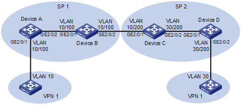
l Two users of the same VPN are in VLAN 10 and VLAN 30 respectively.
l SP 1 assigns VLAN 100 to VPN 1 users, and SP 2 assigns VLAN 200 to VPN 1 users.
Configure one-to-two and two-to-two VLAN mappings to allow the users that belong to the same VPN but are located in different regions to communicate with each other across the networks of SP 1 and SP 2.
Network diagram
Figure 1-4 Network diagram for one-to-two/two-to-two VLAN mapping configuration
Configuration procedure
1) Configuration on Device A
# Configure an uplink policy nest to add outer VLAN tag 100 to the traffic tagged with VLAN 10.
<DeviceA> system-view
[DeviceA] traffic classifier nest
[DeviceA-classifier-nest] if-match customer-vlan-id 10
[DeviceA-classifier-nest] quit
[DeviceA] traffic behavior nest
[DeviceA-behavior-nest] nest top-most vlan-id 100
[DeviceA-behavior-nest] quit
[DeviceA] qos policy nest
[DeviceA-qospolicy-nest] classifier nest behavior nest
[DeviceA-qospolicy-nest] quit
# Configure GigabitEthernet 2/0/1 to forward the traffic of VLAN 100 with the outer VLAN tag removed.
[DeviceA] interface gigabitethernet 2/0/1
[DeviceA-GigabitEthernet2/0/1] port link-type hybrid
[DeviceA-GigabitEthernet2/0/1] port hybrid vlan 100 untagged
# Enable basic QinQ on GigabitEthernet 2/0/1.
[DeviceA-GigabitEthernet2/0/1] qinq enable
# Apply the uplink policy nest to the inbound direction of GigabitEthernet 2/0/1.
[DeviceA-GigabitEthernet2/0/1] qos apply policy nest inbound
[DeviceA-GigabitEthernet2/0/1] quit
# Configure the uplink port GigabitEthernet 2/0/2 to permit frames of VLAN 100 to pass through.
[DeviceA] interface gigabitethernet 2/0/2
[DeviceA-GigabitEthernet2/0/2] port link-type trunk
[DeviceA-GigabitEthernet2/0/2] port trunk permit vlan 100
2) Configuration on Device B
# Enter system view.
<DeviceB> system-view
# Configure GigabitEthernet 2/0/1 to permit frames of VLAN 100 to pass through.
[DeviceB] interface gigabitethernet 2/0/1
[DeviceB-GigabitEthernet2/0/1] port link-type trunk
[DeviceB-GigabitEthernet2/0/1] port trunk permit vlan 100
[DeviceB-GigabitEthernet2/0/1] quit
# Configure GigabitEthernet 2/0/2 to permit frames of VLAN 100 to pass through.
[DeviceB] interface gigabitethernet 2/0/2
[DeviceB-GigabitEthernet2/0/2] port link-type trunk
[DeviceB-GigabitEthernet2/0/2] port trunk permit vlan 100
3) Configuration on Device C
# Specify the original CVLAN and SVLAN in the VLAN mapping for VPN 1 traffic received on GigabitEthernet 2/0/1.
<DeviceC> system-view
[DeviceC] traffic classifier downlink_in
[DeviceC-classifier-downlink_in] if-match customer-vlan-id 10
[DeviceC-classifier-downlink_in] if-match service-vlan-id 100
[DeviceC-classifier-downlink_in] quit
# Specify the new SVLAN used for replacing the original SVLAN for incoming VPN 1 traffic on GigabitEthernet 2/0/1.
[DeviceC] traffic behavior downlink_in
[DeviceC-behavior-downlink_in] remark service-vlan-id 200
[DeviceC-behavior-downlink_in] quit
# Configure an uplink policy to map the original SVLAN and CVLAN to the new SVLAN.
[DeviceC] qos policy downlink_in
[DeviceC-qospolicy-downlink_in] classifier downlink_in behavior downlink_in
[DeviceC-qospolicy-downlink_in] quit
# Specify the new CVLAN and SVLAN in the VLAN mapping for outgoing VPN 1 traffic on GigabitEthernet 2/0/1.
[DeviceC] traffic classifier downlink_out
[DeviceC-classifier-downlink_out] if-match customer-vlan-id 30
[DeviceC-classifier-downlink_out] if-match service-vlan-id 200
[DeviceC-classifier-downlink_out] quit
# Specify the original CVLAN and SVLAN for outgoing VPN 1 traffic on GigabitEthernet 2/0/1.
[DeviceC] traffic behavior downlink_out
[DeviceC-behavior-downlink_out] remark customer-vlan-id 10
[DeviceC-behavior-downlink_out] remark service-vlan-id 100
[DeviceC-behavior-downlink_out] quit
# Configure a downlink policy to map the new CVLAN and SVLAN to the original CVLAN and SVLAN for the outgoing VPN 1 traffic on GigabitEthernet 2/0/1.
[DeviceC] qos policy downlink_out
[DeviceC-qospolicy-downlink_out] classifier downlink_out behavior downlink_out
[DeviceC-qospolicy-downlink_out] quit
# Specify the original CVLAN and the new SVLAN in the VLAN mapping for outgoing VPN 1 traffic on GigabitEthernet 2/0/2.
[DeviceC] traffic classifier uplink_out
[DeviceC-classifier-uplink_out] if-match customer-vlan-id 10
[DeviceC-classifier-uplink_out] if-match service-vlan-id 200
[DeviceC-classifier-uplink_out] quit
# Specify the new CVLAN used for replacing the original CVLAN for outgoing VPN 1 traffic on GigabitEthernet 2/0/2.
[DeviceC] traffic behavior uplink_out
[DeviceC-behavior-uplink_out] remark customer-vlan-id 30
[DeviceC-behavior-uplink_out] quit
# Configure an uplink policy to map the original CVLAN and the new SVLAN to the new CVLAN for outgoing VPN 1 traffic on GigabitEthernet 2/0/2.
[DeviceC] qos policy uplink_out
[DeviceC-qospolicy-uplink_out] classifier uplink_out behavior uplink_out
[DeviceC-qospolicy-uplink_out] quit
# Apply uplink and downlink policies to GigabitEthernet 2/0/1 and GigabitEthernet 2/0/2.
[DeviceC] interface gigabitethernet 2/0/1
[DeviceB-GigabitEthernet2/0/1] port link-type trunk
[DeviceB-GigabitEthernet2/0/1] port trunk permit vlan 200
[DeviceC-GigabitEthernet2/0/1] qos apply policy downlink_in inbound
[DeviceC-GigabitEthernet2/0/1] qos apply policy downlink_out outbound
[DeviceC-GigabitEthernet2/0/1] quit
[DeviceC] interface gigabitethernet 2/0/2
[DeviceB-GigabitEthernet2/0/2] port link-type trunk
[DeviceB-GigabitEthernet2/0/2] port trunk permit vlan 200
[DeviceC-GigabitEthernet2/0/2] qos apply policy uplink_out outbound
[DeviceC-GigabitEthernet2/0/2] quit
4) Configuration on Device D
# Configure an uplink policy nest to add outer VLAN tag 200 to the traffic tagged with VLAN 30.
<DeviceD> system-view
[DeviceD] traffic classifier nest
[DeviceD-classifier-nest] if-match customer-vlan-id 30
[DeviceD-classifier-nest] quit
[DeviceD] traffic behavior nest
[DeviceD-behavior-nest] nest top-most vlan-id 200
[DeviceD-behavior-nest] quit
[DeviceD] qos policy nest
[DeviceD-qospolicy-nest] classifier nest behavior nest
[DeviceD-qospolicy-nest] quit
# Configure GigabitEthernet 2/0/1 to permit frames of VLAN 200 to pass through.
[DeviceD] interface gigabitethernet 2/0/1
[DeviceD-GigabitEthernet2/0/1] port link-type trunk
[DeviceD-GigabitEthernet2/0/1] port trunk permit vlan 200
# Configure GigabitEthernet 2/0/2 to forward the traffic of VLAN 200 with the outer VLAN tag removed.
[DeviceD] interface gigabitethernet 2/0/2
[DeviceD-GigabitEthernet2/0/2] port link-type hybrid
[DeviceD-GigabitEthernet2/0/2] port hybrid vlan 200 untagged
# Enable basic QinQ on GigabitEthernet 2/0/2.
[DeviceD-GigabitEthernet2/0/2] qinq enable
# Apply the uplink policy nest to the inbound direction of GigabitEthernet 2/0/2.
[DeviceD-GigabitEthernet2/0/2] qos apply policy nest inbound
[DeviceD-GigabitEthernet2/0/2] quit
