- Table of Contents
-
- 01-Access Volume
- 00-Access Volume Organization
- 01-Ethernet Interface Configuration
- 02-Link Aggregation Configuration
- 03-Port Isolation Configuration
- 04-Service Loopback Group Configuration
- 05-DLDP Configuration
- 06-Smart Link Configuration
- 07-LLDP Configuration
- 08-VLAN Configuration
- 09-GVRP Configuration
- 10-QinQ Configuration
- 11-BPDU Tunneling Configuration
- 12-VLAN Mapping Configuration
- 13-Ethernet OAM Configuration
- 14-Connectivity Fault Detection Configuration
- 15-EPON-OLT Configuration
- 16-MSTP Configuration
- 17-RRPP Configuration
- 18-Mirroring Configuration
- Related Documents
-
| Title | Size | Download |
|---|---|---|
| 06-Smart Link Configuration | 145.45 KB |
Table of Contents
Operating Mechanism of Smart Link
Configuring a Smart Link Device
Configuring a Smart Link Device
Smart Link Device Configuration Example
Configuring an Associated Device
Configuring an Associated Device
Associated Device Configuration Example
Displaying and Maintaining Smart Link
Smart Link Configuration Examples
Single Smart Link Group Configuration Example
Multiple Smart Link Groups Load Sharing Configuration Example
When configuring Smart Link, go to these sections for information that you are interested in:
l Configuring a Smart Link Device
l Configuring an Associated Device
l Displaying and Maintaining Smart Link
l Smart Link Configuration Examples
Smart Link Overview
Smart Link is a feature developed to address the slow convergence issue with the Spanning Tree Protocol (STP). (For information about STP, refer to MSTP Configuration in the Access Volume.)
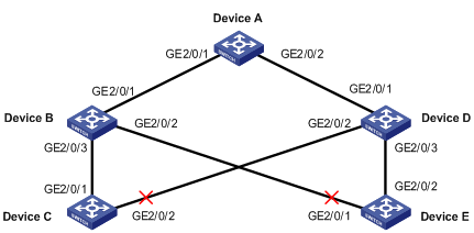
Smart Link is dedicated to dual-uplink networks as shown in Figure 1-1 to provide link redundancy with subsecond convergence. It allows the backup link to take over quickly when the primary link fails. In addition to fast convergence, Smart Link is easy to configure.
Terminology
Figure 1-1 Smart Link application scenario
Smart link group
A smart link group consists of only two member ports: the master and the slave. At a time, only one port is active for forwarding, and the other port is blocked, that is, in the standby state. When link failure occurs on the active port due to port shutdown or presence of unidirectional link for example, the standby port becomes active to take over while the original active port transits to the blocked state.
As shown in Figure 1-1, GigabitEthernet 2/0/1 and GigabitEthernet 2/0/2 of Device C form a smart link group, with GigabitEthernet 2/0/1 being active and GigabitEthernet 2/0/2 being standby. GigabitEthernet 2/0/1 and GigabitEthernet 2/0/2 of Device E form another smart link group, with GigabitEthernet 2/0/2 being active and GigabitEthernet 2/0/1 being standby.
Master port
Master port is a port role in a smart link group. When both ports in a smart link group are up, the master port preferentially transits to the forwarding state. Once the master port fails, the slave port takes over to forward traffic. During this period, if the smart link group is not configured with role preemption, the master port stays in standby state until the next link switchover even if it has recovered.
As shown in Figure 1-1, you can configure GigabitEthernet 2/0/1 of Device C and GigabitEthernet 2/0/2 of Device E as master ports.
Slave port
As shown in Figure 1-1, you can configure GigabitEthernet 2/0/2 of Device C and GigabitEthernet 2/0/1 of Device E as slave ports.
Flush message
Flush messages are used by a smart link group to notify other devices to refresh their MAC address forwarding entries and ARP/ND entries when link switchover occurs in the smart link group. Flush messages are common multicast data packets, and will be dropped by a blocked receiving port.
Transmit control VLAN
The transmit control VLAN is used for transmitting flush messages. When link switchover occurs, the devices (such as Device C and E in Figure 1-1) broadcast flush messages within the transmit control VLAN.
Receive control VLAN
The receive control VLAN is used for receiving and processing flush messages. When link switchover occurs, the devices (such as Device A, B, and D in Figure 1-1) receive and process flush messages in the receive control VLAN and refresh their MAC address forwarding entries and ARP/ND entries.
Protected VLAN
A smart link group controls the forwarding state of some data VLANs, which are referred to as protected VLANs. Different smart link groups on a port control different protected VLANs. The state of the port in a protected VLAN is determined by the state of the port in the smart link group.
Operating Mechanism of Smart Link
Link backup mechanism
As shown in Figure 1-1, the link on GigabitEthernet 2/0/1 of Device C is the active link, and the link on GigabitEthernet 2/0/2 of Device C is the standby link. Normally, GigabitEthernet 2/0/1 is in the forwarding state, while GigabitEthernet 2/0/2 is in the standby state. When the link on GigabitEthernet 2/0/1 fails, GigabitEthernet 2/0/2 takes over to forward traffic while GigabitEthernet 2/0/1 is blocked and placed in the standby state.
When a port switches to the forwarding state, the system outputs log information to notify the user of the port state change.
As link switchover can outdate the MAC address forwarding entries and ARP/ND entries on all devices, you need a forwarding entry update mechanism to ensure proper transmission. By far, the following two update mechanisms are provided:
l Uplink traffic-triggered MAC address learning, where update is triggered by uplink traffic. This mechanism is applicable to environments with devices not supporting smart link, including devices of other vendors’.
l Flush update where a Smart Link-enabled device updates its information by transmitting flush messages over the backup link to its upstream devices. This mechanism requires the upstream devices to be capable of recognizing smart link flush messages to update its MAC address forwarding entries and ARP/ND entries.
To keep traffic forwarding stable, the master port that has been blocked due to link failure does not take over immediately upon its recovery. Instead, link switchover will occur at next link switchover.
Role preemption mechanism
As shown in Figure 1-1, the link on GigabitEthernet 2/0/1 of Device C is the active link, and the link on GigabitEthernet 2/0/2 of Device C is the standby link. Once GigabitEthernet 2/0/1 fails, GigabitEthernet 2/0/2 takes over to forward traffic. During this period, if the smart link group is configured with role preemption, GigabitEthernet 2/0/1 takes over to forward traffic as soon as it recovers.
Load sharing mechanism
A ring network may carry traffic of multiple VLANs. Smart link can forward traffic of different VLANs in different smart link groups, thus implementing load sharing.
To implement load sharing, you can assign a port to multiple smart link groups (each configured with different protected VLANs), making sure that the state of the port is different in these smart link groups. In this way, traffic of different VLANs can be forwarded along different paths.
You can configure protected VLANs for a smart link group by referencing MSTIs.
Configuring a Smart Link Device
To use Smart Link on a device, you must configure the device with a smart link group and transmit control VLAN for flush message transmission. Device C and Device E in Figure 1-1 are two examples of Smart Link devices.
Configuration Prerequisites
l Before configuring a port as a smart link group member, shut down the port to prevent loops. You can bring up the port only after completing the smart link group configuration.
l Disable STP and RRPP on the ports you want to add to the smart link group, and make sure that the ports are not member ports of any aggregation group or service loopback group.
Configuring a Smart Link Device
Follow these steps to configure a smart link device:
|
To do… |
Use the command… |
Remarks |
|
|
Enter system view |
system-view |
— |
|
|
Create a smart link group and enter smart link group view |
smart-link group group-id |
Required |
|
|
Configure protected VLANs for the smart link group |
protected-vlan reference-instance instance-id-list |
Required By default, no protected VLAN is configured for a smart link group. |
|
|
Specify the master port for the smart link group |
In smart link group view |
port interface-type interface-number master |
Required Use either approach. |
|
In Ethernet interface view or Layer-2 aggregate interface view |
port smart-link group group-id master |
||
|
Specify the slave port for the smart link group |
In smart link group view |
port interface-type interface-number slave |
Required Use either approach. |
|
In Ethernet interface view or Layer-2 aggregate interface view |
port smart-link group group-id slave |
||
|
Enable role preemption |
preemption mode role |
Optional Disabled by default. |
|
|
Enable flush update in the specified control VLAN |
flush enable [ control-vlan vlan-id ] |
Optional By default, VLAN 1 is used for flush update. |
|
![]()
l The protected-vlan command configures protected VLANs for a smart link group by referencing MSTIs. To view VLAN-to-MSTI mappings, use the display stp region-configuration command. For VLAN-to-MSTI mapping configuration, refer to MSTP Configuration in the Access Volume.
l The protected VLANs configured for a smart link group must be different from those configured for any other smart link group.
l Make sure that the configured control VLANs are existing VLANs, and you must assign the smart link group member ports to the control VLANs.
l Do not remove the control VLANs. Otherwise, flush messages cannot be sent properly.
Smart Link Device Configuration Example
Network requirements
l Create smart link group 1.
l The protected VLANs of smart link group 1 are mapped to MSTI 0 through 8.
l Configure GigabitEthernet 2/0/1 as the master port of the smart link group, and GigabitEthernet 2/0/2 as the slave port.
l Configure VLAN 20 for flush update.
Configuration procedure
<Sysname> system-view
[Sysname] vlan 20
[Sysname-vlan20] quit
[Sysname] interface GigabitEthernet 2/0/1
[Sysname-GigabitEthernet2/0/1] stp disable
[Sysname-GigabitEthernet2/0/1] port link-type trunk
[Sysname-GigabitEthernet2/0/1] port trunk permit vlan 20
[Sysname-GigabitEthernet2/0/1] quit
[Sysname] interface GigabitEthernet 2/0/2
[Sysname-GigabitEthernet2/0/2] stp disable
[Sysname-GigabitEthernet2/0/2] port link-type trunk
[Sysname-GigabitEthernet2/0/2] port trunk permit vlan 20
[Sysname-GigabitEthernet2/0/2] quit
[Sysname] smart-link group 1
[Sysname-smlk-group1] protected-vlan reference-instance 0 to 8
[Sysname-smlk-group1] port GigabitEthernet2/0/1 master
[Sysname-smlk-group1] port GigabitEthernet2/0/2 slave
[Sysname-smlk-group1] flush enable control-vlan 20
Configuring an Associated Device
The active and standby links in a smart link group may traverse multiple devices between the Smart Link device and the destination device. For Smart Link to work, you need to enable all the ports on the way to the destination to process the flush messages sent from the smart link device.
For example, as all the numbered ports on Device A, B, and D in Figure 1-1 are on the way of the active and standby links from Device C and E to Device A, you need to enable the ports to process flush messages received from the control VLAN configured on Device C and E.
Configuring an Associated Device
Follow these steps to configure an associated device:
|
To do… |
Use the command… |
Remarks |
|
Enter system view |
system-view |
— |
|
Enter Ethernet interface view or Layer-2 aggregate interface view |
interface interface-type interface-number |
— |
|
Configure the control VLAN for receiving flush messages |
smart-link flush enable [ control-vlan vlan-id-list ] |
Required No control VLAN exists for receiving flush messages of Smart Link by default. |
![]()
l Configure all the control VLANs to receive flush messages.
l If no control VLAN is specified for processing flush messages, the device forwards the received flush messages directly without processing them.
l Make sure that the receive control VLAN is the same as the transmit control VLAN configured on the Smart Link device. If they are not the same, the associated device will forward the received flush messages directly without any processing.
l Do not remove the control VLANs. Otherwise, flush messages cannot be sent properly.
l Make sure that the control VLANs are existing VLANs, and you must assign the port capable of receiving flush messages to the control VLANs.
Associated Device Configuration Example
Network requirements
Configure GigabitEthernet 2/0/1 to receive and process flush messages in VLAN 20.
Configuration procedure
<Sysname> system-view
[Sysname] vlan 20
[Sysname-vlan20] quit
[Sysname] interface GigabitEthernet2/0/1
[Sysname-GigabitEthernet2/0/1] port link-type trunk
[Sysname-GigabitEthernet2/0/1] port trunk permit vlan 20
[Sysname-GigabitEthernet2/0/1] smart-link flush enable control-vlan 20
Displaying and Maintaining Smart Link
|
To do... |
Use the command… |
Remarks |
|
Display smart link group information |
display smart-link group { group-id | all } |
Available in any view |
|
Display information about the received flush messages |
display smart-link flush |
Available in any view |
|
Clear the statistics about flush messages |
reset smart-link statistics |
Available in user view |
Smart Link Configuration Examples
Single Smart Link Group Configuration Example
Network requirements
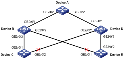
Both Device C and Device E are dually uplinked to Device A.
Configure Smart Link on the devices for uplink backup, adopting VLAN 1 (the default) for flush update.
Network diagram
Figure 1-2 Network diagram for smart link configuration
Configuration procedure
1) Configuration on Device C
# Disable STP on GigabitEthernet 2/0/1 and GigabitEthernet 2/0/2 separately.
<DeviceC> system-view
[DeviceC] interface GigabitEthernet 2/0/1
[DeviceC-GigabitEthernet2/0/1] stp disable
[DeviceC-GigabitEthernet2/0/1] quit
[DeviceC] interface GigabitEthernet 2/0/2
[DeviceC-GigabitEthernet2/0/2] stp disable
[DeviceC-GigabitEthernet2/0/2] quit
# Create smart link group 1 and configure all VLANs mapped to MSTIs 0 through 31 as the protected VLANs.
[DeviceC] smart-link group 1
[DeviceC-smlk-group1] protected-vlan reference-instance 0 to 31
# Configure GigabitEthernet 2/0/1 as the master port and GigabitEthernet 2/0/2 as the slave port.
[DeviceC-smlk-group1] port GigabitEthernet2/0/1 master
[DeviceC-smlk-group1] port GigabitEthernet2/0/2 slave
# Enable flush message sending in smart link group 1.
[DeviceC-smlk-group1] flush enable
[DeviceC-smlk-group1] quit
2) Configuration on Device E
# Disable STP on GigabitEthernet 2/0/1 and GigabitEthernet 2/0/2 separately.
<DeviceE> system-view
[DeviceE] interface GigabitEthernet 2/0/1
[DeviceE-GigabitEthernet2/0/1] stp disable
[DeviceE-GigabitEthernet2/0/1] quit
[DeviceE] interface GigabitEthernet 2/0/2
[DeviceE-GigabitEthernet2/0/2] stp disable
[DeviceE-GigabitEthernet2/0/2] quit
# Create smart link group 1 and configure all VLANs mapped to MSTIs 0 through 31 as the protected VLANs.
[DeviceE] smart-link group 1
[DeviceC-smlk-group1] protected-vlan reference-instance 0 to 31
# Configure GigabitEthernet 2/0/2 as the master port and GigabitEthernet 2/0/1 as the slave port.
[DeviceE-smlk-group1] port GigabitEthernet2/0/2 master
[DeviceE-smlk-group1] port GigabitEthernet2/0/1 slave
# Enable flush message sending in smart link group 1.
[DeviceE-smlk-group1] flush enable
[DeviceE-smlk-group1] quit
3) Configuration on Device B
# Configure VLAN 1 as the receive control VLAN for GigabitEthernet 2/0/1, GigabitEthernet 2/0/2, and GigabitEthernet 2/0/3.
<DeviceB> system-view
[DeviceB] interface GigabitEthernet 2/0/1
[DeviceB-GigabitEthernet2/0/1] smart-link flush enable
[DeviceB-GigabitEthernet2/0/1] quit
[DeviceB] interface GigabitEthernet 2/0/2
[DeviceB-GigabitEthernet2/0/2] smart-link flush enable
[DeviceB-GigabitEthernet2/0/2] quit
[DeviceB] interface GigabitEthernet 2/0/3
[DeviceB-GigabitEthernet2/0/3] smart-link flush enable
[DeviceB-GigabitEthernet2/0/3] quit
4) Configuration on Device D
# Configure VLAN 1 as the receive control VLAN for GigabitEthernet 2/0/1, GigabitEthernet 2/0/2, and GigabitEthernet 2/0/3.
<DeviceD> system-view
[DeviceD] interface GigabitEthernet 2/0/1
[DeviceD-GigabitEthernet2/0/1] smart-link flush enable
[DeviceD-GigabitEthernet2/0/1] quit
[DeviceD] interface GigabitEthernet 2/0/2
[DeviceD-GigabitEthernet2/0/2] smart-link flush enable
[DeviceD-GigabitEthernet2/0/2] quit
[DeviceD] interface GigabitEthernet 2/0/3
[DeviceD-GigabitEthernet2/0/3] smart-link flush enable
[DeviceD-GigabitEthernet2/0/3] quit
5) Configuration on Device A
# Configure VLAN 1 as the receive control VLAN for GigabitEthernet 2/0/1 and GigabitEthernet 2/0/2.
<DeviceA> system-view
[DeviceA] interface GigabitEthernet 2/0/1
[DeviceA-GigabitEthernet2/0/1] smart-link flush enable
[DeviceA-GigabitEthernet2/0/1] quit
[DeviceA] interface GigabitEthernet 2/0/2
[DeviceA-GigabitEthernet2/0/2] smart-link flush enable
[DeviceA-GigabitEthernet2/0/2] quit
6) Verifying the configurations
You can use the display smart-link group command to display the smart link group configuration on each device. For example:
# Display the smart link group configuration on Device C.
[DeviceC] display smart-link group 1
Smart link group 1 information:
Device ID: 000f-e23d-5af0
Preemption mode: NONE
Control VLAN: 1
Protected VLAN: Reference Instance 0 to 31
Member Role State Flush-count Last-flush-time
-------------------------------------------------------------------------------
GigabitEthernet2/0/1 MASTER ACTVIE 5 16:37:20 2009/02/21
GigabitEthernet2/0/2 SLAVE STANDBY 1 17:45:20 2009/02/21
You can use the display smart-link flush command to display the flush messages received on each device. For example:
# Display the flush messages received on Device B.
[DeviceB] display smart-link flush
Received flush packets : 5
Receiving interface of the last flush packet : GigabitEthernet2/0/3
Receiving time of the last flush packet : 16:25:21 2009/02/21
Device ID of the last flush packet : 000f-e23d-5af0
Control VLAN of the last flush packet : 1
Multiple Smart Link Groups Load Sharing Configuration Example
Network requirements
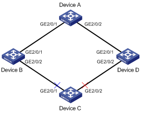
l The traffic of VLAN 1 through VLAN 200 on Device C are dually uplinked to Device A by Device B and Device D. Implement load sharing to uplink the traffic of VLAN 1 through VLAN 100 and the traffic of VLAN 101 through VLAN 200 over different links to Device A.
l Implement dual link backup on Device C: the traffic of VLANs 1 through 100 (mapped to MSTI 0) is uplinked to Device A by Device B; the traffic of VLANs 101 through 200 (mapped to MSTI 2) is uplinked to Device A by Device D. Smart link group 1 references MSTI 0, and smart link group 2 references MSTI 2.
l The control VLAN of smart link group 1 is VLAN 10 and that of smart link group 2 is VLAN 101.
Network diagram
Figure 1-3 Network diagram for multi-instance load sharing configuration
Configuration procedure
1) Configuration on Device C
# Create VLAN 1 through VLAN 200, map VLAN 1 through VLAN 100 to MSTI 0 and VLAN 101 through VLAN 200 to MSTI 2, and activate MST region configuration.
<DeviceC> system-view
[DeviceC] vlan 1 to 200
[DeviceC] stp region-configuration
[DeviceC-mst-region] instance 0 vlan 1 to 100
[DeviceC-mst-region] instance 2 vlan 101 to 200
[DeviceC-mst-region] active region-configuration
[DeviceC-mst-region] quit
# Disable STP on GigabitEthernet 2/0/1 and GigabitEthernet 2/0/2 separately, configure the ports as trunk ports, and assign them to VLAN 1 through VLAN 200.
[DeviceC] interface GigabitEthernet 2/0/1
[DeviceC-GigabitEthernet2/0/1] stp disable
[DeviceC-GigabitEthernet2/0/1] port link-type trunk
[DeviceC-GigabitEthernet2/0/1] port trunk permit vlan 1 to 200
[DeviceC-GigabitEthernet2/0/1] quit
[DeviceC] interface GigabitEthernet 2/0/2
[DeviceC-GigabitEthernet2/0/2] stp disable
[DeviceC-GigabitEthernet2/0/2] port link-type trunk
[DeviceC-GigabitEthernet2/0/2] port trunk permit vlan 1 to 200
[DeviceC-GigabitEthernet2/0/2] quit
# Create smart link group 1.
[DeviceC] smart-link group 1
# Configure protected VLANs for smart link group 1.
[DeviceC-smlk-group1] protected-vlan reference-instance 0
# Configure GigabitEthernet 2/0/1 as the master port and GigabitEthernet 2/0/2 as the slave port.
[DeviceC-smlk-group1] port GigabitEthernet2/0/1 master
[DeviceC-smlk-group1] port GigabitEthernet2/0/2 slave
# Enable role preemption.
[DeviceC-smlk-group1] preemption mode role
# Configure VLAN 10 as the transmit control VLAN of smart link group 1.
[DeviceC-smlk-group-1] flush enable control-vlan 10
[DeviceC-smlk-group-1] quit
# Create smart link group 2.
[DeviceC] smart-link group 2
# Configure protected VLANs for smart link group 2.
[DeviceC-smlk-group2] protected-vlan reference-instance 2
# Configure GigabitEthernet 2/0/1 as the slave port and GigabitEthernet 2/0/2 as the master port.
[DeviceC-smlk-group2] port GigabitEthernet2/0/1 slave
[DeviceC-smlk-group2] port GigabitEthernet2/0/2 master
# Enable role preemption.
[DeviceC-smlk-group2] preemption mode role
# Configure VLAN 101 as the transmit control VLAN of smart link group 2.
[DeviceC-smlk-group2] flush enable control-vlan 101
[DeviceC-smlk-group2] quit
2) Configuration on Device B
# Create VLAN 1 through VLAN 200.
<DeviceB> system-view
[DeviceB] vlan 1 to 200
# Configure GigabitEthernet 2/0/1 and GigabitEthernet 2/0/2 as trunk ports, and assign them to VLAN 1 through 200; enable flush message receiving on GigabitEthernet 2/0/1 and GigabitEthernet 2/0/2 and configure VLAN 10 and VLAN 101 as the receive control VLANs.
[DeviceB] interface GigabitEthernet 2/0/1
[DeviceB-GigabitEthernet2/0/1] port link-type trunk
[DeviceB-GigabitEthernet2/0/1] port trunk permit vlan 1 to 200
[DeviceB-GigabitEthernet2/0/1] smart-link flush enable control-vlan 10 101
[DeviceB-GigabitEthernet2/0/1] quit
[DeviceB] interface GigabitEthernet 2/0/2
[DeviceB-GigabitEthernet2/0/2] port link-type trunk
[DeviceB-GigabitEthernet2/0/2] port trunk permit vlan 1 to 200
[DeviceB-GigabitEthernet2/0/2] smart-link flush enable control-vlan 10 101
[DeviceB-GigabitEthernet2/0/2] quit
3) Configuration on Device D
# Create VLAN 1 through VLAN 200.
<DeviceD> system-view
[DeviceD] vlan 1 to 200
# Configure GigabitEthernet 2/0/1 and GigabitEthernet 2/0/2 as trunk ports, and assign them to VLAN 1 through 200; enable flush message receiving on GigabitEthernet 2/0/1 and GigabitEthernet 2/0/2 and configure VLAN 10 and VLAN 101 as the receive control VLANs.
[DeviceD] interface GigabitEthernet 2/0/1
[DeviceD-GigabitEthernet2/0/1] port link-type trunk
[DeviceD-GigabitEthernet2/0/1] port trunk permit vlan 1 to 200
[DeviceD-GigabitEthernet2/0/1] smart-link flush enable control-vlan 10 101
[DeviceD-GigabitEthernet2/0/1] quit
[DeviceD] interface GigabitEthernet 2/0/2
[DeviceD-GigabitEthernet2/0/2] port link-type trunk
[DeviceD-GigabitEthernet2/0/2] port trunk permit vlan 1 to 200
[DeviceD-GigabitEthernet2/0/2] smart-link flush enable control-vlan 10 101
[DeviceD-GigabitEthernet2/0/2] quit
4) Configuration on Device A
# Create VLAN 1 through VLAN 200.
<DeviceA> system-view
[DeviceA] vlan 1 to 200
# Configure GigabitEthernet 2/0/1 and GigabitEthernet 2/0/2 as trunk ports, and assign them to VLAN 1 through 200; enable flush message receiving on GigabitEthernet 2/0/1 and GigabitEthernet 2/0/2 and configure VLAN 10 and VLAN 101 as the receive control VLANs.
[DeviceA] interface GigabitEthernet 2/0/1
[DeviceA-GigabitEthernet2/0/1] port link-type trunk
[DeviceA-GigabitEthernet2/0/1] port trunk permit vlan 1 to 200
[DeviceA-GigabitEthernet2/0/1] smart-link flush enable control-vlan 10 101
[DeviceA-GigabitEthernet2/0/1] quit
[DeviceA] interface GigabitEthernet 2/0/2
[DeviceA-GigabitEthernet2/0/2] port link-type trunk
[DeviceA-GigabitEthernet2/0/2] port trunk permit vlan 1 to 200
[DeviceA-GigabitEthernet2/0/2] smart-link flush enable control-vlan 10 101
[DeviceA-GigabitEthernet2/0/2] quit
5) Verifying the configurations
You can use the display smart-link group command to display the smart link group configuration on each device. For example:
# Display the smart link group configuration on Device C.
[DeviceC] display smart-link group all
Smart link group 1 information:
Device ID: 000f-e23d-5af0
Preemption mode: ROLE
Control VLAN: 10
Protected VLAN: Reference Instance 0
Member Role State Flush-count Last-flush-time
-------------------------------------------------------------------------------
GigabitEthernet2/0/1 MASTER ACTVIE 5 16:37:20 2009/02/21
GigabitEthernet2/0/2 SLAVE STANDBY 1 17:45:20 2009/02/21
Smart link group 2 information:
Device ID: 000f-e23d-5af0
Preemption mode: ROLE
Control VLAN: 101
Protected VLAN: Reference Instance 2
Member Role State Flush-count Last-flush-time
-------------------------------------------------------------------------------
GigabitEthernet2/0/2 MASTER ACTVIE 5 16:37:20 2009/02/21
GigabitEthernet2/0/1 SLAVE STANDBY 1 17:45:20 2009/02/21
You can use the display smart-link flush command to display the flush messages received on each device. For example:
# Display the flush messages received on Device B.
[DeviceB] display smart-link flush
Received flush packets : 5
Receiving interface of the last flush packet : GigabitEthernet2/0/2
Receiving time of the last flush packet : 16:25:21 2009/02/21
Device ID of the last flush packet : 000f-e23d-5af0
Control VLAN of the last flush packet : 10
