- Table of Contents
-
- 01-Access Volume
- 00-Access Volume Organization
- 01-Ethernet Interface Configuration
- 02-Link Aggregation Configuration
- 03-Port Isolation Configuration
- 04-Service Loopback Group Configuration
- 05-DLDP Configuration
- 06-Smart Link Configuration
- 07-LLDP Configuration
- 08-VLAN Configuration
- 09-GVRP Configuration
- 10-QinQ Configuration
- 11-BPDU Tunneling Configuration
- 12-VLAN Mapping Configuration
- 13-Ethernet OAM Configuration
- 14-Connectivity Fault Detection Configuration
- 15-EPON-OLT Configuration
- 16-MSTP Configuration
- 17-RRPP Configuration
- 18-Mirroring Configuration
- Related Documents
-
| Title | Size | Download |
|---|---|---|
| 14-Connectivity Fault Detection Configuration | 222.82 KB |
1 Connectivity Fault Detection Configuration
Configuring MIP Generation Rules
Finding the Path Between a Source MEP and a Target MEP
Enabling Automatic LT Messages Sending
Displaying and Maintaining CFD
Configuring MEP and Enabling CC on it
Configuring the Rules for Generating MIPs
When configuring CFD, go to these sections for information you are interested in:
l Overview
l Displaying and Maintaining CFD
Overview
Connectivity Fault Detection (CFD) is an end-to-end per-VLAN link layer Operations, Administration and Maintenance (OAM) mechanism used for link connectivity detection, fault verification, and fault location.
Basic Concepts in CFD
Maintenance domain
A maintenance domain (MD) defines the network where CFD plays its role. The MD boundary is defined by some maintenance association end points MEPs configured on the ports. A MD is identified by an MD name.
To locate faults exactly, CFD introduces eight levels (from 0 to 7) to MDs. The bigger the number, the higher the level and the larger the area covered. Domains can touch or nest (if the outer domain has a higher level than the nested one) but cannot intersect or overlap.
MD levels facilitate fault location and make fault location more accurate. As shown in Figure 1-1, MD_A in light blue nests MD_B in dark blue. If a connectivity fault is detected at the boundary of MD_A, any of the devices in MD_A, including Device A through Device E, may fail. In this case, if a connectivity fault is also detected at the boundary of MD_B, the failure points may be any of Device B through Device D. If the devices in MD_B operate normally, you can be sure that at least Device C is operational.
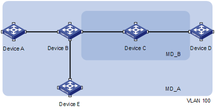
CFD exchanges messages and performs operations on a per-domain basis. By planning MDs properly in a network, you can use CFD to locate failure points rapidly.
Maintenance association
A maintenance association (MA) is a set of maintenance points (MPs) in a MD. An MA is identified by the “MD name + MA name”.
An MA serves a VLAN. Packets sent by the MPs in an MA carry the corresponding VLAN tag. An MP can receive packets sent by other MPs in the same MA.
Maintenance point
An MP is configured on a port and belongs to an MA. MPs fall into two types: maintenance association end points (MEPs) and maintenance association intermediate points (MIPs).
l MEP
Each MEP is identified by an integer called a MEP ID. The MEPs of an MD define the range and boundary of the MD. The MA and MD that a MEP belongs to define the VLAN attribute and level of the packets sent by the MEP. MEPs fall into inward-facing MEPs and outward-facing MEPs.
The level of a MEP determines the levels of packets that the MEP can process. The packets transmitted from a MEP carry the level of the MEP. An MEP forwards packets at a higher level and processes packet of its level or lower. The processing procedure is specific to packets in the same VLAN. Packets of different VLANs are independent.
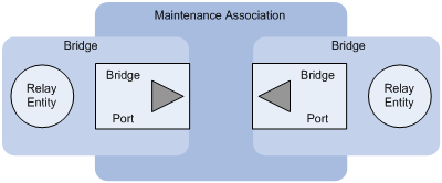
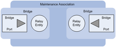
The direction of a MEP determines the position of the MD relative to the port. In Figure 1-2, outward-facing MEPs are configured on the two ports. In Figure 1-3, inward-facing MEPs are configured on the two ports.
An outward-facing MEP communicates through the wire side connected to the port; an inward-facing MEP communicates through the relay function side.
l MIP
A MIP is internal to an MD. It cannot send CFD packets actively; however, it can handle and respond to CFD packets. The MA and MD that a MIP belongs to define the VLAN attribute and level of the packets received.
By cooperating with MEPs, a MIP can perform a function similar to ping and traceroute. Like a MEP, a MIP forwards packets at a higher level without any processing.
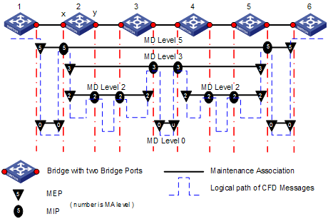
Figure 1-4 demonstrates a grading example of the CFD module. In the figure, there are six devices, labeled 1 through 6 respectively. Suppose each device has two ports, and MEPs and MIPs are configured on some of these ports. Four levels of MDs are designed in this example, the bigger the number, the higher the level and the larger the area covered. In this example, the X port of device 2 is configured with the following MPs: a level 5 MIP, a level 3 inward-facing MEP, a level 2 inward-facing MEP, and a level 0 outward-facing MEP.
Basic Functions of CFD
CFD works effectively only in properly-configured networks. Its functions, which are implemented through the MPs, include:
l Continuity check (CC);
l Loopback (LB)
l Linktrace (LT)
Continuity check
Continuity check is responsible for checking the connectivity between MEPs. Connectivity faults are usually caused by device faults or configuration errors. This function is implemented through periodic sending of continuity check messages (CCMs) by the MEPs. As a multicast message, a CCM sent by one MEP is intended to be received by all the other MEPs in the same MA. If a MEP fails to receive the CCMs within 3.5 sending periods, the link is regarded as faulty and a corresponding log is generated. When multiple MEPs send CCMs at the same time, the multipoint-to-multipoint link check is achieved.
Loopback
Similar to ping at the IP layer, loopback is responsible for verifying the connectivity between a local device and a remote device. To implement this function, the local MEP sends loopback messages (LBMs) to the remote MEP. Depending on whether the local MEP can receive a loopback reply message (LBR) from the remote MEP, the link state between the two can be verified. LBMs and LBRs are unicast messages. They are used to verify the connectivity between two points.
Linktrace
Linktrace is responsible for identifying the path between the source MEP and the destination MEP. This function is implemented in the following way: the source MEP multicasts linktrace messages (LTMs) to the destination MEP. After receiving the messages, the destination MEP and the MIPs that the LTMs pass send back linktrace reply messages (LTRs) to the source MEP. Based on the reply messages, the source MEP can identify the path to the destination MEP. Note that LTMs are multicast frames while LTRs are unicast frames.
Protocols and Standards
The CFD function is implemented in accordance with IEEE P802.1ag.
CFD Configuration Task List
For CFD to work effectively, you should first design the network by performing the following tasks:
l Grade the MDs in the entire network, and define the boundary of each MD.
l Assign a name for each MD. Make sure that the same MD has the same name on different devices.
l Define the MA in each MD according to the VLAN you want to monitor.
l Assign a name for each MA. Make sure that the same MA in the same MD has the same name on different devices.
l At the edges of MD and MA, MPs should be designed at the device port. MEPs can be designed on devices or ports that are not at the edges.
Complete the following tasks to configure CFD:
|
Tasks |
Remarks |
|
Required These configurations are the foundation for other configuration tasks. |
|
|
Required Configuring the MEPs to send CCMs to manage link connectivity |
|
|
Optional |
|
|
Optional Tracing link fault and finding the path between the source MEP and target MEP |
![]()
l Normally, a port blocked by STP cannot receive, send, or respond to CFD messages. however, if the port is configured as an outward-facing MEP, it can still receive and send CCM messages even if it is blocked by STP.
l Only Ethernet ports support CFD.
Basic Configuration Tasks
Basic configuration tasks include:
l Configuring Service Instance
l Configuring MIP Generation Rules
![]()
Configuring Service Instance
A service instance is indicated by an integer to represent an MA in an MD. The MD and MA define the level and VLAN attribute of the messages handled by the MPs in a service instance.
Follow these steps to configure a service instance:
|
Use the command... |
Remarks |
|
|
Enter system view |
system-view |
— |
|
Enable CFD |
cfd enable |
Required CFD is disabled by default. |
|
Create an MD |
cfd md md-name level level-value |
Required Not created by default |
|
Create an MA |
cfd ma ma-name md md-name vlan vlan-id |
Required Not created by default |
|
Create a service instance |
cfd service-instance instance-id md md-name ma ma-name |
Required Not created by default |
![]()
l These configuration tasks are the foundation for other CFD configuration tasks.
l The last three steps in the table above must be performed strictly in order.
Configuring MEP
MEPs are functional entities in a service instance. CFD is implemented through operations on MEPs, which provides such functions as CC, LB, LT and gives prompts on error CCMs and cross connections. As a MEP is configured on a service instance, the MD level and VLAN attribute of the service instance become the attribute of the MEP.
Follow these steps to configure a MEP:
|
To do... |
Use the command... |
Remarks |
|
Enter system view |
system-view |
— |
|
Enter Ethernet interface view |
interface interface-type interface-number |
— |
|
Configure a MEP |
cfd mep mep-id service-instance instance-id { inbound | outbound } |
Required Not configured by default |
|
Configure a remote MEP for a MEP in the same service instance |
cfd remote-mep remote-mep-id service-instance instance-id mep mep-id |
Required No remote MEP is configured for a MEP by default. |
|
Enable the MEP |
cfd mep service-instance instance-id mep mep-id enable |
Required Disabled by default |
Configuring MIP Generation Rules
As functional entities in a service instance, MIPs deal with LBM and LTM messages.
MIPs are generated on each port according to some rules. You can choose appropriate MIP generation rules based on your network design.
Follow these steps to configure the rules for generating MIPs:
|
To do... |
Use the command... |
Remarks |
|
Enter system view |
system-view |
— |
|
Configure the rules for generating MIPs |
cfd mip-rule { explicit | default } service-instance instance-id |
Required By default, neither the MIPs nor the rules for generating MIPs are configured. |
MIPs are generated on each port automatically according to the rules specified in the cfd mip-rule command. If a port has no MIP, the system will check the MAs in each MD (from low to high levels), and follow the rules in Table 1-1 to create or not create MIPs (within a single VLAN):
Table 1-1 Rules for generating MIP
|
MIP exists on low level MA |
The cfd mip-rule command is configured as |
MEP exists on low level MA |
Create MIP or not |
|
Yes |
— |
— |
No |
|
No |
Explicit |
No |
No |
|
Yes |
Yes |
||
|
Default |
— |
Yes |
Each of the following actions or cases can cause MIPs to be created or deleted after you have configured the cfd mip-rule command:
l Enabling CFD (use the cfd enable command)
l Creating or deleting the MEPs on a port
l Changes occur to the VLAN attribute of a port
l The rule specified in the cfd mip-rule command changes
Configuring CC on MEPs
After the CC function is configured, MEPs can send CCMs mutually to check the connectivity between them.
Configuration Prerequisites
Before configuring this function, you should first complete the MEP configuration.
Configuring Procedure
Follow these steps to configure CC on a MEP:
|
To do... |
Use the command... |
Remarks |
|
Enter system view |
system-view |
— |
|
Configure the interval field value in the CCM messages sent by MEPs |
cfd cc interval interval-field-value service-instance instance-id |
Optional By default, the interval filed value is 5. |
|
Enter Ethernet interface view |
interface interface-type interface-number |
— |
|
Enable CCM sending on a MEP |
cfd cc service-instance instance-id mep mep-id enable |
Required Disabled by default |
The relationship between the interval field value in the CCM messages, the interval between CCM messages and the timeout time of the remote MEP is illustrated in Table 1-2.
|
The interval field value |
The interval between CCM messages |
The timeout time of the remote MEP |
|
5 |
1 second |
3.5 seconds |
|
6 |
10 seconds |
35 seconds |
|
7 |
60 seconds |
210 seconds |
![]()
On different devices, the MEPs belonging to the same MD and MA should be configured with the same time interval for CCMs sending.
Configuring LB on MEPs
The LB function can verify the link state between two ends after CC detects a link fault.
Configuration Prerequisites
Before configuring this function, you should first complete the MEP and MIP configuration tasks.
Configuration Procedure
Follow these steps to configure LB on MEP:
|
To do... |
Use the command... |
Remarks |
|
Enter system view |
system-view |
— |
|
Enable LB |
cfd loopback service-instance instance-id mep mep-id { target-mep target-mep-id | target-mac mac-address } [ number loopback-number ] |
Required Disabled by default |
Configuring LT on MEPs
LT can trace the path between the specified MEP and the target MEP, and can also locate link faults by sending LT messages automatically. The two functions are implemented in the following way:
l To implement the first function, the specified MEP first sends LTM messages to the target MEP. Based on the LTR messages in response to the LTM messages, the path between the two MEPs can be identified.
l In the latter case, after LT messages automatic sending is enabled, if a MEP fails to receive the CCMs from the remote MEP within 3.5 sending intervals, the link between the two is regarded as faulty and LTMs will be sent out. Based on the LTRs that echo back, the fault source can be located.
Configuration Prerequisites
Before configuring this function, you should first complete MEP and MIP configuration tasks.
Finding the Path Between a Source MEP and a Target MEP
Follow these steps to find the path between a source MEP and a target MEP:
|
To do... |
Use the command... |
Remarks |
|
Enter system view |
system-view |
— |
|
Find the path between a source MEP and a target MEP |
cfd linktrace service-instance instance-id mep mep-id { target-mep target-mep-id | target-mac mac-address } [ ttl ttl-value ] [ hw-only ] |
Required |
Enabling Automatic LT Messages Sending
Follow these steps to enable automatic LT messages sending:
|
To do... |
Use the command... |
Remarks |
|
Enter system view |
system-view |
— |
|
Enable automatic LT messages sending |
cfd linktrace auto-detection [ size size-value ] |
Required Disabled by default |
Displaying and Maintaining CFD
|
To do... |
Use the command... |
Remarks |
|
Display CFD status |
display cfd status |
Available in any view |
|
Display MD configuration information |
display cfd md |
Available in any view |
|
Display MA configuration information |
display cfd ma [ [ ma-name ] md md-name ] |
Available in any view |
|
Display service instance configuration information |
display cfd service-instance [ instance-id ] |
Available in any view |
|
Display MP information |
display cfd mp [ interface interface-type interface-number ] |
Available in any view |
|
Display the attribute and running information of the MEPs |
display cfd mep mep-id service-instance instance-id |
Available in any view |
|
Display LTR information received by a MEP |
display cfd linktrace-reply [ service-instance instance-id [ mep mep-id ] ] |
Available in any view |
|
Display the information of a remote MEP |
display cfd remote-mep service-instance instance-id mep mep-id |
Available in any view |
|
Display the content of the LTR that responds to LTM messages |
display cfd linktrace-reply auto-detection [ size size-value ] |
Available in any view |
CFD Configuration Examples
This section covers the following topics:
l Configuring Service Instance
l Configuring MEP and Enabling CC on it
l Configuring the Rules for Generating MIPs
Configuring Service Instance
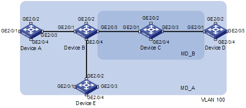
Network requirements
As shown in Figure 1-5, there are five devices in the MDs. Each device has four ports belonging to VLAN 100. The light blue square frame and the blue one specify two different MDs.
l Two MDs, MD_A (indicated by the light blue square frame, with level 5) and MD_B (indicated by the blue square frame, with level 3)) are designed in this network.
l Define the edge ports of each MD, and define the MD of each port.
l The VLAN IDs of each MA in the two MDs are all 100.
Configuration considerations
According to the network diagram, you should perform the following configurations:
l Configure MD_A on Device A and Device E
l Configure MD_B on Device C
l Configure MD_A and MD_B on Device B and Device D
l Configure an MA in each MD
l Configure a service instance for each MA
Configuration procedure
1) Configuration on Device A (configuration on Device E is the same as that on Device A)
<DeviceA> system-view
[DeviceA] cfd enable
[DeviceA] cfd md MD_A level 5
[DeviceA] cfd ma MA_MD_A md MD_A vlan 100
[DeviceA] cfd service-instance 1 md MD_A ma MA_MD_A
2) Configuration on Device C
<DeviceC> system-view
[DeviceC] cfd enable
[DeviceC] cfd md MD_B level 3
[DeviceC] cfd ma MA_MD_B md MD_B vlan 100
[DeviceC] cfd service-instance 2 md MD_B ma MA_MD_B
3) Configuration on Device B (configuration on Device D is the same as that on Device B)
<DeviceB> system-view
[DeviceB] cfd enable
[DeviceB] cfd md MD_A level 5
[DeviceB] cfd ma MA_MD_A md MD_A vlan 100
[DeviceB] cfd service-instance 1 md MD_A ma MA_MD_A
[DeviceB] cfd md MD_B level 3
[DeviceB] cfd ma MA_MD_B md MD_B vlan 100
[DeviceB] cfd service-instance 2 md MD_B ma MA_MD_B
After the above configuration, you can use the commands display cfd md, display cfd ma and display cfd service-instance to verify your configuration.
Configuring MEP and Enabling CC on it
Network requirements
After finishing service instance configuration, you can start to design the MEPs.
l MEPs are configured at the edge or border of MDs. Find the edge port of each MD.
l Decide the MEP direction (inward-facing or outward-facing) on each edge port based on the MD position.
l Assign a unique ID to each MEP in an MA.
l Decide the remote MEP for each MEP, and enable these MEPs.
Figure 1-6 Diagram of MD and MEP
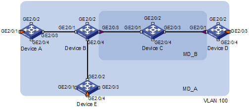
Configuration considerations
l In MD_A, there are three edge ports: GigabitEthernet 2/0/1 on Device A, GigabitEthernet 2/0/3 on Device D and GigabitEthernet 2/0/4 on Device E. Configure inward-facing MEPs on these ports respectively.
l In MD_B, there are two edge ports: GigabitEthernet 2/0/3 on Device B and GigabitEthernet 2/0/1 on Device D. Configure outward-facing MEPs on the two ports respectively.
l In MD_A and MD_B, each MEP checks the messages from other MEPs.
Configuration procedure
1) On Device A
<DeviceA> system-view
[DeviceA] interface GigabitEthernet 2/0/1
[DeviceA-GigabitEthernet2/0/1] cfd mep 1001 service-instance 1 inbound
[DeviceA-GigabitEthernet2/0/1] cfd remote-mep 5001 service-instance 1 mep 1001
[DeviceA-GigabitEthernet2/0/1] cfd remote-mep 4002 service-instance 1 mep 1001
[DeviceA-GigabitEthernet2/0/1] cfd mep service-instance 1 mep 1001 enable
[DeviceA-GigabitEthernet2/0/1] cfd cc service-instance 1 mep 1001 enable
2) On Device B
<DeviceB> system-view
[DeviceB] interface GigabitEthernet 2/0/3
[DeviceB-GigabitEthernet2/0/3] cfd mep 2001 service-instance 2 outbound
[DeviceB-GigabitEthernet2/0/3] cfd remote-mep 4001 service-instance 2 mep 2001
[DeviceB-GigabitEthernet2/0/3] cfd mep service-instance 2 mep 2001 enable
[DeviceB-GigabitEthernet2/0/3] cfd cc service-instance 2 mep 2001 enable
3) On Device D
<DeviceD> system-view
[DeviceD] interface GigabitEthernet 2/0/1
[DeviceD-GigabitEthernet2/0/1] cfd mep 4001 service-instance 2 outbound
[DeviceD-GigabitEthernet2/0/1] cfd remote-mep 2001 service-instance 2 mep 4001
[DeviceD-GigabitEthernet2/0/1] cfd mep service-instance 2 mep 4001 enable
[DeviceD-GigabitEthernet2/0/1] cfd cc service-instance 2 mep 4001 enable
[DeviceD-GigabitEthernet2/0/1] interface GigabitEthernet 2/0/3
[DeviceD-GigabitEthernet2/0/3] cfd mep 4002 service-instance 1 inbound
[DeviceD-GigabitEthernet2/0/3] cfd remote-mep 1001 service-instance 1 mep 4002
[DeviceD-GigabitEthernet2/0/3] cfd remote-mep 5001 service-instance 1 mep 4002
[DeviceD-GigabitEthernet2/0/3] cfd mep service-instance 1 mep 4002 enable
[DeviceD-GigabitEthernet2/0/3] cfd cc service-instance 1 mep 4002 enable
4) On Device E
<DeviceE> system-view
[DeviceE] interface GigabitEthernet 2/0/4
[DeviceE-GigabitEthernet2/0/4] cfd mep 5001 service-instance 1 inbound
[DeviceE-GigabitEthernet2/0/4] cfd remote-mep 1001 service-instance 1 mep 5001
[DeviceE-GigabitEthernet2/0/4] cfd remote-mep 4002 service-instance 1 mep 5001
[DeviceE-GigabitEthernet2/0/4] cfd mep service-instance 1 mep 5001 enable
[DeviceE-GigabitEthernet2/0/4] cfd cc service-instance 1 mep 5001 enable
After the above configuration, you can use the commands display cfd mp and display cfd mep to verify your configuration.
Configuring the Rules for Generating MIPs
Network requirements
After finishing MEP configuration, you can continue to configure the MIPs.
MIPs, which are generated by some rules, are configured in the following way:
l Decide the device on which MIPs are to be configured.
l Choose suitable rules for MIP generation. By default, MIP is not configured on a device. If MIPs are to be configured on each port in the MD, you should choose the default rule. If MIPs are to be configured only when the low level MDs having MEP, you should choose the explicit rule.
Figure 1-7 Diagram of MD and MP
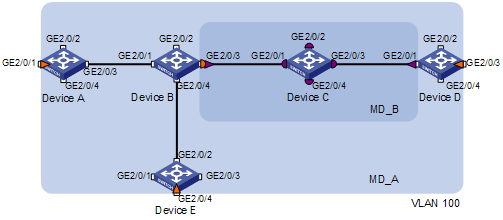
Configuration considerations
l In MD_A, Device B is designed to have MIPs when its port is configured with low level MEPs. In this case, port GigabitEthernet 2/0/3 is configured with MEPs of MD_B, and the MIPs of MD_A can be configured on this port. Based on the design, you should configure the MIP generation rule of MD_A to explicit on Device B.
l The MIPs of MD_B are designed on Device C, and are configured on all ports. Based on this design, the MIP generation rule should be configured as default.
Configuration procedure
1) Configure Device B
<DeviceB> system-view
[DeviceB] cfd mip-rule explicit service-instance 1
2) Configure Device C
<DeviceC> system-view
[DeviceC] cfd mip-rule default service-instance 2
After the above operation, you can use the display cfd mp command to verify your configuration.
Configuring LB on MEPs
Network requirements
Use the LB function to trace the fault source after CC detects a link fault.
Configuration considerations
As shown in Figure 1-6, enable LB on Device A so that Device A can send LBM messages to MEPs on Device D.
Configuration procedure
# Configure Device A
<DeviceA> system-view
[DeviceA] cfd loopback service-instance 1 mep 1001 target-mep 4002
Configuring LT on MEPs
Network requirements
Use the LT function to find the path and locate the fault after you obtain the state of the entire network through the CC.
Configuration considerations
As shown in Figure 1-6, enable LT on Device A so that Device A can send LTM messages to the MEP on Device D.
Configuration procedure
# Configure Device A
<DeviceA> system-view
[DeviceA] cfd linktrace service-instance 1 mep 1001 target-mep 4002
