- Table of Contents
-
- 01-Access Volume
- 00-Access Volume Organization
- 01-Ethernet Interface Configuration
- 02-Link Aggregation Configuration
- 03-Port Isolation Configuration
- 04-Service Loopback Group Configuration
- 05-DLDP Configuration
- 06-Smart Link Configuration
- 07-LLDP Configuration
- 08-VLAN Configuration
- 09-GVRP Configuration
- 10-QinQ Configuration
- 11-BPDU Tunneling Configuration
- 12-VLAN Mapping Configuration
- 13-Ethernet OAM Configuration
- 14-Connectivity Fault Detection Configuration
- 15-EPON-OLT Configuration
- 16-MSTP Configuration
- 17-RRPP Configuration
- 18-Mirroring Configuration
- Related Documents
-
| Title | Size | Download |
|---|---|---|
| 13-Ethernet OAM Configuration | 147.71 KB |
Table of Contents
Ethernet OAM Configuration Task List
Configuring Basic Ethernet OAM Functions
Configuring Errored Frame Event Detection
Configuring Errored Frame Period Event Detection
Configuring Errored Frame Seconds Event Detection
Displaying and Maintaining Ethernet OAM Configuration
Ethernet OAM Configuration Example
Configuring Extended OAM Manageability
When configuring the Ethernet OAM function, go to these sections for information you are interested in:
l Ethernet OAM Configuration Task List
l Configuring Basic Ethernet OAM Functions
l Enabling OAM Loopback Testing
l Displaying and Maintaining Ethernet OAM Configuration
l Ethernet OAM Configuration Example
Ethernet OAM Overview
Ethernet OAM (operation, administration, and maintenance) is a tool monitoring Layer-2 link status by sending OAM protocol data units (OAMPDUs) between devices. It helps network administrators manage their networks effectively.
Currently, Ethernet OAM is mainly used to address common link-related issues on the “last mile.” By enabling Ethernet OAM on two devices connected by a point-to-point connection, you can monitor the status of the link. Ethernet OAM provides the following functions:
l Link performance monitoring, for detecting link errors
l Fault detection and alarm, for reporting link errors to the administrators
l Loopback testing, for detecting link errors through non-OAMPDUs
![]()
Throughout this document, a port with Ethernet OAM enabled is called an Ethernet OAM entity or an OAM entity.
Types of Ethernet OAMPDUs
Figure 1-1 shows the formats of different types of OAMPDU.
Figure 1-1 The formats of different types of Ethernet OAMPDU
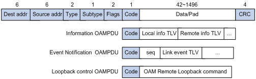
The fields in an OAMPDU are described as follows:
Table 1-1 Description of the fields in an OAMPDU
|
Field |
Description |
|
Dest addr |
Destination MAC address of the Ethernet OAMPDU. It is a slow protocol multicast address 0180c2000002. As slow protocol packet cannot be forwarded by bridges, Ethernet OAMPDUs cannot be forwarded. |
|
Source addr |
Source MAC address of the Ethernet OAMPDU. It is the bridge MAC address of the sending side and is a unicast MAC address. |
|
Type |
Type of the encapsulated protocol in the Ethernet OAMPDU. The value is 0x8809. |
|
Subtype |
The specific protocol being encapsulated in the Ethernet OAMPDU. The value is 0x03. |
|
Flags |
Status information of an Ethernet OAM entity. |
|
Code |
Type of the Ethernet OAMPDU |
Table 1-2 shows the function of the three types of OAMPDUs.
Table 1-2 Functions of different types of OAMPDUs
|
OAMPDU type |
Function |
|
Information OAMPDU |
Used for transmitting state information of an Ethernet OAM entity (including the information about the local device and remote devices, and customized information) to the remote Ethernet OAM entity and maintaining OAM connections |
|
Event Notification OAMPDU |
Used by link monitoring to notify the remote OAM entity when it detects problems on the link in between. |
|
Loopback Control OAMPDU |
Used for remote loopback control. By inserting the information used to enable/disable loopback to a loopback control OAMPDU, you can enable/disable loopback on a remote OAM entity. |
Ethernet OAM Implementation
This section describes the working procedures of Ethernet OAM.
Ethernet OAM connection establishment
Ethernet OAM connection is the base of all the other Ethernet OAM functions. OAM connection establishment is also known as the Discovery phase, where an Ethernet OAM entity discovers remote OAM entities and establishes sessions with them.
In this phase, interconnected OAM entities notify the peer of their OAM configuration information and the OAM capabilities of the local nodes by exchanging Information OAMPDUs and determine whether Ethernet OAM connections can be established. An Ethernet OAM connection can be established only when the settings concerning Loopback, link detecting, and link event of the both sides match. After an Ethernet OAM connection is established, Ethernet OAM takes effect on it.
As for Ethernet OAM connection establishment, a device can operate in active Ethernet OAM mode or passive Ethernet OAM mode. Table 1-3 compares active Ethernet OAM mode with passive Ethernet OAM mode.
Table 1-3 Active Ethernet OAM mode and passive Ethernet OAM mode
|
Item |
Active Ethernet OAM mode |
Passive Ethernet OAM mode |
|
Initiating OAM Discovery |
Available |
Unavailable |
|
Responding to OAM Discovery |
Available |
Available |
|
Transmitting Information OAMPDUs |
Available |
Available |
|
Transmitting Event Notification OAMPDUs |
Available |
Available |
|
Transmitting Information OAMPDUs with the Data/Pad field being empty |
Available |
Available |
|
Transmitting Loopback Control OAMPDUs |
Available |
Unavailable |
|
Responding to Loopback Control OAMPDUs |
Available (if both sides operate in active OAM mode) |
Available |
|
Transmitting organization-specific OAMPDUs |
Available |
Available |
![]()
l OAM connections can be initiated only by OAM entities operating in active OAM mode, while those operating in passive mode wait and respond to the connection requests sent by their peers.
l No OAM connection can be established between OAM entities operating in passive OAM mode.
After an Ethernet OAM connection is established, the Ethernet OAM entities on both sides exchange Information OAMPDUs periodically to keep the Ethernet OAM connection valid. If an Ethernet OAM entity receives no Information OAMPDU for five seconds, the Ethernet OAM connection is disconnected.
![]()
The interval to send Information OAMPDUs is determined by a timer. Up to ten Information OAMPDUs can be sent in a second.
Link Monitoring
Error detection in an Ethernet is difficult, especially when the physical connection in the network is not disconnected but network performance is degrading gradually. Link monitoring is used to detect and indicate link faults in various environments. Ethernet OAM implements link monitoring through the exchange of Event Notification OAMPDUs. Upon detecting a link error event listed in Table 1-4, the local OAM entity sends an Event Notification OAMPDU to notify the remote OAM entity. With the log information, network administrators can keep track of network status in time. .Table 1-4 describes the link events.
Table 1-4 Ethernet OAM link error events
|
Ethernet OAM link events |
Description |
|
Errored symbol event |
An errored symbol event occurs when the number of detected symbol errors over a specific detection interval exceeds the predefined threshold. |
|
Errored frame event |
An errored frame event occurs when the number of detected error frames over a specific interval exceeds the predefined threshold. |
|
Errored frame period event |
An errored frame period event occurs if the number of frame errors in specific number of received frames exceeds the predefined threshold |
|
Errored frame seconds event |
When the number of error frame seconds detected on a port over a detection interval reaches the error threshold, an errored frame seconds event occurs. |
![]()
l The system transforms the period of detecting errored frame period events into the maximum number of 64-byte frames that a port can send in the specific period, that is, the system takes the maximum number of frames sent as the period. The maximum number of frames sent is calculated using this formula: the maximum number of frames = interface bandwidth (bps) × errored frame period event detection period (in ms)/(64 × 8 × 1000)
l If errored frames appear in a certain second, this second is called an errored frame second.
Remote Fault Detection
In a network where traffic is interrupted due to device failures or unavailability, the flag field defined in Ethernet OAMPDUs allows an Ethernet OAM entity to send error information to its peer. It can identify the critical link error events listed in Table 1-5.
Table 1-5 Critical link error events
|
Ethernet OAM link events |
Description |
|
Link Fault |
Peer link signal is lost. |
|
Dying Gasp |
An unexpected fault, such as power failure, occurred. |
|
Critical event |
An undetermined critical event happened. |
As Information OAMPDUs are exchanged periodically across established OAM connections, an Ethernet OAM entity can inform one of its OAM peers of link faults through Information OAMPDUs. Therefore, the network administrator can keep track of link status in time through the log information and troubleshoot in time.
Remote loopback testing
Remote loopback testing is available only after the Ethernet OAM connection is established. With remote loopback enabled, the Ethernet OAM entity operating in active Ethernet OAM mode issues remote loopback requests and the peer responds to them. If the peer operates in the loopback mode, it returns all the PDUs except Ethernet OAMPDUs to the senders along the original paths.
Performing remote loopback testing periodically helps to detect network faults in time. Furthermore, performing remote loopback testing by network segments helps to locate network faults.
Standards and Protocols
Ethernet OAM is defined in IEEE 802.3h.
Ethernet OAM Configuration Task List
Complete the following tasks to configure Ethernet OAM:
|
Task |
Remarks |
|
|
Required |
||
|
Optional |
||
|
Optional |
||
|
Optional |
||
|
Optional |
||
Configuring Basic Ethernet OAM Functions
As for Ethernet OAM connection establishment, a device can operate in active mode or passive mode. After Ethernet OAM is enabled on an Ethernet port, according to its Ethernet OAM mode, the Ethernet port establishes an Ethernet OAM connection with its peer port.
Follow these steps to configure basic Ethernet OAM functions:
|
To do… |
Use the command… |
Remarks |
|
Enter system view |
System-view |
— |
|
Enter Ethernet port view |
interface interface-type interface-number |
— |
|
Set Ethernet OAM operating mode |
oam mode { active | passive } |
Optional The default is active Ethernet OAM mode. |
|
Enable Ethernet OAM on the current port |
oam enable |
Required Ethernet OAM is disabled by default. |
![]()
To change the Ethernet OAM operating mode on an Ethernet OAM-enabled port, you need to first disable Ethernet OAM on the port.
Configuring Link Monitoring
![]()
After Ethernet OAM connections are established, the link monitoring periods and thresholds configured in this section take effect on all Ethernet ports automatically.
holds configured in this section take effect on all Ethernet ports automatically.
Configuring Errored Frame Event Detection
An errored frame event occurs when the number of detected error frames over a specific interval exceeds the predefined threshold.
Follow these steps to configure errored frame event detection:
|
To do… |
Use the command… |
Remarks |
|
Enter system view |
system-view |
— |
|
Configure the errored frame event detection interval |
oam errored-frame period period-value |
Optional 1 second by default |
|
Configure the errored frame event triggering threshold |
oam errored-frame threshold threshold-value |
Optional 1 by default |
Configuring Errored Frame Period Event Detection
An errored frame period event occurs if the number of frame errors in specific number of received frames exceeds the predefined threshold.
Follow these steps to configure errored frame period event detection:
|
To do… |
Use the command… |
Remarks |
|
Enter system view |
system-view |
— |
|
Configure the errored frame period event detection period |
oam errored-frame-period period period-value |
Optional 1000 milliseconds by default |
|
Configure the errored frame period event triggering threshold |
oam errored-frame-period threshold threshold-value |
Optional 1 by default |
Configuring Errored Frame Seconds Event Detection
An errored frame seconds event occurs when the number of error frame seconds detected on a port over a detection interval exceeds the error threshold.
Follow these steps to configure errored frame seconds event detection:
|
To do… |
Use the command… |
Remarks |
|
Enter system view |
system-view |
— |
|
Configure the errored frame seconds event detection interval |
oam errored-frame-seconds period period-value |
Optional 60 second by default |
|
Configure the errored frame seconds event triggering threshold |
oam errored-frame-seconds threshold threshold-value |
Optional 1 by default |
![]()
Make sure the errored frame seconds triggering threshold is less than the errored frame seconds detection interval. Otherwise, no errored frame seconds event can be generated.
Enabling OAM Loopback Testing
Follow these steps to enable Ethernet OAM loopback testing:
|
To do… |
Use the command… |
Remarks |
|
Enter system view |
System-view |
— |
|
Enter Ethernet port view |
interface interface-type interface-number |
— |
|
Enable Ethernet OAM loopback testing |
oam loopback |
Required Disabled by default. |
![]()
l Ethernet OAM loopback testing is available only after the Ethernet OAM connection is established and can be performed only by the Ethernet OAM entities operating in active Ethernet OAM mode.
l Loopback testing is available only on full-duplex links that support remote loopback at both ends.
l Ethernet OAM loopback testing needs the support of the peer hardware.
l Enabling Ethernet OAM loopback testing interrupts data communications. After Ethernet OAM loopback testing is disabled, all the ports involved will shut down and then come up. Ethernet OAM loopback testing is disabled when you execute the undo oam enable command to disable Ethernet OAM, when you execute the undo oam loopback command to disable Ethernet OAM loopback testing, or when the Ethernet OAM connection times out.
l Ethernet OAM loopback testing is only applicable to individual links. It is not applicable to link aggregation member ports or service loopback group member ports. In addition, you cannot assign ports where Ethernet OAM loopback testing is being performed to link aggregation groups or service loopback groups. For more information about link aggregation groups and service loopback groups, refer to Link Aggregation Configuration and Service Loopback Group Configuration in the Access Volume.
l Enabling internal loopback test on a port in remote loopback test can terminate the remote loopback test. For more information about loopback test, refer to Ethernet Interface Configuration in the Access Volume.
Displaying and Maintaining Ethernet OAM Configuration
|
To do… |
Use the command… |
Remarks |
|
Display global Ethernet OAM configuration |
display oam configuration |
Available in any view |
|
Display the statistics on critical events after an Ethernet OAM connection is established |
display oam critical-event [ interface interface-type interface-number ] |
|
|
Display the statistics on Ethernet OAM link error events after an Ethernet OAM connection is established or after you clear the statistics |
display oam link-event { local | remote } [ interface interface-type interface-number ] |
|
|
Display the information about an Ethernet OAM connection |
display oam { local | remote } [ interface interface-type interface-number ] |
|
|
Clear statistics on Ethernet OAM packets and Ethernet OAM link error events |
reset oam [ interface interface-type interface-number ] |
Available in user view only |
Ethernet OAM Configuration Example
Network requirements
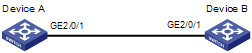
l Enable Ethernet OAM on Device A and Device B to manage links on data link layer.
l Monitor link performance and collect statistics about the error frames received by Device A.
Network diagram
Figure 1-2 Network diagram for Ethernet OAM configuration
Configuration procedure
1) Configure Device A:
# Configure GigabitEthernet 2/0/1 to operate in passive Ethernet OAM mode and enable Ethernet OAM for it.
<DeviceA> system-view
[DeviceA] interface gigabitethernet 2/0/1
[DeviceA-GigabitEthernet2/0/1] oam mode passive
[DeviceA-GigabitEthernet2/0/1] oam enable
[DeviceA-GigabitEthernet2/0/1] quit
# Set the errored frame detection interval to 20 seconds and set the errored frame event triggering threshold to 10.
[DeviceA] oam errored-frame period 20
[DeviceA] oam errored-frame threshold 10
2) Configure Device B
# Configure GigabitEthernet2/0/1 to operate in active Ethernet OAM mode (the default) and enable Ethernet OAM for it.
<DeviceB> system-view
[DeviceB] interface gigabitEthernet2/0/1
[DeviceA-GigabitEthernet2/0/1] oam mode active
[DeviceB-GigabitEthernet2/0/1] oam enable
[DeviceB-GigabitEthernet2/0/1] quit
3) Verify the configuration
Use the display oam configuration command to display the Ethernet OAM configuration. For example:
# Display the Ethernet OAM configuration on Device A.
[DeviceA] display oam configuration
Configuration of the link event window/threshold :
--------------------------------------------------------------------------
Errored-symbol Event period(in seconds) : 1
Errored-symbol Event threshold : 1
Errored-frame Event period(in seconds) : 20
Errored-frame Event threshold : 10
Errored-frame-period Event period(in ms) : 1000
Errored-frame-period Event threshold : 1
Errored-frame-seconds Event period(in seconds) : 60
Errored-frame-seconds Event threshold : 1
Use the display oam link-event command to display the statistics about Ethernet OAM link events. For example:
# Display Ethernet OAM link event statistics of the remote end of Device B.
[DeviceB] display oam link-event remote
Port :GigabitEthernet2/0/1
Link Status :Up
OAMRemoteErrFrameEvent : (ms = milliseconds)
---------------------------------------------------------------------
Event Time Stamp : 5789 Errored FrameWindow : 10(100ms)
Errored Frame Threshold : 1 Errored Frame : 3
Error Running Total : 35 Event Running Total : 17
The above information indicates that 35 errors occurred since Ethernet OAM is enabled on Device A, 17 of which are caused by error frames. The link is instable.
2 Extended OAM Configuration
When configuring extended OAM, go to these sections for information you are interested in:
l Overview
Overview
With an Ethernet passive optical network (EPON) board, an S7500E switch can operate as the optical line terminal (OLT) device of an EPON system and connects to remote optical network unit (ONU) devices.
Extended OAM is mainly used to establish connections between an OLT and its ONU and enable the OLT to manage the ONUs remotely.
Extended OAMPDU
New types of OAMPDUs are introduced in extended OAM. By sending these new types of OAMPDUs, an OLT and its ONUs can send connection requests and responses, and exchange various management information.
Extended information OAMPDU
Extended OAM adds an Organization Specific Information TLV to the information OAMPDU. For details about information OAMPDUs, refer to Types of Ethernet OAMPDUs. An information OAMPDU containing this TLV is called an extended information OAMPDU.
The Organization Specific Information TLV contains the following contents:
l Local Organizationally Unique Identifier (OUI): Identifies the vendor of the local device.
l Supported OUI addresses: Specifies the vendors whose devices can interoperate with the local OLT or ONU device.
l OAM version number: Indicates the version of the OAM protocol used by the local OLT or ONU device.
Organization Specific OAMPDU
Organization Specific OAMPDU is a newly added OAMPDU type. It is identified by the 0xFE field, as shown in Figure 2-1.
Figure 2-1 Organization Specific OAMPDU format
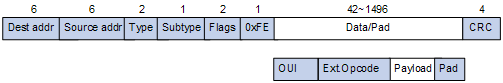
When you remotely manage ONUs on an OLT device, extended OAM can encapsulate various operation and acknowledgement information in the Data field. The data field consists of the following sub-fields:
l OUI: The OUI address of the transmitting device.
l Ext.Opcode: Extended operation code. Extended OAM uses different codes for identifying the operation types of OAMPDUs, as described in Table 2-1.
Table 2-1 Description on the extended operation codes
|
Code |
Operation type |
Description |
|
0x01 |
Extended Variable Request |
Sent from an OLT to an ONU, carrying the user's query instructions. |
|
0x02 |
Extended Variable Response |
Sent from the ONU to the OLT in response to a query request, carrying the requested information. |
|
0x03 |
Set Request |
Sent from the OLT to the ONU, carrying the user's configuration instructions for the ONU. |
|
0x04 |
Set Response |
Sent from the ONU to the OLT after the ONU finishes the configuration instructed by the user. |
|
0x0A |
DBA (Dynamic Bandwidth Allocation) |
Used for performing DBA configuration and query. |
l Payload: Carries the function codes and configuration contents corresponding to the user’s query or configuration instructions. An OLT can configure the functions shown in Extended OAM management for ONUs.
How Extended OAM Works
Extended OAM has two functions: extended OAM discovery and extended OAM management.
Extended OAM discovery
First, the OLT and the ONU use standard OAM to judge whether the link in between is normal. If the link is normal, the OLT and the ONU exchanges Extended Information OAMPDUs to inform each other of their OUI addresses, supported OUI addresses, and OAM version numbers. If the OUI address and OAM version of each end can be supported by the other end, the extended OAM discovery process finishes and data transmission starts. Otherwise, the two ends cannot communicate normally.
Extended OAM management
After finishing extended OAM discovery, the OLT device can remotely configure the ONU by sending Organization Specific OAMPDUs.
The OLT can configure the following functions for the ONU:
l Basic port configurations, including duplex mode, rate, and traffic control.
l VLAN management and configuration
l Multicast
l QoS
l DBA
The OLT can query and configure the functions mentioned above. You can use the related query commands to query the status of a function on the ONU. You can also configure parameters for a function on the OLT, and the OLT will issue the configured parameters to the ONU automatically. The query or configuration command is identified by the Ext.Opcode field in the Organization Specific OAMPDUs. The codes and configurations to be queried or configured are encapsulated in the payload field. For details, refer to Organization Specific OAMPDU.
Configuring Extended OAM
Enabling Extended OAM
On an S7500E switch, you need not enable extend OAM manually; instead, extended OAM is enabled on a port automatically when you enable Ethernet OAM on the port.
Configuring Extended OAM Manageability
For how to configure extended OAM manageability, refer to EPON-OLT Configuration.
